

Organic semiconductors are a new class of materials representing an innovative field of scientific research. Efficient illuminants, such as organic light emitting diodes (OLEDs), will soon help reduce the world's energy consumption for lightning. Today OLEDs can already be found in ultra-thin and super-bright displays of modern mobile high-tech applications. This contribution provides an experimental and conceptual approach for the curricular integration of luminescent semiconducting polymers into science classes.
Los semiconductores orgánicos son una nueva clase de materiales que representan un campo novedoso de investigación científica. Proveen de luz eficientemente, tales como los diodos emisores de luz orgánicos (OLED, por sus siglas en inglés) pronto serán útiles para reducir el consumo mundial de luz. Hoy los OLEDs pueden encontrarse en las carátulas de dispositivos modernos ultra-delgados y súper-brillantes con aplicaciones de alta tecnología móvil. Esta contribución da un enfoque experimental y conceptual para integrar en el currículo escolar los polímeros luminiscentes semiconductores.
An aim of chemical education should be the integration of current topics of industrial and scientific research into school and university curricula. An example for this is the innovative field of organic electronics, in particular the semiconducting polymers for use in optoelectronic devices, such as organic light emitting diodes (OLEDs) and organic photovoltaic cells (OPVs). Optoelectronic devices based on polymers instead of inorganic semiconductors, such as gallium arsenide (GaAs) or cadmium telluride (CdTe), reveal several advantages, respectively lower production costs and newly accessible applications. There are some contributions in German and English didactical literature which deal with related topics, such as conductive polymers or plastic solar cells (Liu and Wang, 2003; Gómez and Segura, 2007; Goto et al., 2008; Müller et al., 2004; Vázquez et al., 2008; Maldonado et al., 2008; Banerji and Tausch, 2010a; 2010b; 2012). Notably Müller et al. (2004) and Maldonado et al. (2008) presented low-cost OLEDs before. Our aim is to offer further experiments on OLEDs and provide didactical materials for the curricular integration of semiconducting polymers and making them internationally accessible. Parts of the following contribution have been published in German journals for chemical education (Banerji and Tausch, 2010a; 2010b; 2012).
2RationaleIn OLEDs molecules are electrically transferred into the excited state, followed by radiative decay of electron-hole-pairs into the ground state. Wavelength and thus color of the emitted light is determined by the energy gap Eg between the HOMO (highest occupied molecule orbital) and LUMO (lowest unoccupied molecule orbital) of the respective molecule. For detailed information on the photochemical basics of luminescence we refer to O’Hara et al. (2005).
Usually the excited state in organic molecules is reached via a chemical reaction or by photoexcitation. The electrical excitation of organic molecules is uncommon and only possible if the molecule (whereupon we further focus on polymers) exhibits: 1) an intrinsic conductivity both for electrons and defect electrons (holes), and 2) an energy level alignment as found in inorganic semiconductors.
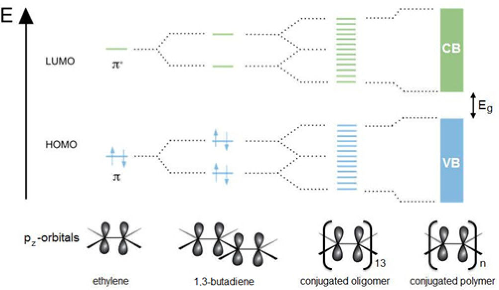
In 2000 A. Heeger, H. Shirakawa and A. McDiarmid received the Nobel Prize for chemistry for their “discovery and development of conductive polymers” (Shirakawa et al., 2001). The clue to electrical conductivity in polymer molecules is a system of conjugated double bonds. It can be explained with the molecule orbital model (Fig. 1).
, 20, 2003.)")
Within a section of sp2-hybridized carbon atoms (hetero-atoms may also be involved) pz-orbitals combine to binding π- and anti binding π*-molecular orbitals (MOs), which are delocalized. The more pz-orbitals combine, the more delocalized MOs are formed. The energy gaps between the π- and the π*- MOs as well as the energy gap Eg decrease with increasing numbers of double bonds. In conjugated polymers the large number of interacting pz-orbitals lead to the formation of a fully occupied π-valence band (VB) and an empty π*-conduction band (CB) and Eg moves into the region of visible light. Electrons can easily be excited from the VB into the CB, which leads to (photo)conductivity. The polymer becomes an organic semiconductor. By chemical doping (oxidation or reduction) electrons are removed from the VB or injected into the CB. This process is coupled to the formation of midgap states. Hereby, the energy gap Eg is closed and electrical conductivity is observed (Rehahn, 2003). For a less sophisticated explanation of conductivity in organic molecules we developed a simple model, which is provided in the supplemental materials (see chap. 4). This model disclaims the formalism and technical terms of the molecule orbital theory and thus is suitable for application in undergraduate classes.
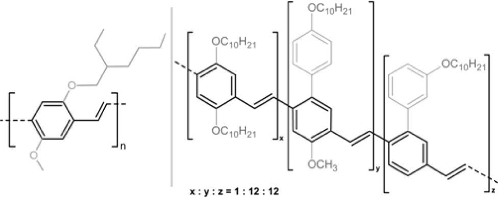
Two examples for well operating OLED polymers are poly[2-methoxy-5-(2-ethylhexyloxy)-1,4-phenylenevinylene] (MEH-PPV) and Superyellow®, an PPV-type polymer from Merck KgaA. Fig. 2 shows the structure of both polymers. The highlighted PPV-backbones are responsible for the optoelectronic properties, while the long-chained alkoxy side groups primarily control solubility for better processing. Both polymers have been used as orange respectively yellow emitter in the low-cost OLED presented in this article (see chap. 3).
 and copolymer Superyellow (right).")
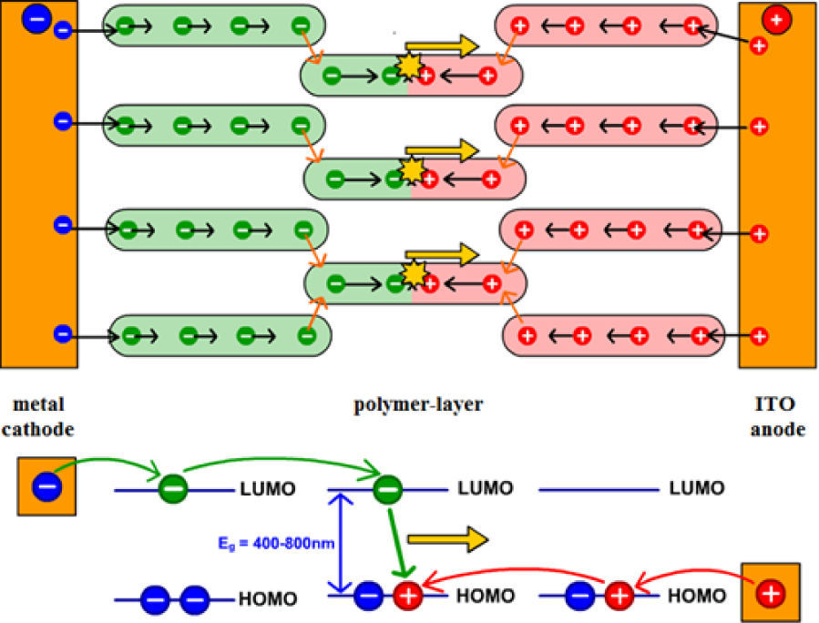
For the emission of light a thin layer of the electroluminescent polymer has to be placed into a diode between a transparent ITO anode (indium tin oxide) and a low work function metal cathode as shown in Fig. 3. When applying a voltage of a few volts, the following elementary processes are initiated.
.")
Principle of electroluminescence in an OLED (Banerji, Tausch & Scherf, 2012).
In a first step electrons are injected into the LUMO1 of molecules close to the cathode and holes are injected into the HOMO1 of molecules close to the anode. For this process it is crucial, that the Fermi levels of the electrodes fit well to the energy levels of the polymer and an intimate contact between all layers is given.
b)Charge transportVia hopping processes (red arrows in Fig. 3) the injected charges drift through the polymer layer from molecule to molecule in opposite directions. These hopping processes are necessary, because there are energetic barriers between the molecules, which the electrons have to overcome for an efficient current flow (Rehahn, 2003).
c)Charge recombination and decay of excitonsWhen electron and hole meet inside a molecule they recombine to give an exciton. For spin-statistical reasons 25% singlet and 75% triplet excitons are generated (Müllen & Scherf, 2006). In fluorescent polymer emitters, as discussed here, singlet excitons primarily decay via fluorescence, while triplet excitons primarily decay via thermal relaxation. This limits the maximum quantum output of fluorescent OLEDs to 25%. The emitted light (yellow arrows in Fig. 3) leaves the device via the transparent anode. The color of the light is determined by the size of the band gap in the molecule, that is mainly controlled by the specific chemical structure of the π-conjugated system (determined by the efficient conjugation length and mainly independent to the length of the macromolecule).
3ExperimentalWe developed four experiments for low-cost self-made OLEDs, which have been tested at approx. 40 schools in Germany, Austria and Switzerland. The costs for one OLED on FTO (fluorine doped tin oxide) glass adds up to approx. $4.50 USD. In this article we want to present the “Standard-OLED” (experiment 1) as well as the Easy-OLED (experiment 2), the two other experiments are add-ons to these basic devices and were described in the supplemental materials (see chap. 4).
Sources of supply- 1.
ITO is expensive, we recommend FTO-glass (TEC 7) available at Sigma-Aldrich, product-nr: 735167.
- 2.
Galinstan® available at Geratherm, Germany. Alternatively use gallium-indium eutectic, available at Sigma-Aldrich, product-nr: 495425.
- 3.
MEH-PPV (Mn=150.000–350.000) is available at Sigma-Aldrich, product-nr: 536512; alternatively use Superyellow® provided by Merck KgaA, Germany.
- 4.
Self adhesive copper-foil is available at ebay.com, search item “copper tape”.
- 5.
Drilling machine or alternatively any rotating tool featuring 3000rpm available at common hardware stores.
Materials: drilling machine (~3000rpm), 0.5 L PET-flask (as splash-protector), multimeter with 2 cables, 2 alligator clips, power supply, 9 V battery, 1mL syringe (one-way), double sided tape, adhesive tape, scissors, Kleenex, 1 ITO-glass (3cm×3cm), MEH-PPV solved in chloroform, (c=3.5g/L), (F, highly flammable) or Superyellow solved in toluene, (c=5g/L), (F, highly flammable), (Xn, noxious), Galinstan or gallium-indium eutectic, adhesive copper-foil, acetone (F, highly flammable), (Xi, irritating).
- i)
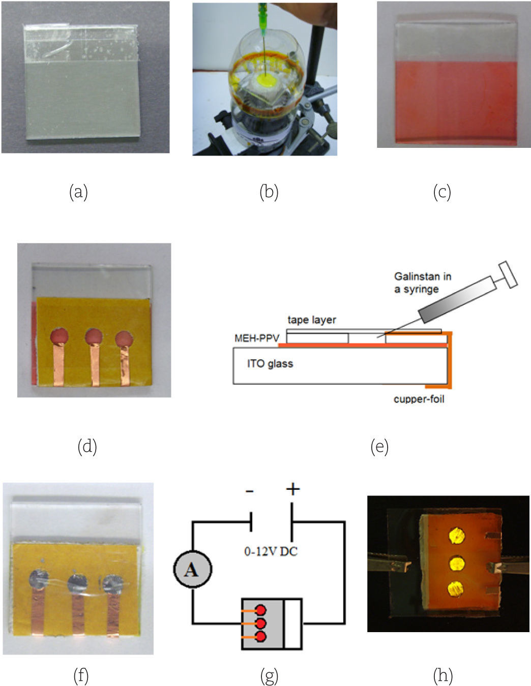
Preparing the ITO-glass: Clean the ITO-glass first with water and then with a Kleenex and acetone. From this point on avoid touching the surface of the glass with your fingers (carry it only at the edges). Measure the electrical resistance of both sides of the glass holding the multimeter leads (in a distance of 1cm) on the surface of the glass. The conducting side shows a resistance of approx. 30 Ωcm. Put a strip of adhesive tape on one end of the conducting side to mask the area, where later the anode will be connected (Fig. 4a).
- ii)
Spin-coating MEH-PPV: Warning! During the spin- coating process chloroform will evaporate. For this reason this step should be done in a fume hood and under supervision of a teacher. Use double sided tape to fix the ITO-glass with the conducting side upside onto the drilling chuck. Cut a 0.5 L PET-flask to a tube and put it over the construction to protect from splashes. Inject about 0.15-0.2mL MEH-PPV solution on the middle of the ITO-glass with the syringe (Fig. 4b). Close the front door of the fume hood as far as possible. Start the machine with the full rotation force (3000rpm) and spin-coat for about 20 sec. You should get a thin and homogeneous layer of the orange polymer onto your ITO-glass (Fig. 4c). Remove the adhesive tape from step 1.
- iii)
Preparing the cathodes: Stick three pieces of double sided tape (about 3cm×2.5cm) together and punch three holes into the layer using a hole puncher (hint: wet the pins with acetone). Put the tape onto the MEH-PPV layer, but don’t remove the rear protection sheet. Now fix three thin pieces of adhesive copper-foil as following: one end should just extend into one of the holes, while the other end is folded to the opposite side of the glass (Fig. 4d). Enclose the holes with a piece of adhesive tape to gain three cavities.
- iv)
Injection of Galinstan: Warning! Avoid touching the polymer layer with the syringe, this may cause short circuits later. Move the tip of the syringe carefully into the first cavity and gently fill up the cavity with Galinstan (Fig. 4e). If the alloy spills out, it indicates that the hole is completely filled up. Suck the excessive alloy back into the syringe. Repeat this step with the other cavities. Now close the pinholes with a piece of adhesive tape, but don’t press to strongly, otherwise Galinstan may spill out (Fig. 4f).
- v)
Connecting the OLED and recording an I/V-curve: Use an alligator clip to connect the positive pole of the power supply to the uncoated part of the ITO-glass. Connect a multimeter to the negative pole of the power supply and regulate the voltage to 2.0 V. Set the multimeter to current measurement and connect it successively to all three copper-feeds of the OLED (Fig. 4g). Dim the ambient light. Now increase the voltage in 1 V steps and note the corresponding currents of all three emission spots into a table. The strongest luminescence normally is observed at 8-9 V (Fig. 4h). End the measurement at 12 V. Disassemble the OLED as described in (vi) and plot I/V-diagrams of all three emission spots.
- vi)
Disassembly of the OLED and material disposal: Remove the upper adhesive tape first and wipe out the Galinstan with a tissue. It can be disposed of in the household garbage Now remove the double sided tape including the copper-feeds and wipe the ITO-glass under running water using your fingers. Dry the glass and clean it with acetone. It can be reused a few more times, but with every application the ITO layer will degrade. Galinstan may leave dark spots, which can be cleaned with soap and water.
![Picture story of the low-cost OLED with MEH-PPV [13].](https://static.elsevier.es/multimedia/0187893X/0000002400000001/v2_201505070135/S0187893X13731902/v2_201505070135/en/main.assets/gr4.jpeg?xkr=ue/ImdikoIMrsJoerZ+w997EogCnBdOOD93cPFbanNez443UDmD6h2cWgBNhsCiZVRhJ5LRJ6b+fqlsBl8ohvVL7XZi+ZGDwaejPRHMUOMLd96C/g4CFEQl+GiYp7UG6sxOIwHt1DjaKcdoH62Sy/kGjXc+tcFu0Iw7r6RfMiNP3bk/8pSvhER/02GnrkGkJfkt/jcc68sTYAKTGm73P061TwadgUtMO1zyTNHRJnz9fewZfM2PuS6HJFapS7cT5Rt/v3BCf/jV9/Mp3cmENNIsS7FNrm/aSxCHPIhHbCh4= "Picture story of the low-cost OLED with MEH-PPV [13].")
The injection of Galinstan is the bottleneck of the experiment 1. Any injury of the polymer layer may lead to dysfunction of the OLED due to short circuits. The following Easy-OLED does not require an injection process and can be built very simply and quickly. But notice that the OLED is less agile (because the Galinstan is not enclosed) and the emission spots cannot be controlled individually.
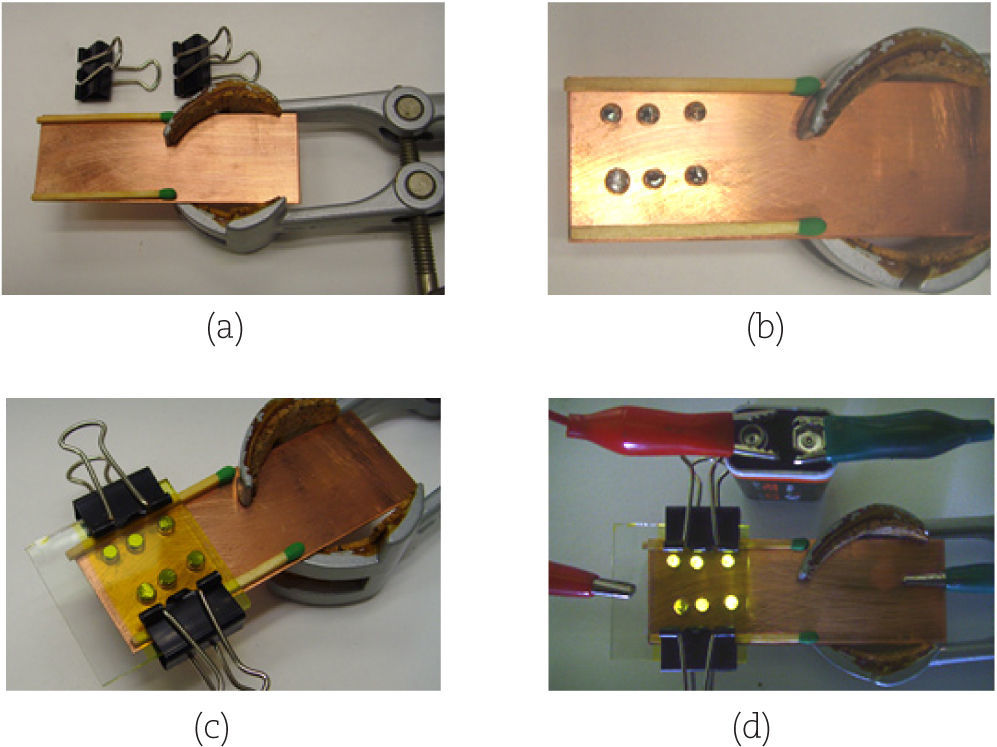
Materials: 2 matches or toothpicks as spacers, 1 metal plate (e.g. a copper or iron electrode), 1 retort clamp, 2 small foldback clips.
Prepare the ITO-glass as described in experiment 1 and spin-coat it with MEH-PPV or Superyellow.
- i)
Fixing the metal plate to the retort clamp: Fix the metal plate as shown in Fig. 5a to the retort clamp and place the matches on the edges of the metal plate as spacers.
 Figure 5.
Picture story of the Easy-OLED with Superyellow (Banerji, et al., 2012b.
(0,11MB). - ii)
Applying Galinstan and fixing the ITO-glass: Put some drops of Galinstan on the metal plate between the two matches exceeding their height (Fig. 5b). Put the ITO-glass with the coated side onto the matches, so that a close contact between Galinstan and the polymer is achieved. The uncoated part of the ITO-glass should extend the metal plate (Fig. 5c). Now fix the glass with the foldback clips.
- iii)
Connecting the Easy-OLED: Use the alligator clips to connect the positive pole of the 9 V battery with the uncoated part of the ITO-glass and the negative pole with the metal plate. Dim the ambient light and observe the luminescence for at least 30 sec. The contact spots between Galinstan and the polymer should begin to glow (Fig. 5d). You can connect the Easy-OLED to a power supply and regulate the voltage up to 12 V to get a brighter luminescence.

In the online supplemental of this article a didactical concept for the curricular integration of conducting polymers and OLEDs into chemistry classes including instruction manuals, work sheets for students and anticipated solutions is provided. The materials have been developed by our work group recently and are not tested extensively yet. In the following a short overview of the materials is given.
a)Notes for the instructorThese notes include helpful information for teachers, as for example sources of supply, advices to the experiments, safety information and didactical commentaries. Additionally a propose for a curricular integration is provided, which embeds the four OLED experiments as well as the accompanying student work sheets into a lesson of six class-sessions each of 50min of time.
b)Student handoutThe handout for the students includes printable instructions for the experiments as well as the exercise work sheets.
c)Video tutorialFor better preparation to the experiment a free video tutorial (in English) is provided on our website (Chimie und ihre didaktik, 2012a). The video explains in five parts, how the low-cost OLED (Standard-variation with FTO-glass and tape) is built. An accompanying work sheet is provided in the student handout.
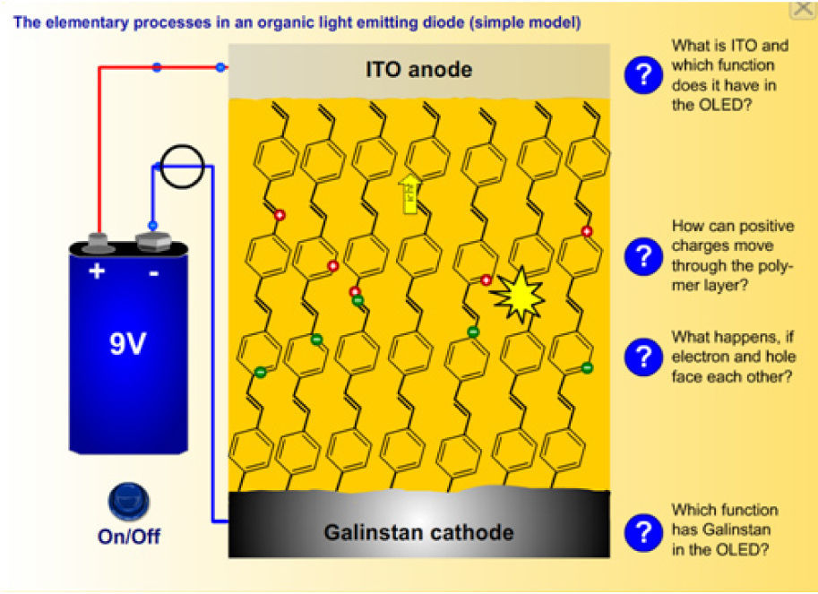
e)Flash-toolFor the evaluation of the experiments and for dealing with electroluminescence in OLEDs on different levels of abstraction we developed two interactive, self-explanatory Flash-models. The whole Flash-tool is freely available in German and English on our website (Chimie und ihre didaktik, 2012a). In the student handout work sheets are provided, which guide the learners through the animations.
The simple model (Fig. 6) shows the working principle of the self-made OLED in a simplified structure model and depicts the recombination process in detail using an energy model. It is recommended for undergraduate students and for the introduction into the principle of electroluminescence in OLEDs.
.")
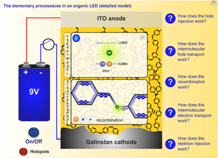
The detailed model (Fig. 7) depicts all elementary processes (charge injection, charge transport via hopping mechanism, electron-hole-recombination and exciton decay) on the structural as well as on the energetic level as depicted in Fig. 3. It is recommended for graduate or college students for a deeper understanding of electroluminescence in polymer devices.
f)Outlook.")
Conducting polymers and OLEDs are motivating topics for young people, since they face high-tech products using these technologies in their everyday life. The experiments for low-cost OLEDs are applicable for use in chemistry or physics classes or in other projects at high school.
The self-made OLED can also be operated in opposite direction as a prototype of a photovoltaic plastic cell. We could measure stable voltages of up to 1V with the device based on Superyellow. A low-cost bulk-heterojunction PV cell based on MEH-PPV and PCBM was reported by Maldonado et al. (2008). Further research on plastic solar cells and the development of adequate educational materials will be accomplished in our workgroup soon.
We have developed an interdisciplinary workshop on innovative polymers for our local student-lab “Chemie-Labothek”, which cross-links the subjects chemistry, physics and computer science. The aim of the workshop is to explore and understand the main principle of an OLED display, starting from the basics on conventional polymers via the electroluminescence in conjugated polymers to the interconnection of three OLED spots to a matrix-display with an individually programmed light pattern. For further information on this project visit our website (Chimie und ihre didaktik, 2012b).
g)HazardsThere are no significant hazards reported for MEH-PPV or Superyellow. However the solutions are based on noxious solvents, so spin-coating must be carried out in a fume hood. The plastic flask does not only protect from splashes, but also catches the glass if it is released during spin-coating. So never spin-coat without protection.
Cover the work space with news paper before working with Galinstan. Spills of the alloy can be carefully sucked back into the syringe or cleaned up with soap and water. There are no significant hazards reported for Galinstan or the gallium-indium eutectic.
All elementary processes mainly take place between the upper edge of the valance band, can be regarded as HOMO, and the lower edge of the conduction band, can be regarded as LUMO, of the polymer.
Although the used conductive glass is based on FTO (fluorine doped tin oxide), we recommend establishing the term ITO to the students. Indium doped tin oxide (ITO) is still the standard material for transparent electrodes in optoelectronics and the acronym is widely spread in literature and school books.
Available at: http://www.chemiedidaktik.uni-wuppertal.de/download/OLED_EQ.zip Learning About Materials Science by Making Organic Light-Emitting Electrochemical Thin Film Devices, by H. Sevian, S. Müller, H. Rudmann, M. F. Rubner Supplementary Material for the 2004 paper of the same authors in J. Chem. Educ.