


Three-phase multipulse AC–DC converters (MPC) are developed for improving power quality to reduce harmonics in ac mains and ripples in dc output. This study, based on technical and economic factors, compares different autotransformer-based 30-pulse AC–DC converters. In this paper, the comparison of two topologies of autotransformer-based 30-pulse AC–DC converter has been presented. In topology A, three-phase AC voltages are given to the autotransformer, which produces five sets of three-phase voltage and, in topology B, three-phase AC voltages are given to the autotransformer, which produces three sets of five-phase voltages of same magnitude and distributed in time through phase shifts of 12°. Topology A included polygon, hexagon, star, fork, and T-connected autotransformer-based 30-pulse AC–DC converters, and topology B Included polygon, and T-connected autotransformer-based 30-pulse AC–DC converters. These converters have been implemented and simulation using Matlab/Simulink software for similar ratings under different load conditions has been performed. A set of power-quality indices on input ac mains and on a dc bus for a DTCIMD fed from different 30-pulse AC–DC converters is given to compare their performance. Economic comparison of 30 pulse AC–DC converters is based on the apparent power (kVA) ratings of the different autotransformer for 30 pulse AC–DC converters.
Recent advances in solid state conversion technology have led to the proliferation of variable frequency induction motor drives (VFIMD's) that are used in several applications such as air conditioning, blowers, fans, pumps for waste water treatment plants, textile mills, rolling mills, etc. (Bose, 1998). The most practical technique in VFIMD's is direct torque controlled strategy in that it offers better performance rather than the other control techniques. Direct Torque controlled technique is implemented in voltage source inverter which is mostly fed from six-pulse diode bridge rectifier, Insulated gate bipolar transistors (IGBT's) are employed as the VSI switches. The most important drawback of the six-pulse diode-bridge rectifier is its poor power factor injection of current harmonics into ac mains. The circulation of current harmonics into the source impedance yields in harmonic polluted voltages at the point of common coupling (PCC) and consequently resulting in undesired supply voltage conditions for costumers in the vicinity. The value of current harmonic components which are injected into the grid by nonlinear loads such as DTCIMD's should be confined within the standard limitations. The most prominent standards in this field are IEEE standard 519 (IEEE Standard 519-2014 (2014) and the International Electro technical Commission (IEC) 61000-3-2 (IEC Standard 61000-3-2: 2004 (2004).
Arc furnaces generate more harmonic current distortion and Static Power Converters (SPC's) are the harmonic current source with the widest distribution in electrical systems. For DTCIMD's one effective solution is to employ multipulse AC–DC converters. These converters are based on either phase multiplication or phase shifting or pulse doubling or a combination (Abdollahi, 2012h; Abdollahi & Jalilian, 2011, 2012b; Paice, 1996; Singh, Bhuvaneswari, & Garg, 2007b). Although, in the conditions of light load or small source impedance, line current total harmonic distortion (THD) will be more than 5% for up to 18-pulse AC–DC converters (Singh, Bhuvaneswari, & Garg, 2007c; Singh, Garg, & Bhuvaneswari, 2007). A hexagon-connected autotransformer-based 20-pulse AC–DC converter is reported in (Abdollahi, 2012a) which has THD variation of 5.18–7.20% from full-load to light-load (20% of full-load). A zigzag-connected autotransformer-based 24-pulse AC–DC converter is reported in (Abdollahi, 2015a) which has THD variation of 3.95–5.85% from full-load to light-load (20% of full-load). Another T-connected autotransformer-based 24-pulse AC–DC converter has also been presented in Singh, Bhuvaneswari, and Garg (2006a), however, the THD of the supply current with this topology is reported to vary from 2.46% to 5.20% which is more than 5% when operating at light load.
The 36-pulse one was designed for vector controlled induction motor drives in Singh and Gairola (2007) which has THD variation of 2.03–3.74% from full-load to light-load (20% of full-load) respectively but the dc link voltage is higher than that of a 6-pulse diode bridge rectifier, thus making the scheme nonapplicable for retrofit applications. The delta/polygon-connected transformer-based 36-pulse AC–DC converter for power quality improvement in (Abdollahi, 2012d) which has THD variation of 2.92–3.89% from full-load to light-load (20% of full-load) respectively and delta/fork, and delta/hexagon-connected transformer-based 36-pulse AC–DC converters have been reported (Abdollahi, 2012e, 2015b) for reducing the total harmonic distortion (THD) of the ac mains current. But these topologies require higher rating magnetics, resulting in the enhancement of capital cost. However, these topologies increase the rating of magnetic parts, which finally affects the total cost of the project. The magnetic rating of the multi-pulse AC–DC converter based on transformer topology is more than 100% of the load rating. In contrast, the autotransformer-based configurations (Paice, 1996) reduce the ratings of magnetic parts. This is true because of the fact that in this topology, only a portion of KVA rating of the induction motor should be beard by the magnetic coupling parts. Therefore, autotransformer-based configurations could significantly reduce the size and proportionally the weight of the transformer. Abdollahi (2012f, 2015c, 2012g) proposed tapped delta, polygon, T-connected autotransformer-based 36-pulse AC–DC converters, which supply induction motor drives to improve power quality at the PCC. Although increasing the pulse number can bring dramatic improvement in different power quality indices, it will also make the autotransformer configuration become cumbersome and more diode bridge rectifiers will be required, leading to increased components and cost in the overall AC–DC converter system.
In this paper, the comparison of two topologies of autotransformer-based 30-pulse AC–DC converter has been presented. Topology A included polygon (Singh, Garg, & Bhuvaneswari, 2006), hexagon (Singh, Bhuvaneswari, & Garg, 2007a), star (Singh, Bhuvaneswari, Garg, & Chandra, 2006), fork (Abdollahi & Jalilian, 2012a), and T (Singh, Bhuvaneswari, & Garg, 2006b)-connected autotransformer-based 30-pulse AC–DC converters and topology B Included polygon (Abdollahi, 2012b), and T (Abdollahi, 2012c)-connected autotransformer-based 30-pulse AC–DC converters. This study, based on technical and economic factors, compares different autotransformer-based 30 pulse AC–DC converters. Simulation results of six-pulse and different 30-pulse AC–DC converters feeding a DTCIMD load are scheduled and various quality criteria such as THD of ac mains current, power factor, displacement factor, distortion factor, and THD of the supply voltage at PCC are compared. Economic comparison of different 30 pulse AC–DC converters is based on the apparent power (kVA) ratings of the 30 pulse AC–DC converters.
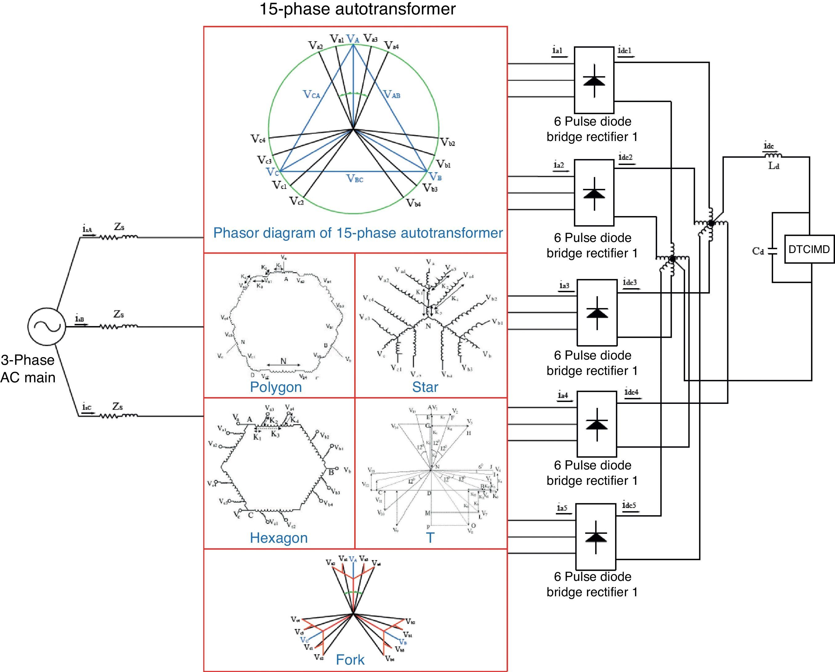
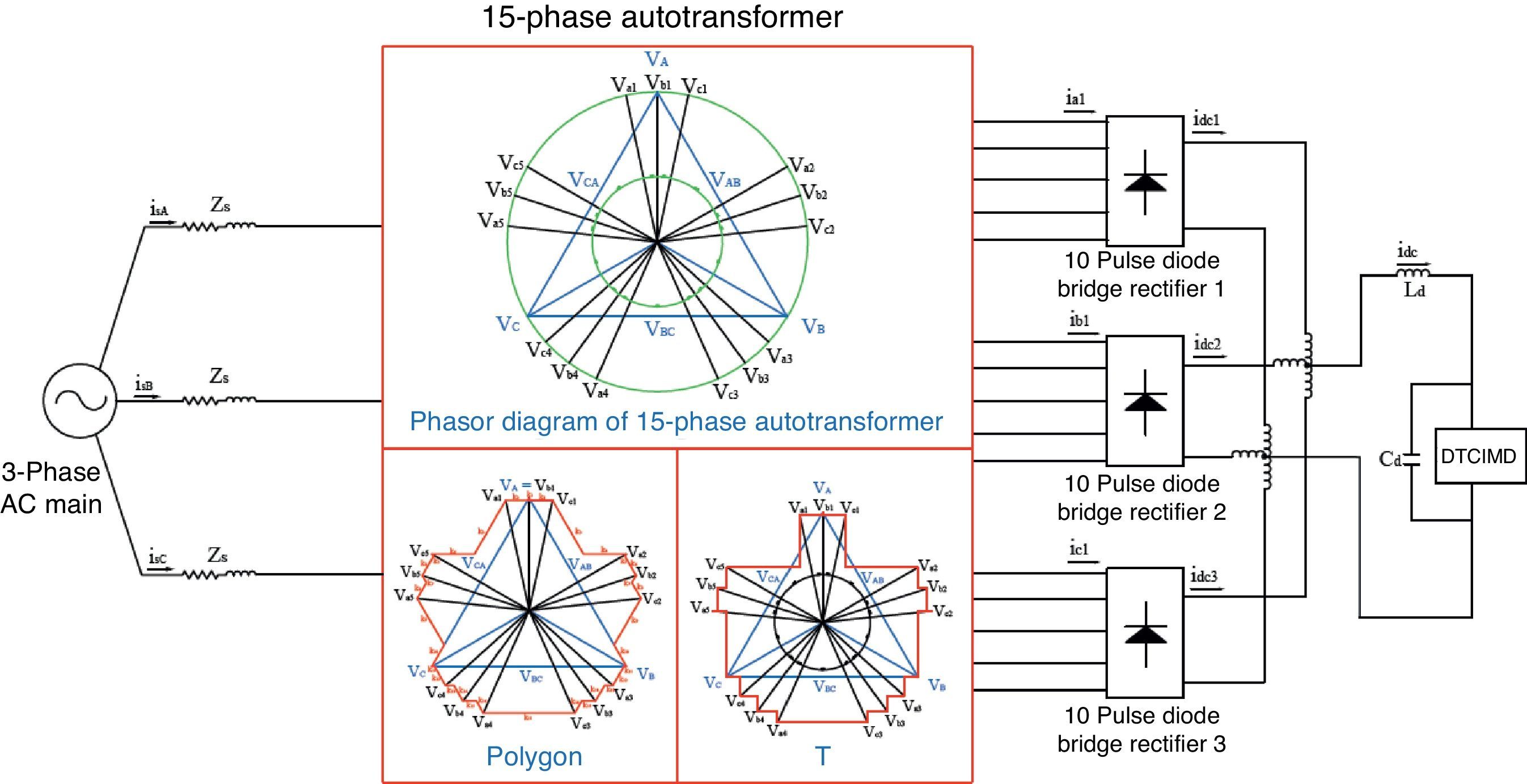
230-Pulse AC–DC converterIn this paper, the comparison of two topologies of autotransformer-based 30-pulse AC–DC converter has been presented. In topology A, three-phase AC voltages are given to the autotransformer, which produces five sets of three-phase voltages, as shown in Fig. 1, and in topology B, three-phase AC voltages are given to the autotransformer, which produces three sets of five-phase voltages of same magnitude and distributed in time through phase shifts of 12°, as shown in Fig. 2. Topology A included polygon, hexagon, star, fork, and T-connected autotransformer-based 30-pulse AC–DC converters and topology B included polygon, and T-connected autotransformer-based 30-pulse AC–DC converters.
.")
.")
In order to implement a 30-pulse AC–DC converter (topology A) through paralleling five bridge rectifiers, i.e. five 6-pulse rectifiers, five sets of three-phase voltages with a phase difference of 120° between the voltages of each group and 12° between the same voltages of the five groups are required. Accordingly, each bridge rectifier consists of 3 common-anode and 3 common-cathode diodes (five 3-leg rectifiers). Autotransformer connections and its phasor diagram which shows the angular displacement of voltages are illustrated in Fig. 1. The aforementioned five voltage sets are called as (Va1, Vb1, Vc1) and (Va2, Vb2, Vc2) and (Va, Vb, Vc) and (Va3, Vb3, Vc3) and (Va4, Vb4, Vc4) that are fed to rectifiers I, II, III, IV and V, respectively. The same voltages of the five groups, i.e. Vai, are phase displaced of 12°. Va1 and Va3 has a phase shift of +12° and −12° from the input voltage of phase A, respectively. According to phasor diagram, the 3-phase voltages are made from ac main phase and line voltages with fractions of the primary winding turns which are expressed with the following relationships.
In order to implement a 30-pulse AC–DC converter (topology B) through paralleling three bridge rectifiers, i.e. three 10-pulse rectifiers, three sets of 5-phase voltages with a phase difference of 72° between the voltages of each group and 12° between the same voltages of the three groups are required. Accordingly, each bridge rectifier consists of 5 common-anode and 5 common-cathode diodes (three 5-leg rectifiers). Autotransformer connections and its phasor diagram which shows the angular displacement of voltages are illustrated in Fig. 2. The aforementioned three voltage sets are called as (Va1, Va2, Va3, Va4, Va5) and (Vb1, Vb2, Vb3, Vb4, Vb5) and (Vc1, Vc2, Vc3, Vc4, Vc5) that are fed to rectifiers I, II and III, respectively. The same voltages of the three groups, i.e. Vai, Vbi, and Vci, are phase displaced of 12°. Vb1 and Vc1 has a phase shift of +12° and −12° from the input voltage of phase A, respectively. According to phasor diagram, the 5-phase voltages are made from ac main phase and line voltages with fractions of the primary winding turns which are expressed with the following relationships.
3Matlab-based simulationThe designed configurations were simulated using Matlab/Simulink software and power system block set (PSB) toolbox. In this model, a three-phase 460V and 60Hz network is utilized as the supply for the 30-pulse converters. The designed autotransformer is modeled via three multi-winding transformers. Multi-winding transformer block is also used to model IPT. At the converter output, a series inductance (L) and a parallel capacitor (C) as the dc link are connected to an IGBT-based voltage source inverter (VSI). VSI drives a squirrel cage induction motor employing direct torque controlled strategy. The simulated motor is 50hp (37.3kW), 4-pole, and Y-connected. Detailed data of the motor are listed in Appendix A. Simulation results are depicted in Figs. 3–5. Power quality parameters are also listed in Table 1 for 6-pulse, and different 30-pulse AC–DC converters. The rating of input transformer is calculated based on the simulated rms values of the voltage and current.
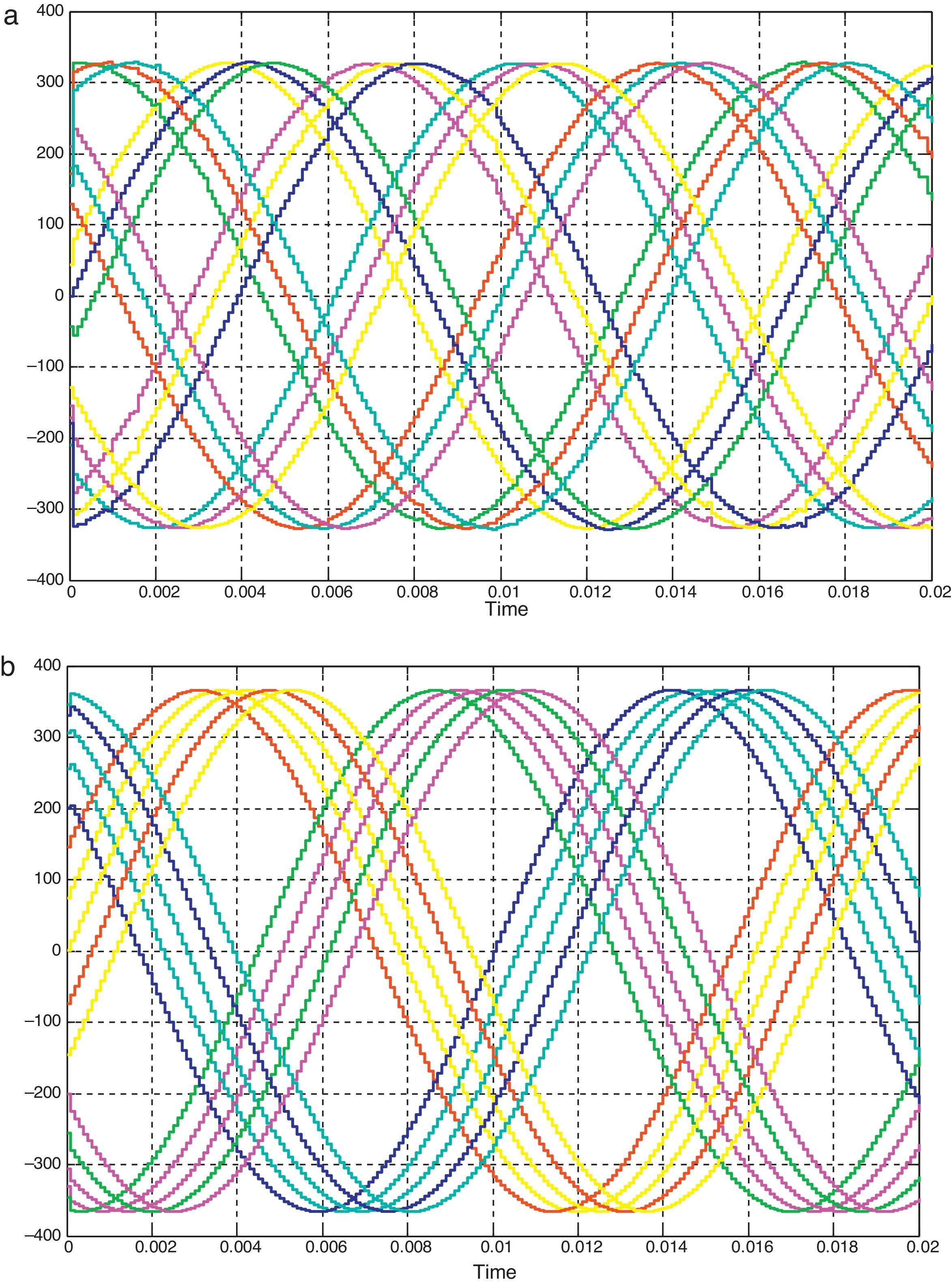
 topology A (three groups of 5-phase voltage), and (b) topology B (five groups of 3-phase voltage).")
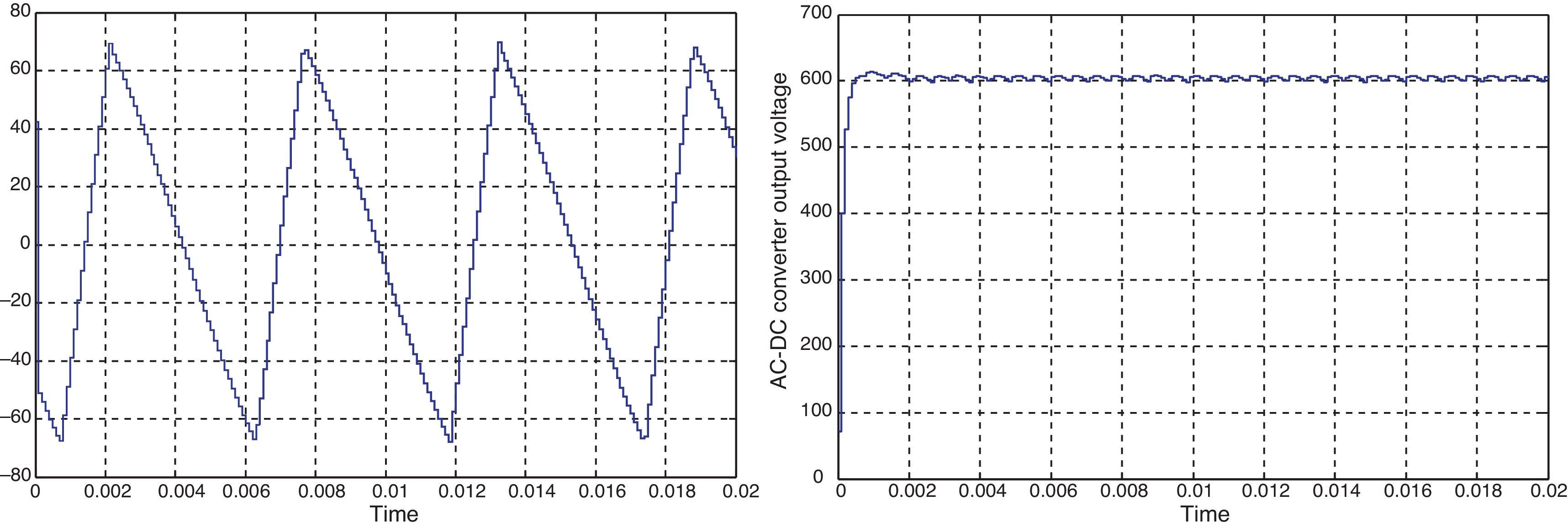
 Voltage waveform across the interphase transformer and (b) 30-pulse AC–DC converter output voltage.")
 sex, (b) polygon(A), (c) hexagon, (d) star, (e) fork, (f) T(A), (g) polygon(B), (h) T(B) autotransformer based 30-pulse AC–DC converters at light load and full load.")
 sex, (b) polygon(A), (c) hexagon, (d) star, (e) fork, (f) T(A), (g) polygon(B), (h) T(B) autotransformer based 30-pulse AC–DC converters at light load and full load.")
 sex, (b) polygon(A), (c) hexagon, (d) star, (e) fork, (f) T(A), (g) polygon(B), (h) T(B) autotransformer based 30-pulse AC–DC converters at light load and full load.")
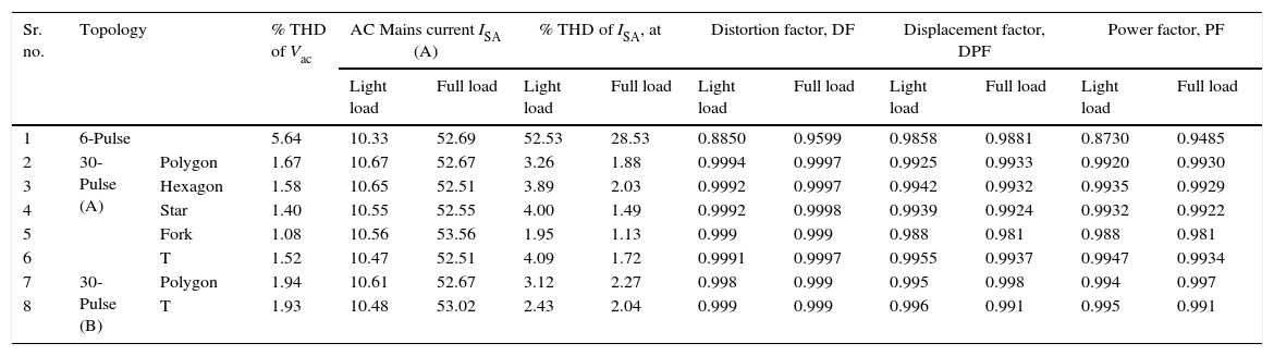
Comparison of power quality parameters of different topologies.
| Sr. no. | Topology | % THD of Vac | AC Mains current ISA (A) | % THD of ISA, at | Distortion factor, DF | Displacement factor, DPF | Power factor, PF | ||||||
|---|---|---|---|---|---|---|---|---|---|---|---|---|---|
| Light load | Full load | Light load | Full load | Light load | Full load | Light load | Full load | Light load | Full load | ||||
| 1 | 6-Pulse | 5.64 | 10.33 | 52.69 | 52.53 | 28.53 | 0.8850 | 0.9599 | 0.9858 | 0.9881 | 0.8730 | 0.9485 | |
| 2 | 30-Pulse (A) | Polygon | 1.67 | 10.67 | 52.67 | 3.26 | 1.88 | 0.9994 | 0.9997 | 0.9925 | 0.9933 | 0.9920 | 0.9930 |
| 3 | Hexagon | 1.58 | 10.65 | 52.51 | 3.89 | 2.03 | 0.9992 | 0.9997 | 0.9942 | 0.9932 | 0.9935 | 0.9929 | |
| 4 | Star | 1.40 | 10.55 | 52.55 | 4.00 | 1.49 | 0.9992 | 0.9998 | 0.9939 | 0.9924 | 0.9932 | 0.9922 | |
| 5 | Fork | 1.08 | 10.56 | 53.56 | 1.95 | 1.13 | 0.999 | 0.999 | 0.988 | 0.981 | 0.988 | 0.981 | |
| 6 | T | 1.52 | 10.47 | 52.51 | 4.09 | 1.72 | 0.9991 | 0.9997 | 0.9955 | 0.9937 | 0.9947 | 0.9934 | |
| 7 | 30-Pulse (B) | Polygon | 1.94 | 10.61 | 52.67 | 3.12 | 2.27 | 0.998 | 0.999 | 0.995 | 0.998 | 0.994 | 0.997 |
| 8 | T | 1.93 | 10.48 | 53.02 | 2.43 | 2.04 | 0.999 | 0.999 | 0.996 | 0.991 | 0.995 | 0.991 | |
Fig. 3(a) depicts three groups of 5-phase voltage waveforms with a phase shift of 12° between the same voltages of each group (topology A), and Fig. 3(b) depicts five groups of 3-phase voltage waveforms with a phase shift of 12° between the same voltages of each group (topology B). The voltage across the interphase transformer (shown in Fig. 4(a)) has a frequency equal to 3 times that of the supply which results in a significant reduction in volume and cost of magnetics. The 30-pulse converter output voltage (shown in Fig. 4(b)) is almost smooth and free of ripples and its average value is 608.9V which is approximately equal to the DC link voltage of a 6-pulse rectifier (607.6V). This makes the 36-pulse converters suitable for retrofit applications.
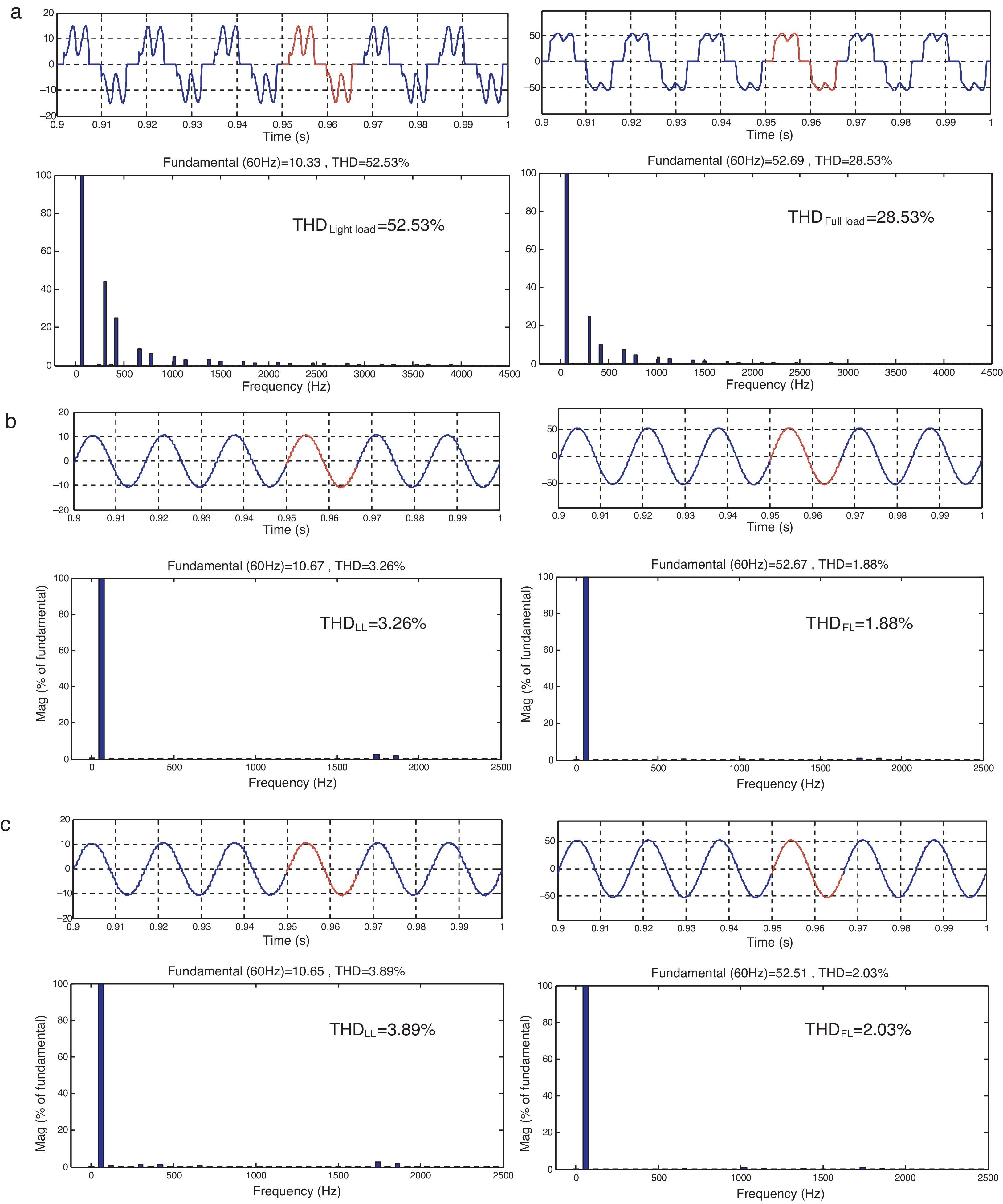
Input current waveforms and its harmonic spectrum of the 6-pulse and different 30-pulse converters (polygon(A), hexagon, star, fork, T(A), polygon(B), and, T(B)) extracted and shown in Fig. 5, respectively. The current THD of the device can be assessed in order to check if its harmonic spectrum can contribute to achieve the IEEE 519 limits. These harmonic spectrums are obtained when induction motor operates under light load (20% of full load) and full load conditions. Obviously, for 6-pulse converter, fifth and seventh order harmonics are dominant. Hence, input current THD of this converter will be relatively a large amount and is equal to 28.53% and 52.53% for full load and light load conditions that are not within the standard margins. Moreover, the power factor at full load is 0.937, which deteriorates to 0.848 as the load is reduced. These results show that there is a need for improving the power quality at the ac mains using some harmonic mitigators which can easily replace the existing 6-pulse converter. The supply current waveform along with its harmonic spectrum of fork autotransformer-based 30-pulse AC–DC converter at light load and full load is shown in Fig. 5(e), which shows that at full load condition, the THD of the ac mains current is 1.13% and at light load condition, the THD of the ac mains current is 1.95%. The simulation results of different autotransformer-based 30-pulse AC–DC converter fed DTCIMD are shown in Fig. 5 at full load and light load (20%). Table 1 shows a comparative study of different power-quality indices such as THD of supply current and voltage (THDi and THDv), displacement power factor (DPF), distortion factor (DF), and power factor (PF) of a DTCIMD fed from a 6-pulse converter and different autotransformer-based 30-pulse converters for different loading conditions. Results show that the input current corresponding to the different autotransformer-based 30-pulse AC–DC converter configuration has an almost unity power factor. The different autotransformer-based 30-pulse AC–DC converters gives the same dc-link voltage as that of a 6-pulse diode bridge rectifier, making it suitable for retrofit applications. Furthermore, in the worst case (light loads) the current THD has reached below 4% for the different autotransformer-based 30-pulse AC–DC converters.
5Apparent power ratingsThe apparent power (kVA) ratings of the different autotransformer and tapped IPT, for 36-pulse configuration are calculated using the following Eq. (1):
where Vwinding is the rms voltage across each part of the autotransformer, and IPT windings and Iwinding indicates the full load current of the same windings. These rms values are obtained by simulations of 50hp (37.3kW) load as listed in Table 2.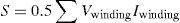
Comparison of magnetic rating for 30-pulse converters based on autotransformers.
| Transformer type | Main transformer rating (% of load) | Interphase reactor rating (% of load) | Total magnetic rating (% of load) |
|---|---|---|---|
| Topology A | |||
| Polygon(A) | 30.5 | 7.5 | 38 |
| Hexagon | 24.8 | 5.8 | 30.6 |
| Star | 51.3 | 7.45 | 58.75 |
| Fork | 43.5 | 6.4 | 49.9 |
| T(A) | 30.0 | 6.2 | 36.2 |
| Topology B | |||
| Polygon(B) | 43.8 | 5.6 | 49.4 |
| T(B) | 45.65 | 6.92 | 52.57 |
The calculated ratings are 11,376.5 VA and 2792.5 VA for polygon(A) (topology A) autotransformer and IPT, respectively, which are 30.5% and 7.5% of the load power rating (37.3kW), respectively. It means that the required magnetic rating of the polygon(A) topology is about 38% of the load rating. The calculated ratings are 9250.4 VA and 2163.4 VA for hexagon autotransformer and IPT, respectively. The ratings of input hexagon autotransformer and IPT are obtained, and these are 24.8%, and 5.8%, respectively of the load rating (37.3kW). As mentioned previously, the required magnetic rating of the hexagon topology is 30.6% of the load rating.
The calculated ratings are 19,134.9 VA and 2778.85 VA for star autotransformer, and IPT, respectively, which are 51.3% and 7.45% of the load power rating (37.3kW), respectively. It means that the required magnetic rating of the star topology is about 58.75% of the load rating. The calculated ratings are 16,225.5 VA and 2387.2 VA for fork autotransformer, and IPT, respectively, which are 43.5% and 6.4% of the load power rating (37.3kW), respectively. It means that the required magnetic rating of the fork topology is about 49.9% of the load rating. The calculated ratings are 11,190 VA and 2312.6 VA for T(A) autotransformer, and IPT, respectively, which are 30.0% and 6.2% of the load power rating (37.3kW), respectively. It means that the required magnetic rating of the T(A) topology is about 36.2% of the load rating.
The calculated ratings are 16,337.4 VA and 2088.8 VA for polygon(B) autotransformer, and IPT, respectively, which are 43.8% and 5.6% of the load power rating (37.3kW), respectively. It means that the required magnetic rating of the polygon(B) topology is about 49.4% of the load rating. The calculated ratings are 17,027.45 VA and 2581.16 VA for T(B) autotransformer, and IPT, respectively, which are 45.65% and 6.92% of the load power rating (37.3kW), respectively. It means that the required magnetic rating of the T(B) topology is about 52.57% of the load rating.
It can also be obtained from simulations that the hexagon 30-pulse harmonic mitigator for retrofit applications needs totaling all the required magnetics of 11.413kVA, that is to say, only 30.6% of the load power rating. In comparison with the total magnetics ratings of conventional polygon(A) autotransformer-based 30-pulse (38%) and star autotransformer (58.75%), fork autotransformer (49.9%), T(A) autotransformer (36.2%), polygon(B) autotransformer (49.4%), T(B) autotransformer (52.57%)-based 30-pulse AC–DC converters, the total ratings of magnetics of the hexagon autotransformer 30-pulse rectifier system is much less. The low equivalent kVA rating of the hexagon autotransformer has resulted in a system of lower cost compared with other types of autotransformer configuration-based 30-pulse AC–DC converters. The detailed comparison results are tabulated in Table 2.
The T-connected autotransformer configuration requires two single-phase transformers, which is more economical (in weight and volume) as compared with other topologies using three single-phase transformers. It further results in savings in volume, size and finally the cost of the drive. Also, the T(A) 30-pulse harmonic mitigator needs totaling all the required magnetics of 13.502kVA, that is to say, only 36.2% of the load power rating. The low equivalent kVA rating and low weight and volume of the T(A) autotransformer has resulted in a system of lower volume, weight, losses and cost compared with other types of autotransformer configuration-based 30-pulse AC–DC converters.
6ConclusionsThe different 30-pulse AC–DC converters are capable of eliminating up to 27th harmonics in the input supply current. The different rectifier has the flexibility to vary the dc link voltage, simply by changing the ratio of number of turns of the transformer, which makes it suitable for retrofit applications. The simulation results have shown that the THD of input current remains below 4.0% and the power factor is always above 0.99 in the wide operating range of the loads to the different autotransformer-based 30-pulse AC–DC converter configuration.
Results show that even under load variations, the fork autotransformer-based 30-pulse converter has an improved performance and the current THD is always less than 2% for all loading conditions. The low equivalent kVA rating (30.6%) of the hexagon autotransformer has resulted in a system of lower cost compared with other types of autotransformer configuration-based 30-pulse AC–DC converters. As well as the low equivalent kVA rating (36.2%) and low weight and volume of the T(A) autotransformer has resulted in a system of lower volume, weight, losses and cost compared with other types of autotransformer configuration-based 30-pulse AC–DC converters.
Conflict of interestThe authors have no conflict of interest to declare.
Three-phase squirrel cage induction motor—50hp (37.3kW), three phase, four pole, Y-connected, 460V, 60Hz. Rs=0.0148Ω; Rr=0.0092Ω; Xls=1.14Ω; Xlr=1.14Ω, XLm=3.94Ω, J=3.1kgm2.
Controller parameters: PI controller Kp=300; Ki=2000.
DC link parameters: Ld=2mH; Cd=3200μF.
Source impedance: Zs=j0.1884Ω (=3%).
Peer Review under the responsibility of Universidad Nacional Autónoma de México.