


Compressor and counter cells are the basic blocks used to accumulate the partial products in a multiplication process. In this paper, novel high speed and low power carbon nanotube counter cells are suggested. The efficiency of circuits is improved by using carbon nanotube field-effect transistors (CNFETs). The proposed designs are 4-to-3, 5-to-3, 6-to-3, and 7-to-3 counters. Using HSPICE, these proposed designs are simulated at different conditions. Simulation results confirm that the proposed designs are the fastest counters with lowest PDP in different working circumstance.
Among the most basic blocks in computer arithmetic are multipliers, which are commonly used in different digital signal processors. In different applications of computing systems there is growing demands for high-speed multipliers, such as computer graphics, image processing, scientific calculation, and so on (Azarderakhsh & Reyhani-Masoleh, 2013; Bagherizadeh, Gerami, & Eshghi, 2014; Rodríguez-Reséndiz, Gutiérrez-Villalobos, Duarte-Correa, Mendiola-Santibañez, & Santillán-Méndez, 2012). The speed of a multiplier specifies how fast a processor will run. Designers are now more focused on low power consumption and high speed processors. A multiplication operation conventionally involves three operational stages: generation of partial products, reduction of partial products to two additive operands, and finally, carry propagation addition. The partial product reduction stage is respectful for a main part of the total multiplication delay, power and area (Waters & Swartzlander, 2010). Hence, in order to acquire partial products, compressor and counter cells usually implement this stage because they contribute to the reduction of the partial products and the critical path (Jaberipur & Kaivani, 2009). Counters are much faster than conventional adders because they could act without carry signal along their digital stages. Counters are the basic blocks, which are used to acquire the partial products in the multiplication process (Deng & Chen, 2013). Thus, improving the power performance of these structures could lead to remarkable saving of the power used by the entire multiplier. Because of the miniaturization of the transistors, it is possible to increase the number used in each circuit. This nano level reduction will cause some acute problems such as short channel effects, remarkable gate control degradation and high leakage power consumption. A solution to these problems is using carbon nanotube field effect transistors (CNFETs) (Bagherizadeh & Eshghi, 2011a, 2011b; Perri & Corsonello, 2012). One of the most considerable properties of this type of transistor is the ability of having optional threshold voltage by changing the diameters of the nanotubes. This property makes CNFETs suitable for designing circuits with multiple threshold voltage ranges (Bagherizadeh & Eshghi, 2011a, 2011b).
In this paper, four novel high speed and low PDP CNFET-based counters are proposed. These counters are capable of adding four, five, six or seven bits per decade, and generate 3 outputs. CNFETs with different threshold voltages are used to design our proposed counters.
In the remainder of this paper, in Section 2, a brief review of the CNFET technology is presented. In the next section related works are discussed. The proposed CNFET-based counter cells are presented in Section 4. Experimental results, analyses and comparisons are presented in Section 5, and finally, Section 6 concludes the paper.
2Carbon nanotube field effect transistors (CNFETs)A carbon nanotube (CNT) is an allotrope of carbon with a tubal nanostructure. Transistors, which have carbon nanotubes as their channel, are called carbon nanotube field-effect transistors (Mehrabani & Eshghi, 2015). CNTs have particular properties that make them promising to be used in the field of integrated circuits. The most important and remarkable feature of CNFETs is their spectacular capability in current driving or current carrying, and experiments have shown that CNFETs are the best for this aim (Bagherizadeh & Eshghi, 2011a, 2011b; Lin, Kim, & Lombardi, 2009). Without any extra power overhead, CNFETs could operate five times faster than CMOS in the best case. Another fundamental feature of CNTFETs is their varied behavior in manipulating the threshold voltage (Vth) by adopting an appropriate diameter for CNTs (Bagherizadeh & Eshghi, 2011a, 2011b).
Multi-walled nanotubes (MWNT) consist of multiple rolled layers (concentric tubes) of graphite. A single-wall CNT consists of a tube-shaped wall which is made of graphite with the diameter of 1–2nm. A multi-walled CNT has a thinner wall. The walls of the tubes are 34nm each. The outer wall diameter of the multi-walled CNT is 2–25nm (Mehrabi, Mirzaee, Moaiyeri, Navi, & Hashemipour, 2013).
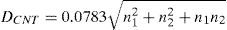
A CNT is described by its chiral vector. The chirality vector is defined by an ordered pair (n1, n2) that characterize many electrical and physical properties of the carbon nanotube (Bagherizadeh & Eshghi, 2011a, 2011b; Mehrabi, Mirzaee, Zamanzadeh, Navi, & Hashemipour, 2013; Mehrabi, Navi, & Hashemipour, 2013; Mehrabi, Mirzaee, Moaiyeri, et al., 2013). It is calculated using Eq. (1):
where [â1, â2] are the lattice unit vectors and n1, n2 are positive integers which specify the tube's structure. The single-walled carbon nanotubes (SWCNT) could be a metal or a semiconductor, if n1−n2≠3k(k∈Z), then the SWCNT is a semiconductor; otherwise it is a metal.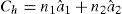
The diameter of the CNT is calculated using Eq. (2) (Alkaldy, Navi, & Sharifi, 2014; Bagherizadeh & Eshghi, 2011a, 2011b; Mehrabani & Eshghi, 2015).
The threshold voltage of a CNT channel is approximated as the inverse function of diameter and could be computed as Eq. (3). A special threshold voltage of a CNFET could be obtained by a suitable diameter (Alkaldy et al., 2014).
where parameter a (≈0.249nm) is the carbon-to-carbon atom distance, Vπ(≅3.033eV) is the carbon π–π bond energy in the tight bonding model, and e is the unit electron charge, Eg is the band gap, and DCNT is the CNT diameter.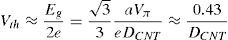
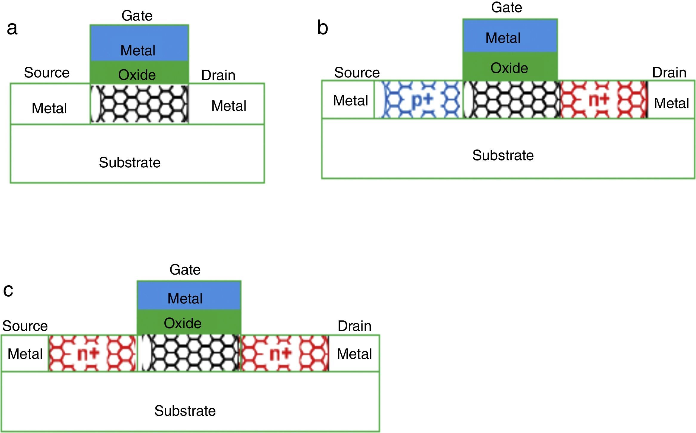
There are three kinds of CNFET: The first kind is the MOSFET-like CNFET (which contains the p-type CNFET and n-type CNFET), which operates in a unipolar mode; the second kind is the Schottky barrier (SB) CNFET, which shows ambipolar characteristics, but because of the SB element, it is not appropriate for high performance applications; the third kind of CNFET, suitable for low power applications, is the band-to-band tunneling CNFET that has obviously low current in its active mode (Alkaldy et al., 2014). Fig. 1 shows three kinds of CNFETs. A CNFET has relatively low off-current while the transistor is inactive; in other words, when the CNFET is off, leakage power consumption is low. CNFETs have electrical specifications and structure similar to MOSFETs, which facilitates the exploitation and reuse of previous MOSFET-based architectures and manufacturing processes (Bagherizadeh & Eshghi, 2011a, 2011b).
3Compresssor and counter cells in the literarure SB-CNFET, (b) T-CNFET, and (c) MOSFET-like CNFET.")
In this section, some of the compressor and counter cells which are presented in the literature are discussed.
3.1Compressor cellsFor different compressor cells, different designs of high performance and low power have been presented. In this section, some of these compressors are reviewed.
A 3-to-2 compressor applies three inputs, X1, X2, and X3 and produces two outputs, SUM and CARRY. This cell could also be considered as a full adder cell when the third input is the carry input from the previous compressor block, or X3=Cin. In the literature, there are different implementations of a full adder optimized for one or more figures of merits, delay, power dissipation, and power-delay product (PDP) (Bagherizadeh & Eshghi, 2011a, 2011b; Mehrabi, Mirzaee, Zamanzadeh, et al., 2013; Mehrabi, Navi, et al., 2013; Mehrabi, Mirzaee, Moaiyeri, et al., 2013).
A 4-to-2 compressor compresses five partial products bits into three. This compressor has four inputs X1, X2, X3 and X4 and two outputs, SUM and CARRY along with a CARRY-IN (CIN) and a CARRY-OUT (COUT). The CIN input is the output from the previous lower significant compressor. The COUT is the output to the compressor in the next significant stage. Using two 3-to-2 compressors in series, a 4-to-2 compressor could be set up as well that involves a critical path delay of four XORs. Different alternative implementations using XOR gates and MUX are described in Pishvaie, Jaberipur, and Jahanian (2012), Bahrepour and Sharifi (2013).
A 5-to-2 compressor block has five inputs X1, X2, X3, X4, X5, and two outputs, SUM and CARRY, along with two input carry bits (CIN1, CIN2) and two output carry bits (COUT1,COUT2). The input carry bits are the outputs from the previous less significant compressor block. The output carries are passed on to the next high significant compressor block. In addition, a 5-to-2 compressor could be set up using 3-to-2 compressors. It consists of three 3-to-2 compressors (full adders) in series (Chang, Gu, & Zhang, 2004; Najafi, Timarchi, & Najafi, 2014). This architecture has a critical path delay of six XOR gates.
In Qi, Kim, and Choi (2012), in order to reduce the power delay product of a multiplier, different types of the MUX-based compressor cells are presented. These designs are for 4-to-2, 5-to-2, and 7-to-2 compressors. The MUX-based compressor cells use much less transistors than the full adder based compressors.
3.2Counter cellsOne of the main components to construct high performance DSP units is the parallel counter. As the multiplier size increases, designing optimized wider counters are critical for its performance (Bagherizadeh et al., 2014; Parandeh-Afshar, Verma, Brisk, & Ienne, 2010). A counter is the hardware that counts the number of logic ‘1’ of inputted bits. Counters are different from compressors. The essential difference between a counter and a compressor is that the counter has no inter-stage carries and no inter-stage interconnects. On the other hand, the compressor has a number of carries that come from or go to the neighboring cells in the same stage. Counter cells are greatly used in many different scopes such as triggering in multichannel high energy spectrometers, digital nervous networks, parallel multipliers and multiple input adders (Bahrami & Sadeghiyan, 2000; Mohd, Abed, & Alouneh, 2013).
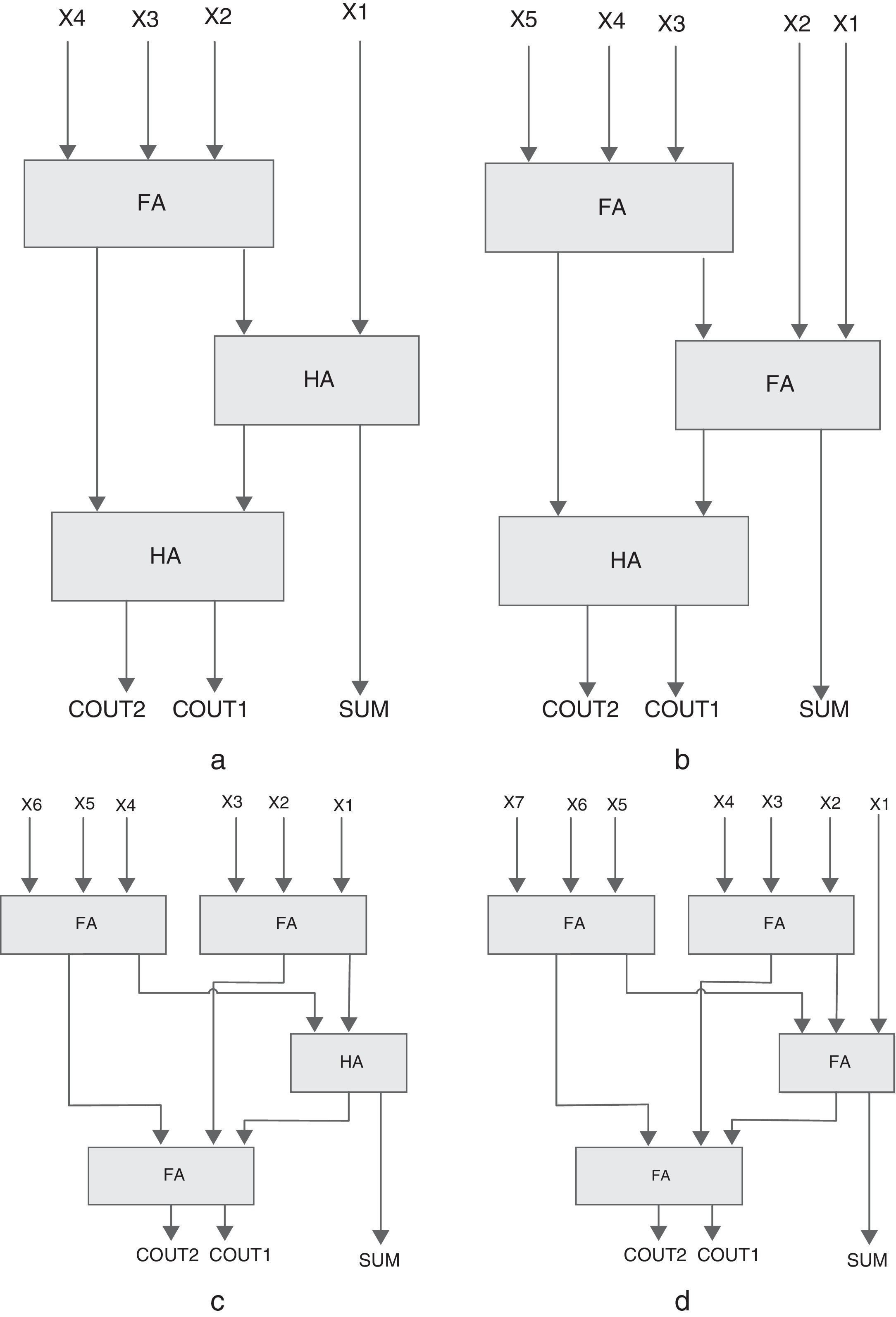
A 4-to-3 counter is a network with 4 inputs and 3 outputs, where the outputs show the count the 1's inputs. As shown in Fig. 2(a), a 4-to-3 counter is contained of a full adder and two half adders in series. Another structure for 4-to-3 counter has been designed in Mehrabi, Mirzaee, Zamanzadeh, et al. (2013) (Fig. 3). The actual efficiency of these counter cells extremely depends on the underlying technology which hosts the implementation of the primary blocks (i.e., MUX, XOR, and FA). Based on the CMOS implementation of these primary blocks, a total of 80 transistors are required for the 4-to-3 counter design of Fig. 3.
 4-to-3, (b) 5-to-3, (c) 6-to-3, and (d) 7-to-3 counter.")
, Mehrabi, Navi, et al. (2013); Mehrabi, Mirzaee, Moaiyeri, et al. (2013).")
The 4-to-3 counter in Mehrabi, Mirzaee, Zamanzadeh, et al. (2013), Mehrabi, Navi, et al. (2013); Mehrabi, Mirzaee, Moaiyeri, et al. (2013).
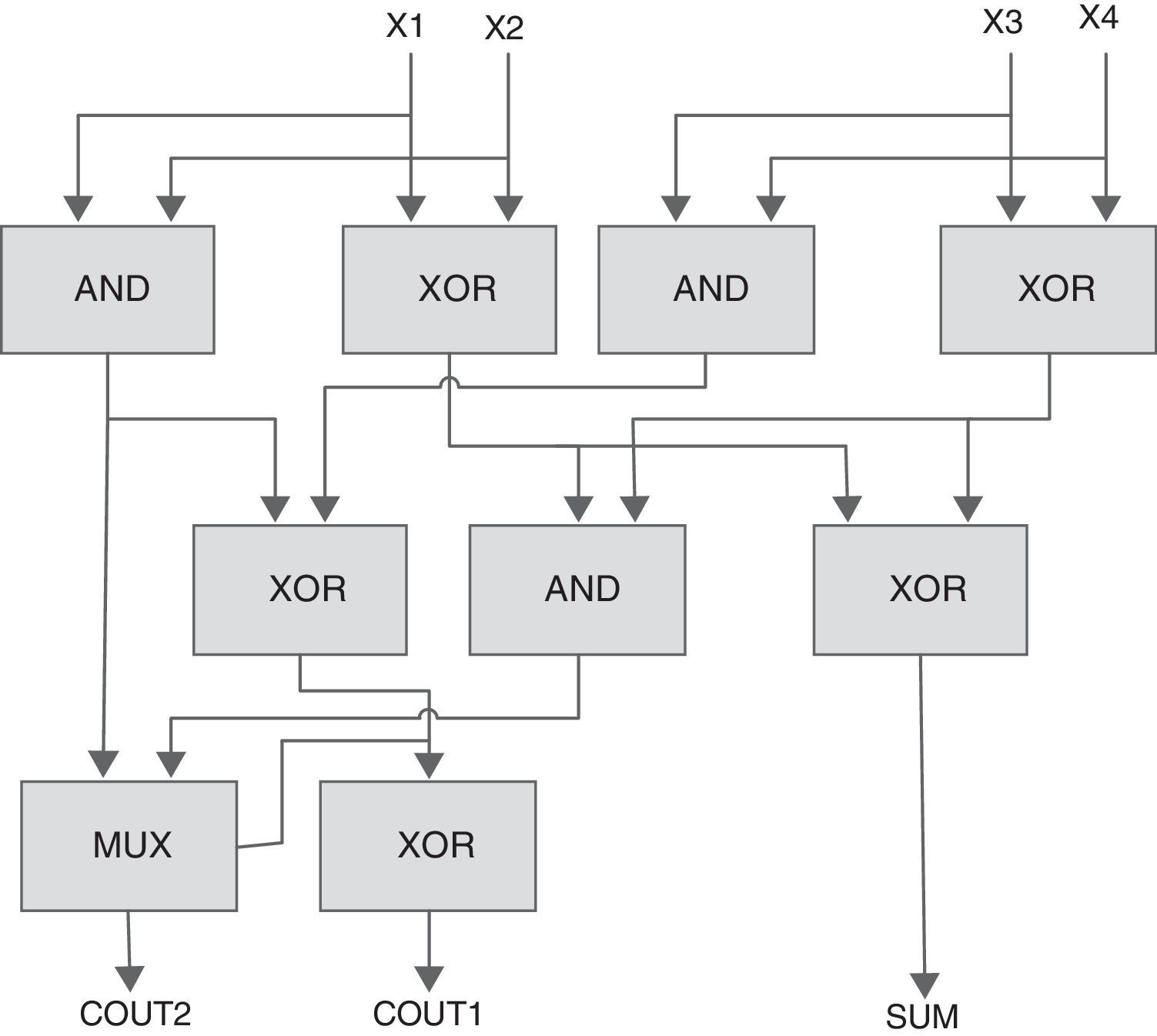
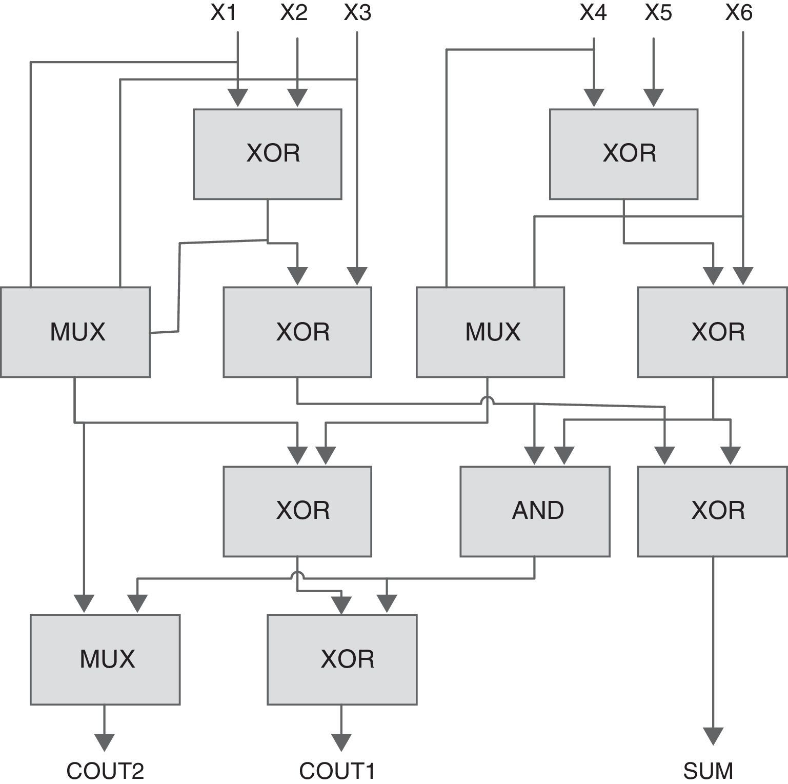
A 5-to-3 counter will compress five partial products into three outputs. As shown in Fig. 2(b), this counter is constructed using two full adders and one half adder in series. The counting limit of this counter is zero to five. The conventional 5-to-3 counter actually has five XOR gates to generate the output. Because of its importance, researchers have proposed different methods by rearranging the XOR gates to reduce the delay in this counter. A 5-to-3 counter has been designed in Chowdhury, Banerjee, Roy, and Saha (2008a, 2008b) (Fig. 4). It is a hybrid structure of 2-input XORs, MUXs, and a 2-input AND gate. In comparison with its conventional 5-to-3 counter, it benefits from a shorter critical path. A total of 80 transistors are required to design this cell using a CMOS implementation of basic blocks.
.")
The 5-to-3 counter in Chowdhury et al. (2008a, 2008b).
A 6-to-3 counter compress six partial products into three outputs. The structure of this counter is composed of three full adders and one half adder (Fig. 2(c)). This kind of counter could be used in a high speed multiplier to reduce the number of partial products. A 6-to-3 counter has been designed in Mehrabi, Mirzaee, Zamanzadeh, et al. (2013), Mehrabi, Navi, et al. (2013); Mehrabi, Mirzaee, Moaiyeri, et al. (2013). It is a hybrid structure of 2-input XORs, MUXs, and a 2-input AND gate. A total of 112 transistors are required to design the cell in Fig. 5, using a CMOS implementation of basic blocks.
, Mehrabi, Navi, et al. (2013); Mehrabi, Mirzaee, Moaiyeri, et al. (2013).")
The 6-to-3 counter in Mehrabi, Mirzaee, Zamanzadeh, et al. (2013), Mehrabi, Navi, et al. (2013); Mehrabi, Mirzaee, Moaiyeri, et al. (2013).
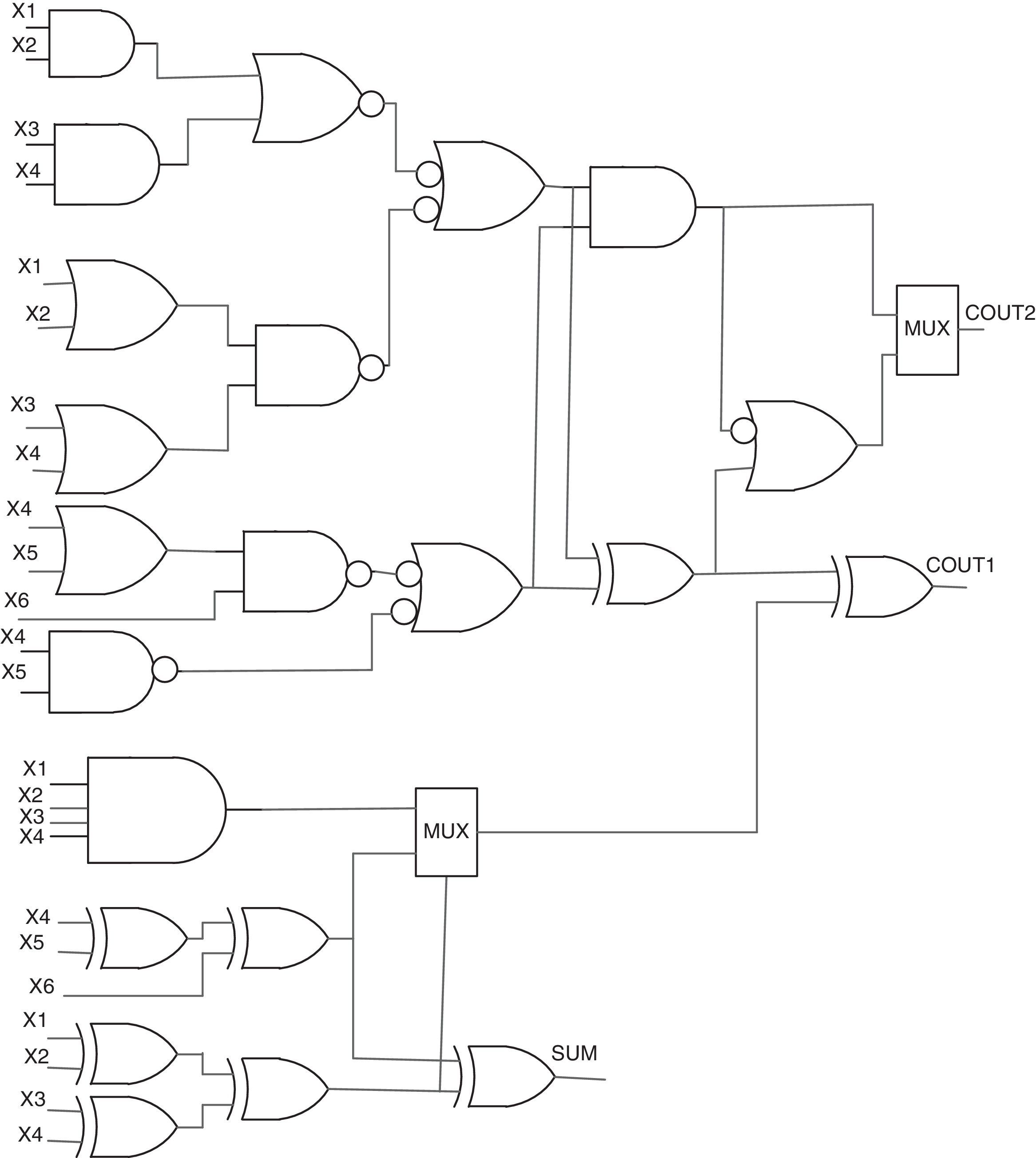
A 7-to-3 counter includes seven inputs and three outputs called SUM, COUT1 and COUT2. The architecture of a conventional 7-to-3 counter is shown in Fig. 2(d). This counter is composed of four full adders. In Ghasemzadeh, Mohabbatian, Akbari, Hadidi, and Khoei (2014), a novel CMOS structure for the 7-to-3 counter is designed. In this design, the outputs are based on the number of bits with value ‘1’ in truth table. Another design for the 7-to-3 counter has been proposed in Mohd et al. (2013) (Fig. 6). The actual performance of these counter cells heavily depends on the underlined technology as well, that hosts the implementation of the basic blocks (i.e., FA, XOR and MUX). Based on the CMOS implementation of these basic blocks, a total of 180 transistors are required for the 7-to-3 counter design of Fig. 6.
.")
The 7-to-3 counter in Mohd et al. (2013).
In addition, in Dandapat, Ghosal, Sarkar, and Mukhopadhyay (2010) different counter logics are designed upon the concept of the counter of a full adder. It could be defined as a single-bit adder circuit, which has four/five/six/seven inputs and three outputs. In Joshy, Prasath, Ravi, and Karman (2012), different CNFET counter cells using full adder cells are designed. However, the design of counter cells including full adder trees has a relatively high delay and consumes more power. These counter structures also grow quickly with the input vector size in terms of the needed number of full adder cells.
In Mehrabi, Navi, et al. (2013) two different structures of low power and high speed 6-to-3 and 7-to-3 compressors are proposed. Counter cells in this paper include XOR/MUX-based of full adder cells and a XOR/MUX-based structure.
4Proposed designs for counter cellsIn this section, four designs of 4-to-3, 5-to-3, 6-to-3 and 7-to-3 counters are proposed. These are composed of a capacitor network and a transistor network. In these designs, CNFETs with different threshold voltages are used to determine the required switching thresholds. According to Eq. (3), the diameter of the nanotubes controls the threshold voltage of the CNFET, which is used in different circuit designs. In the remainder of this section, a design proposal for different counter cells is presented. To design this counter, proper transistors with different threshold voltages (low, normal, and high) and appropriate NOT gates containing an NMOS with Vt=vt and a PMOS with |Vtp|=Vdd−vt are used. In the simulation by changing n1 and n2 according to Eq. (2), appropriate DCNT is reached. Therefore, based on Eq. (3), appropriate Vth is reached.
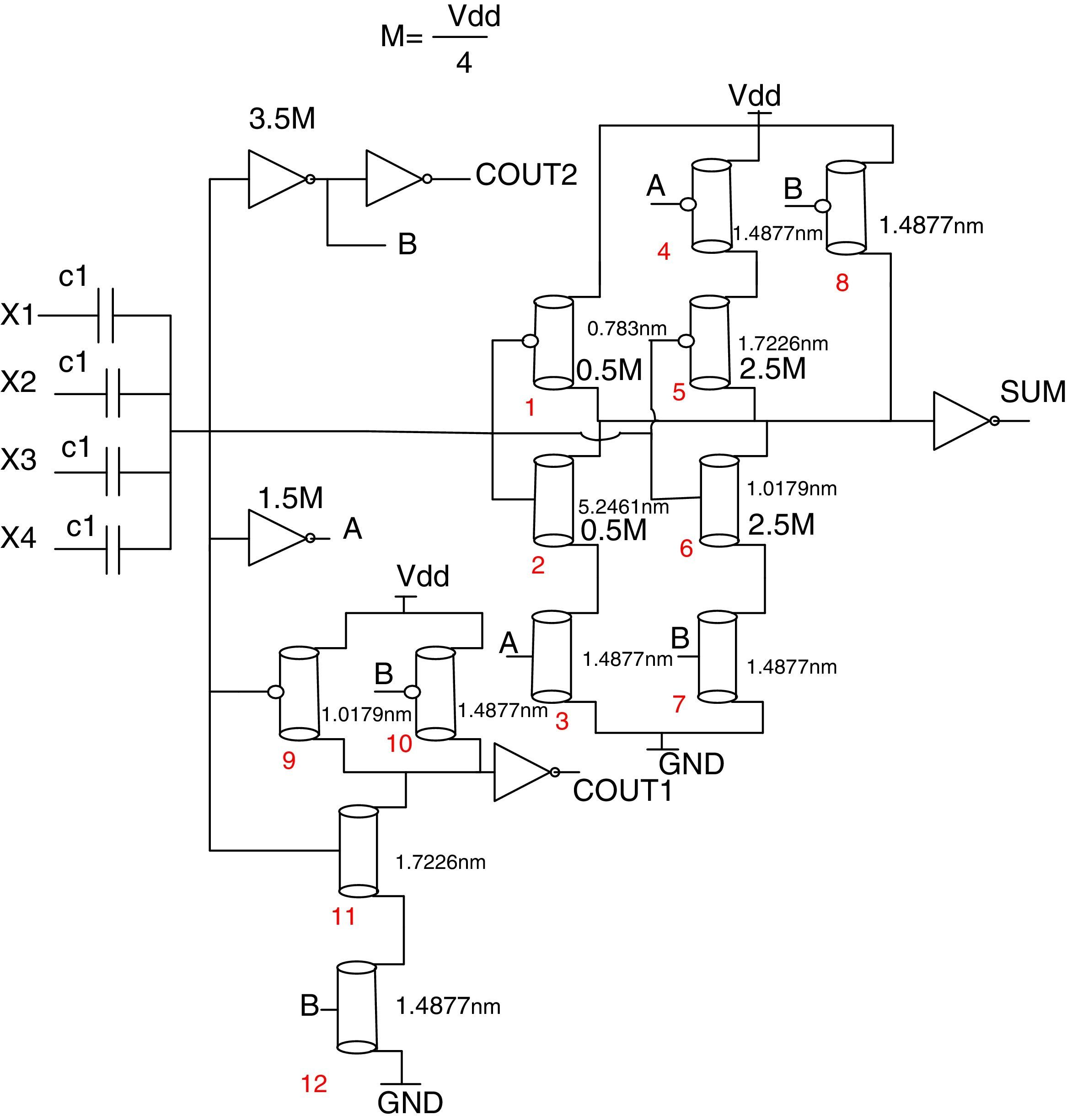
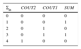
4.1Proposed 4-to-3 counterThe proposed 4-to-3 counter is designed based on the simplified truth table in Table 1. This circuit includes a single array of capacitors and a CNFET-based threshold detector network. As indicated in Table 1, the SUM output is ‘1’, if the sum of four inputs is equal to 1 or 3; otherwise, it is equal to ‘0’. COUT1 is equal to ‘1’, if sum of four inputs is equal to 2 or 3. The COUT2 is ‘1’ only when the sum of the four inputs is equal to 4.
Fig. 7 shows the details of this design for SUM, COUT1, and COUT2. To design this counter, proper transistors with different threshold voltages (low, normal, and high) and appropriate NOT gates containing an NMOS with Vt=vt and a PMOS with |Vtp|=Vdd−vt are used. In this design, a NOT gate containing an NMOS transistor with Vt=3.5M and a PMOS with |Vtp|=Vdd−3.5M is used, where ‘M’ is equal to Vdd/4. When the sum of the inputs is “four”, then the output of this NOT is “0”; otherwise, it is “1”. Another NOT gate which is used in this design contains an NMOS transistor with Vt=1.5M and a PMOS with |Vtp|=Vdd−1.5M. When the sum of the inputs is “zero” or “one”, then the output of this NOT is “1”; otherwise it is “0”. When the sum of the inputs is “zero”, the NMOS pull down transistor with low threshold of Vt=0.5M=0.1125 volts is “off”; otherwise, it is “on”. In this state, the PMOS pull up transistor with |Vtp|=0.5M is “on”; otherwise it is “off”. Both a PMOS and an NMOS with |Vt|=2.5M are used in this counter. When the sum of the inputs is “three” or “four”, then these transistors are “off” and “on”, and in the other states they are “on” and “off”, respectively. Other transistors have normal thresholds (Vt=Vdd/2).

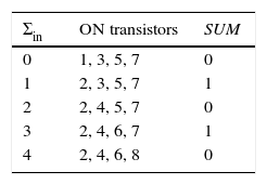
The same analysis can be done for the other two COUT1 outputs. The COUT2 output can be implemented only with two NOT gates. Table 2 shows the state of all transistors for different values of the sum of the inputs. Using this technique, a standard and symmetric circuit is obtained.
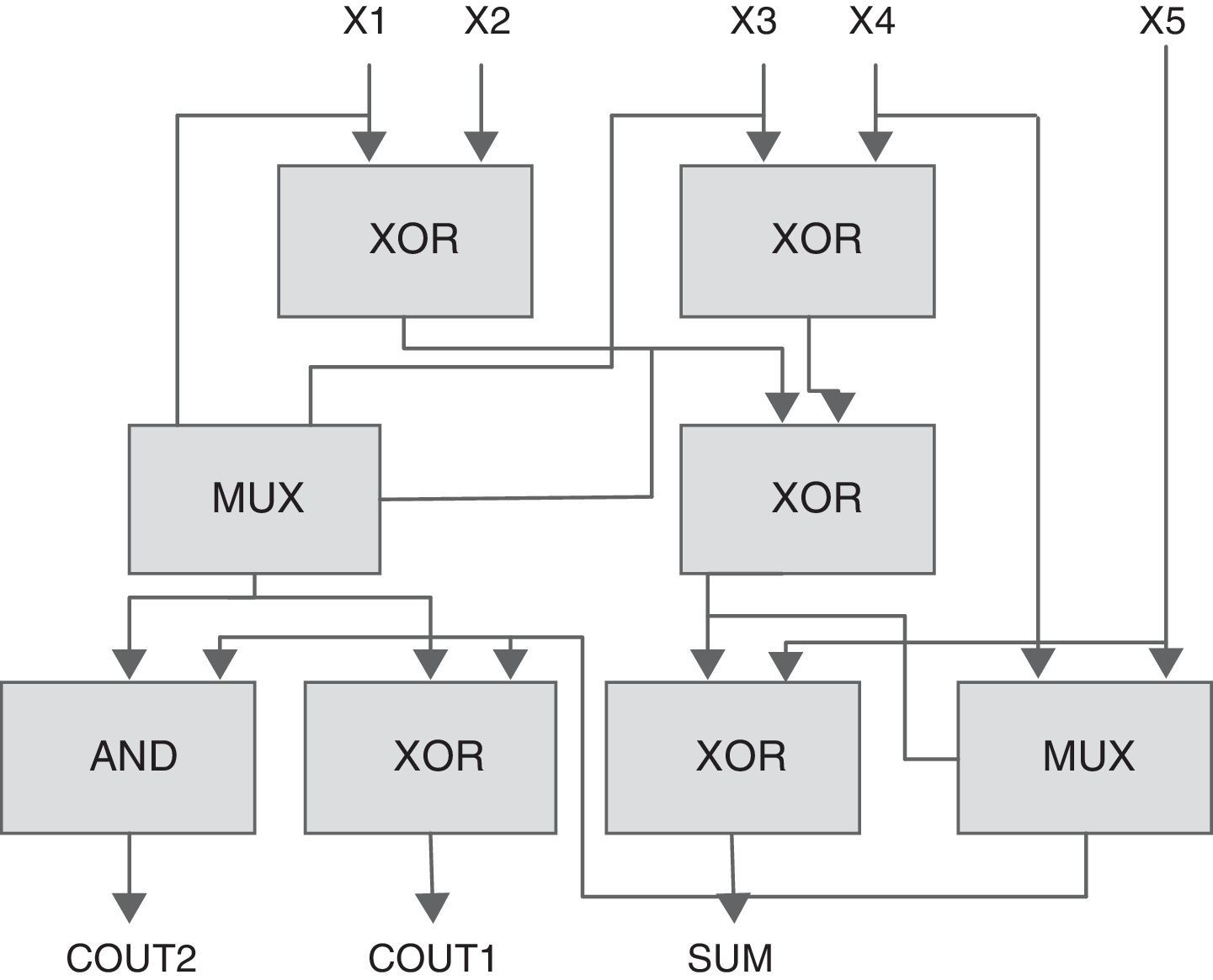
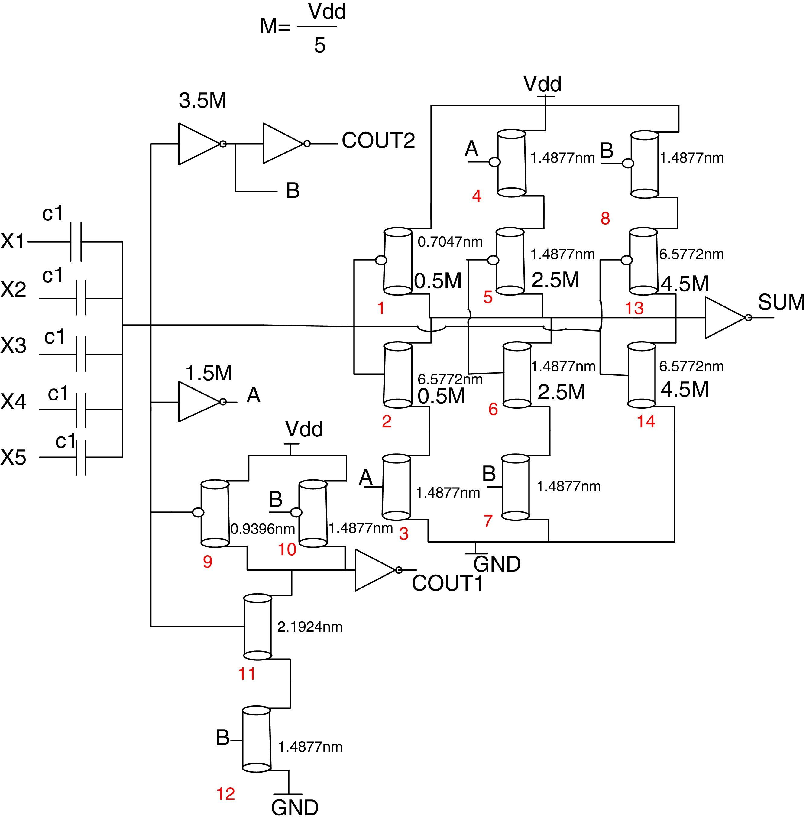
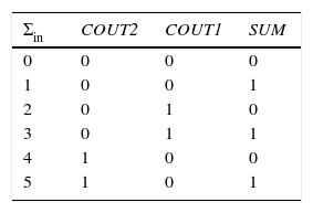
4.2Proposed 5-to-3 counterA 5-to-3 compressor has 5 inputs, X1, X2, X3, X4, X5 and three outputs, SUM, COUT1, and COUT2. A simplified truth table of this circuit is shown in Table 3. This truth table is similar to Table 1, but the one row for the sum of inputs equals 5. Therefore, the circuit for COUT1 and COUT2 remains unchanged, with respect to the 4-to-3 compressor, and only the circuit for the SUM needs a slight modification. However, the threshold voltage of all the transistors are changed because M=Vdd/5. Fig. 8 shows a complete circuit for the 5-to-3 counter proposed.

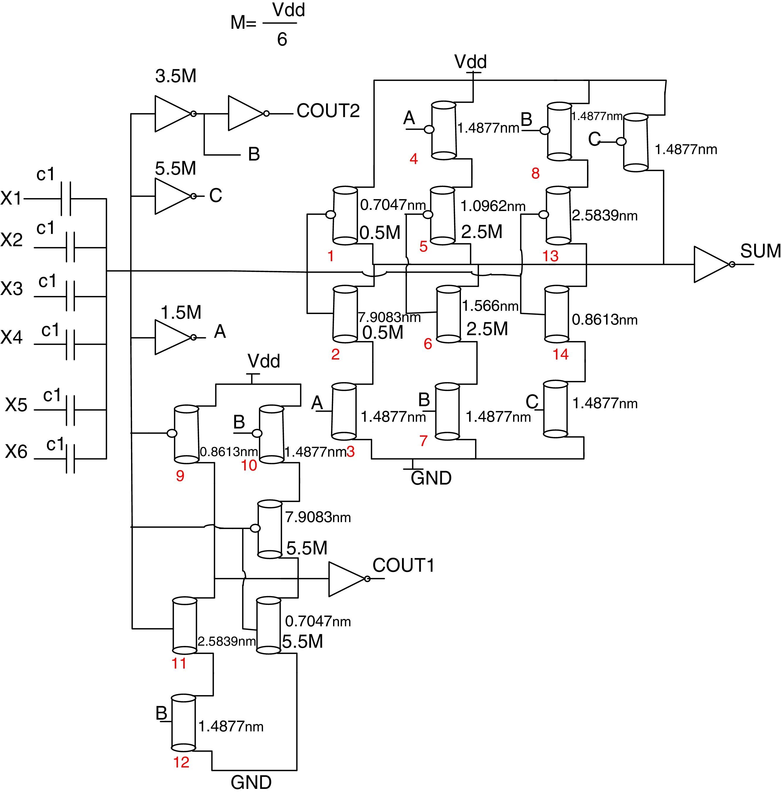
A 6-to-3 counter has 6 inputs, X1, X2, X3, X4, X5, X6 and three outputs, SUM, COUT1, and COUT2. The simplified truth table of this circuit is similar to Table 3, but the one row for the sum of inputs equals 6. As a result, the circuit for COUT2 remains unchanged, with respect to the 5-to-3 compressor and the circuit for the COUT1 and SUM needs slight modifications. The threshold voltages of all the transistors are changed because M=Vdd/6. Fig. 9 shows the complete circuit for the 6-to-3 counter proposed.
4.4Proposed 7-to-3 counter
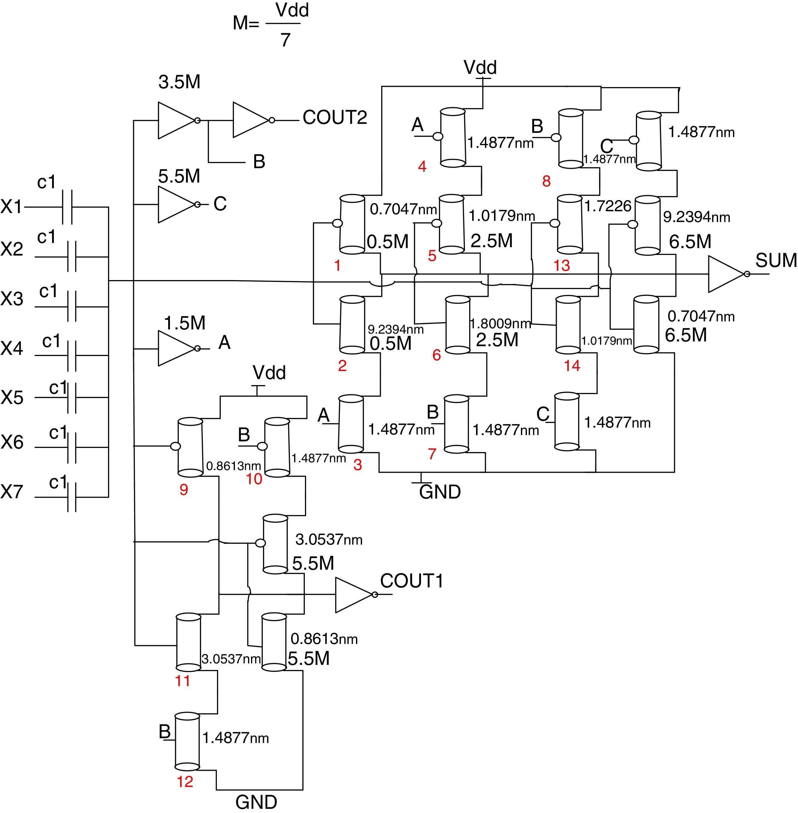
A 7-to-3 counter has 7 inputs, X1, X2, X3, X4, X5, X6, X7 and three outputs, SUM, COUT1, and COUT2. The simplified truth table of this circuit is similar to the simplified truth table of the 6-to-3 counter, but the one row for the sum of inputs equals 7. Hence, the circuit for COUT1 and COUT2 remains unchanged with respect to the 6-to-3 counter, and only the circuit for the SUM needs a slight change. The threshold voltages of all the transistors are changed because M=Vdd/7. Fig. 10 shows the complete circuit for the 7-to-3 counter proposed.
5Simulation results
All the designs proposed for the counters based on CNFET described in Section 4 are simulated using HSPICE. In these simulations, the compact model, presented in Deng and Wong (2007a, 2007b) is employed for the CNFET circuits. This standard model has been designed for unipolar and MOSFET-like CNFET devices. Each transistor in this model may consist of one or more CNTs. The 32nm PTM CMOS technology has been used for simulating CMOS circuits. These simulation results contain three common figures of merits: delay, power dissipation, and power-delay product (PDP). In all of these simulations, the room temperature is considered. Average power consumption during a long period of time is considered as the power consumption parameter. The delay is calculated from 50% voltage level of the input to 50% voltage level of the output. PDP is the multiplication of the average power consumption and the maximum delay. To measure the cell delay, all the possible transitions have been generated via test patterns and it is applied for all the structures.
The architectures proposed are compared to the best existing counter architectures in terms of power, delay, and PDP. For thorough evaluation of functionality of the designs in various conditions, simulations were performed at various supply voltages and room temperature, loads and frequencies. All the designs have been simulated at room temperature at 0.65, and 0.5 supply voltages, operating frequencies equal to 100MHz and 250MHz, and different load capacitances.
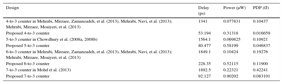
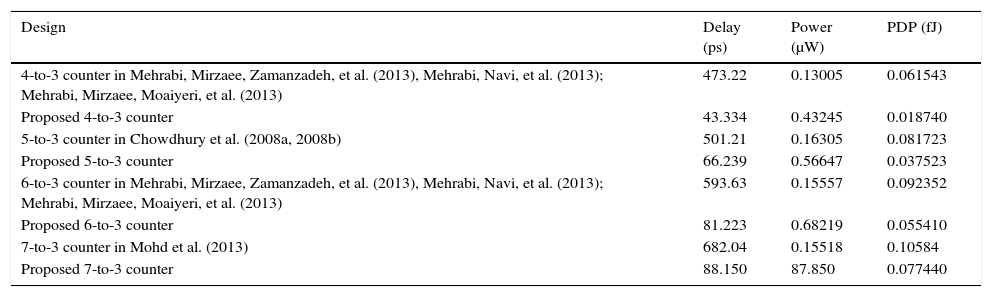
For comparisons, the best previous works on different counter cells were selected (Chowdhury et al., 2008a, 2008b; Mohd et al., 2013). First, the circuits are simulated at 0.65V and 0.5V supply voltages and at 250MHz operating frequency with 2.1fF output load capacitance. The results of this simulation are revealed in Tables 4 and 5, respectively. According to the experimental results, designs proposed have the lowest delay and PDP compared to the other designs at all supply voltages.
Simulation results for counters @ 250MHz with 2.1fF load in 0.65V.
| Design | Delay (ps) | Power (μW) | PDP (fJ) |
|---|---|---|---|
| 4-to-3 counter in Mehrabi, Mirzaee, Zamanzadeh, et al. (2013), Mehrabi, Navi, et al. (2013); Mehrabi, Mirzaee, Moaiyeri, et al. (2013) | 1341 | 0.077831 | 0.10437 |
| Proposed 4-to-3 counter | 53.194 | 0.31318 | 0.016659 |
| 5-to-3 counter in Chowdhury et al. (2008a, 2008b) | 1564.1 | 0.069825 | 0.10921 |
| Proposed 5-to-3 counter | 80.477 | 0.58199 | 0.046837 |
| 6-to-3 counter in Mehrabi, Mirzaee, Zamanzadeh, et al. (2013), Mehrabi, Navi, et al. (2013); Mehrabi, Mirzaee, Moaiyeri, et al. (2013) | 1849.1 | 0.10424 | 0.19276 |
| Proposed 6-to-3 counter | 228.35 | 0.52115 | 0.11900 |
| 7-to-3 counter in Mohd et al. (2013) | 1892.5 | 0.22321 | 0.42241 |
| Proposed 7-to-3 counter | 92.127 | 0.90202 | 0.083101 |
Simulation results for counters @ 250MHz with 2.1fF load in 0.5V.
| Design | Delay (ps) | Power (μW) | PDP (fJ) |
|---|---|---|---|
| 4-to-3 counter in Mehrabi, Mirzaee, Zamanzadeh, et al. (2013), Mehrabi, Navi, et al. (2013); Mehrabi, Mirzaee, Moaiyeri, et al. (2013) | 473.22 | 0.13005 | 0.061543 |
| Proposed 4-to-3 counter | 43.334 | 0.43245 | 0.018740 |
| 5-to-3 counter in Chowdhury et al. (2008a, 2008b) | 501.21 | 0.16305 | 0.081723 |
| Proposed 5-to-3 counter | 66.239 | 0.56647 | 0.037523 |
| 6-to-3 counter in Mehrabi, Mirzaee, Zamanzadeh, et al. (2013), Mehrabi, Navi, et al. (2013); Mehrabi, Mirzaee, Moaiyeri, et al. (2013) | 593.63 | 0.15557 | 0.092352 |
| Proposed 6-to-3 counter | 81.223 | 0.68219 | 0.055410 |
| 7-to-3 counter in Mohd et al. (2013) | 682.04 | 0.15518 | 0.10584 |
| Proposed 7-to-3 counter | 88.150 | 87.850 | 0.077440 |
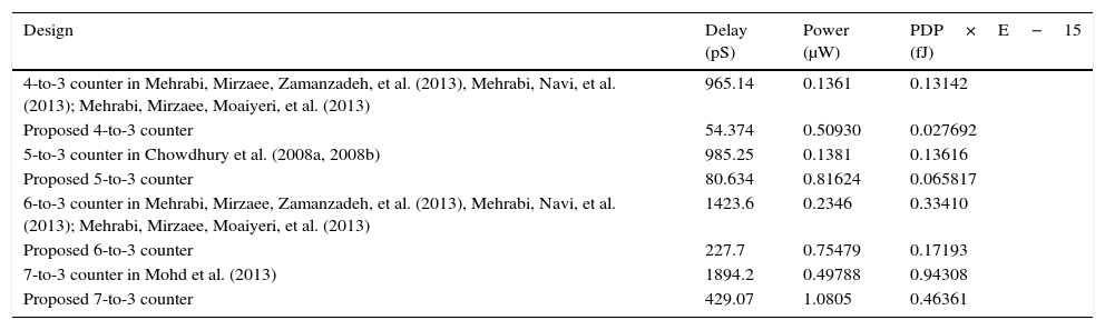
In the second experimentation, all the circuits were simulated at the discussed 0.65 supply voltage and 100MHz frequency using 2.1fF output capacitor. It is comprehended from Table 6. The designs proposed have the best PDP and power in comparison with the other circuits.
Simulation results for counters @ 1000MHz with 2.1fF load in 0.65V.
| Design | Delay (pS) | Power (μW) | PDP×E−15 (fJ) |
|---|---|---|---|
| 4-to-3 counter in Mehrabi, Mirzaee, Zamanzadeh, et al. (2013), Mehrabi, Navi, et al. (2013); Mehrabi, Mirzaee, Moaiyeri, et al. (2013) | 965.14 | 0.1361 | 0.13142 |
| Proposed 4-to-3 counter | 54.374 | 0.50930 | 0.027692 |
| 5-to-3 counter in Chowdhury et al. (2008a, 2008b) | 985.25 | 0.1381 | 0.13616 |
| Proposed 5-to-3 counter | 80.634 | 0.81624 | 0.065817 |
| 6-to-3 counter in Mehrabi, Mirzaee, Zamanzadeh, et al. (2013), Mehrabi, Navi, et al. (2013); Mehrabi, Mirzaee, Moaiyeri, et al. (2013) | 1423.6 | 0.2346 | 0.33410 |
| Proposed 6-to-3 counter | 227.7 | 0.75479 | 0.17193 |
| 7-to-3 counter in Mohd et al. (2013) | 1894.2 | 0.49788 | 0.94308 |
| Proposed 7-to-3 counter | 429.07 | 1.0805 | 0.46361 |
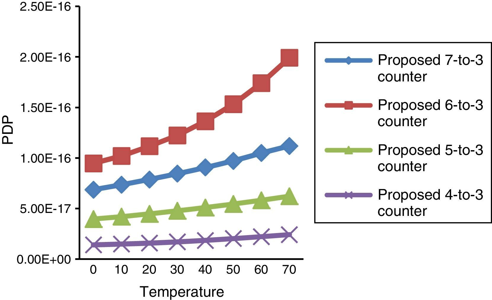
Another important feature of the circuits which should be considered is their immunity to ambient temperature variations. Thus, for investigating their sensitivity to temperature variation and noises, the circuits proposed were simulated in a vast range of temperatures, from 0°C up to 70°C at 0.65V supply voltage and 250MHz operating frequency with 2.1fF output load capacitance. The results are plotted in Fig. 11. This figure shows that the proposed design operates correctly with low energy consumption variation at different ambient temperatures.

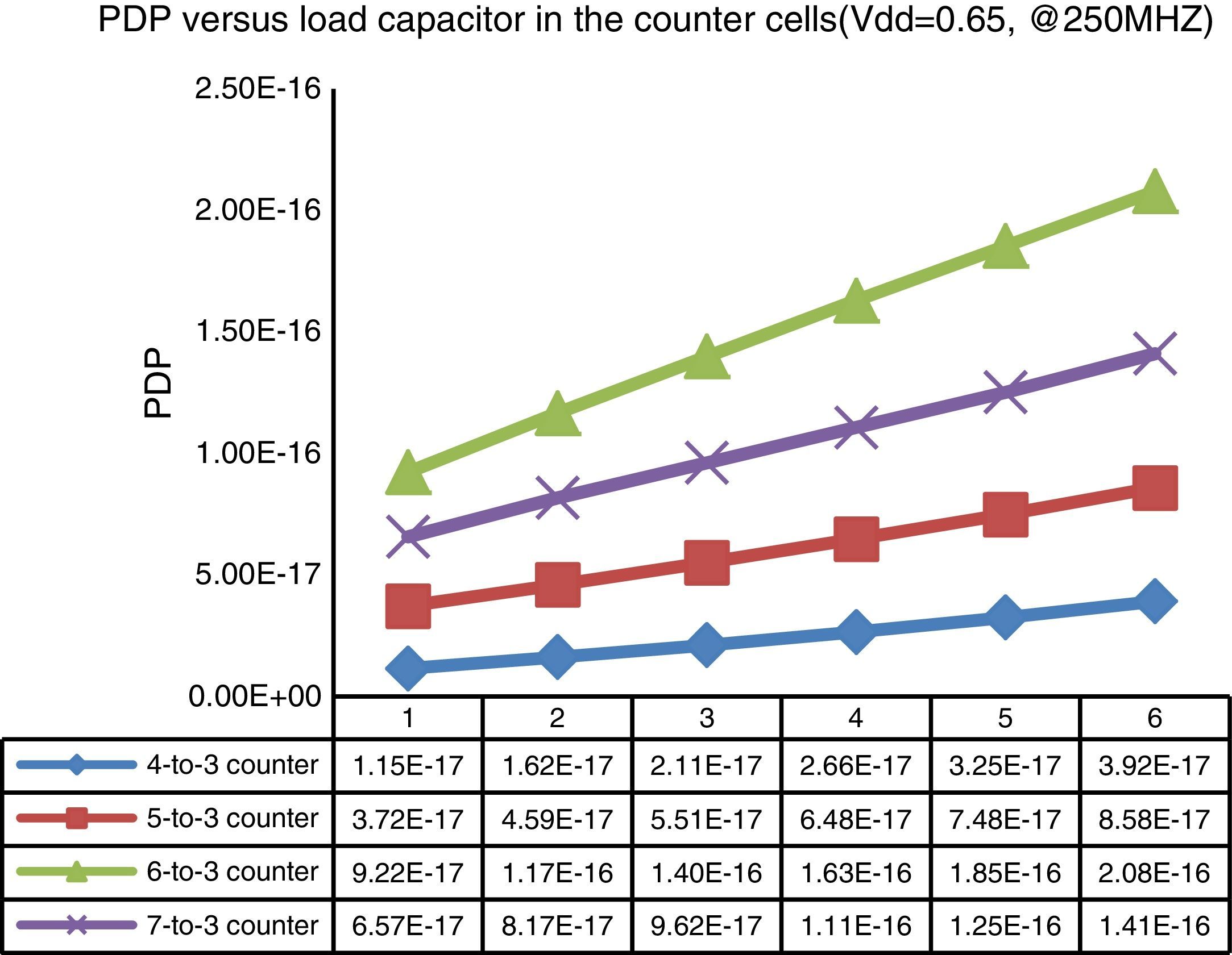
Driving capability is a very important metric for the logic gates. Thus, in this work the driving capability of the proposed structures is also scrutinized. The designs proposed are simulated using a variety of output load capacitors, ranging from 1 up to 6fF, at 0.65V supply voltage and 250MHz frequency. The PDP of the different counter designs, against the load capacitor variation, are schemed in Fig. 12.

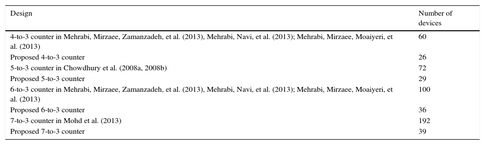
Table 7 indicates the number of elements used in different structures. As shown in this table, the designs proposed have a lower transistor in comparison to other designs.
The number of elements in different counter cells.
| Design | Number of devices |
|---|---|
| 4-to-3 counter in Mehrabi, Mirzaee, Zamanzadeh, et al. (2013), Mehrabi, Navi, et al. (2013); Mehrabi, Mirzaee, Moaiyeri, et al. (2013) | 60 |
| Proposed 4-to-3 counter | 26 |
| 5-to-3 counter in Chowdhury et al. (2008a, 2008b) | 72 |
| Proposed 5-to-3 counter | 29 |
| 6-to-3 counter in Mehrabi, Mirzaee, Zamanzadeh, et al. (2013), Mehrabi, Navi, et al. (2013); Mehrabi, Mirzaee, Moaiyeri, et al. (2013) | 100 |
| Proposed 6-to-3 counter | 36 |
| 7-to-3 counter in Mohd et al. (2013) | 192 |
| Proposed 7-to-3 counter | 39 |
The carbon nanotube field-effect transistor (CNFET) is one of the new devices to design low power and high performance circuits. In a multiplication process, to accumulate partial products, compressor and counter cells are used. 3-to-2, 4-to-2, and 5-to-2 compressors do not have enough capability to design high-bit size multipliers. In this paper, four novel high speed and low power carbon nanotube counter cells were proposed. These counters were capable to add 4 or 5 or 6 or 7 bits per decade, and generate 3 outputs. CNFETs with different threshold voltages were used to design our proposed counters. The counters proposed were simulated using HSPICE. The simulation results contained three common figures of merits: delay, power dissipation, and power-delay product (PDP). The simulation results indicate that the designs proposed consume low power and work properly. Our proposed counters are more effective for high order multiplications.
Conflict of interestThe authors have no conflicts of interest to declare.
Peer Review under the responsibility of Universidad Nacional Autónoma de México.