


The increase in pollution, using photocatalytic materials to degrade organic pollutants remains in force. ZnO is the most used semiconductors for photocatalytic applications. The oriented growth of nanostructures on substrates or seed layers (SL) improves the physical and chemical properties compared to the bulk-grown material. In this work, the photocatalytic efficiency of ZnO nanorods and nanoflowers was evaluated, obtained by hydrothermal growth (HG) over SL deposited by the spin-coating technique (SCT). The characterizations results showed two types of growth: 1D nanostructures with a dimension in the range of 400–1000nm and diameters of 70–100nm, and 1D microstructures with approximate 5–11μm length and diameters of 1–2μm. However, in the 7 SL system, micro prisms were generated, which led to the formation of 3D nanostructures (micro flowers) of ZnO with a maximum of 6μm in diameter. The system with 1D and 3D ZnO nanostructures, grown in 7 SL, was the most efficient methylene blue degradation. Achieving 100% transformation in 120min, with a rate constant of 2.98×10⁻²min−1. The results show that the SCT deposit combined with the sol–gel method and HG produces 1D and 3D structures with high potential in photocatalytic degradation.
El aumento de la contaminación, el empleo de materiales fotocatalíticos para degradar contaminantes orgánicos continúa vigente. El óxido de zinc (ZnO) es el semiconductor más utilizado para aplicaciones fotocatalíticas. El crecimiento orientado de nanoestructuras sobre capas semillas (SL) mejora las propiedades físicas y químicas comparado con el material crecido en bulto. En este trabajo se evaluó la eficiencia fotocatalítica de nanovarillas y nanoflores de ZnO obtenidas por crecimiento hidrotérmico (HG) sobre SL depositadas por la técnica spin coating (SCT). Los resultados de las caracterizaciones mostraron dos tipos de crecimiento: nanoestructuras 1D con dimensiones en el rango de 400 a 1.000 nm y diámetros de 70 a 100 nm, y microestructuras 1D con longitud aproximada de 5 a 11 μm y diámetros de 1 a 2 μm. Sin embargo, en el sistema de 7 SL se generaron microprismas orientados, generando nanoestructuras 3D (microflores) con un diámetro máximo de 6 μm. Este sistema fue el más eficiente en la degradación de azul de metileno. Degradando de 100% en 120 min, con una constante de velocidad de 2,98 x 10⁻² min-1. Los resultados indican que la SCT combinada con el método sol-gel y el HG produce estructuras 1D y 3D con alto potencial de degradación fotocatalítica.

ZnO is used as a sunscreen and in solar cells due to its optoelectronic properties, making it a material of interest in research focused on solving water pollution problems. It has a forbidden band gap (≈3.2eV) that makes it photosensitive to UV radiation, which allows the mobility of charge carriers (e−/h+) on its surface, that produce redox reactions during the photocatalytic process [1]. In 1D nanostructures, the photocatalytic efficiency of ZnO is highly dependent on the polar planes, as they influence surface defects that affect adsorption and surface reactivity [2,3]. In the ZnO hexagonal wurtzite crystalline form, anisotropic crystal growth has been reported, with 1D nanostructures in the form of nanotubes, nanowires, nanofibers, and nanoneedles [4,5]. To obtain the 1D nanostructures, different methods have been used to deposit the SL, some of them are: pulsed laser deposition [6], spray pyrolysis [7], magnetron sputtering [8], electrodeposition and atomic layer deposition [9].
In relation to the use of ZnO 1D as a photocatalyst, the literature reports several studies in which this nanostructure has been synthesized from SL. In one of them SL were obtained from the atomic layer deposition method [10], to degrade methylene blue (MB). In this study, SL were deposited on silicon substrates with different thicknesses; they obtained long and dense nanorods arrays. In particular, the ZnO film with a thickness of 3nm promoted the growth of dense and c-axis oriented ZnO nanorods arrays, which improved the photocatalytic efficiency for MB dye degradation under UV light irradiation, achieving 70% transformation after 4h. In another study [11], the photocatalytic activity of ZnO nanorods was optimized. The nanorods were obtained by deposition of a ZnO SL using ultrasonic spray pyrolysis (USP) as the deposition technique, followed by HG. ZnO nanorods were used as a photocatalyst to degrade an aqueous methylene blue (MB) solution, using UV light as an irradiation source. They report that the higher photocatalytic efficiency (83%) is related to the orientation of the dominant face surface in the (002) plane of ZnO in its wurtzite crystalline form since the exposure of the (002) plane facilitates the adsorption of OH−, ions, so the reaction between the interstitial oxygen holes with OH− ions, increase the photocatalytic efficiency. In addition, the positive Zn-terminated faces (002) can easily adsorb the negatively charged MB molecules. In another research Bourfaa et al. obtained ZnO thin films with 200nm thickness, using the RF sputtering method; to be used as SL to grow 1D ZnO structures, using the HG. As a result of the growth, they obtained nanorods with shapes in nanoflowers when the films were placed horizontally to the solution at the HG stage. The results of the photocatalytic degradation of MB showed that the nanorods degraded more than 65%, while the nanoflowers degraded more than 80%. This demonstrated that ZnO nanoflowers have a high-efficiency photodegradation, attributed to the photogenerated carriers in the band gap of ZnO structure [12]. In this context, the aforementioned work demonstrates that the SL deposition technique influences the ZnO particle size, orientation, density, and variation of the size and shapes of grown nanostructures. All of which influence the mechanism and photocatalytic activity.
Regarding that with combined use of SCT for the deposition of ZnO SL and subsequent HG, is possible to obtain vertically aligned 1D ZnO structures, with high density and thickness in the range of micrometers to nanometers, and these nanoforms have been used in solar cells, gas sensors, biomedical applications, field effect transistors, among others [13,14]. However, its potential in photocatalysis has not been evaluated to date. Therefore, in this research work, the hydrothermal growth of 1D (nanorods) and 3D (microflowers) ZnO nanostructures was carried out from ZnO SL deposited in 3, 5 and 7 layers using SCT, for the photocatalytic degradation of MB.
Experimental detailsMaterials and reagentsFor the synthesis of ZnO, the reagents used were zinc acetate dihydrate (Zn (CH3COO)2·2H2O, 99%) and 2-propanol (C3H8O, 99.5%) from J.T. Baker. Monoethanolamine (C2H7NO, 99%), hexamethylenetetramine (C6H12N4, 99%), Meyer. Methylene blue (C16H18N3SCl·3H2O, 98.5%) from Civeq. All reagents are used as they come in their trademark.
Preparation of ZnO seed layersA precursor solution (0.28M) was obtained using the sol–gel method: first, 3.10g of zinc acetate dihydrate was dissolved in 2-propanol, this solution was constantly stirred for 15min. Then, 0.85mL of monoethanolamine was added drop by drop. The mixture thus prepared was heated to 60°C in a reflux system with constant stirring for 1h. After this, the solution was laid down for 72h at room temperature. Before the deposit of the ZnO films, glass substrates were washed for 10min with a 2:1 solution of H2SO4:H2O2. Finally, 100μL of the ZnO precursor solution (0.28M) was deposited on a 2.5cm2 glass substrate, using the SCT to a speed of 3000rpm for 30s in a spin coating equipment model WS-400BZ6NPP/LITE. Between each layer of ZnO deposited, a drying stage was carried out for 1h at 80°C to evaporate the solvent and the remaining organic residues. The procedure for depositing the layers was repeated 3, 5, and 7 times depending on the obtained system. Then, ZnO coatings were placed in a muffle and calcined for 1h at 500°C. The ZnO coatings obtained were identified as S1-3L, S2-5L, and S3-7L, where S corresponds to the system and L to the deposited coating layers.
Hydrothermal growth of ZnO nanostructuresFor the growth of the ZnO nanorods, an equimolar solution (0.01M) of zinc acetate dihydrate and hexamethylenetetramine was dissolved in distilled water and stirred for 30min. Then, in an autoclave reactor BAOSHISHAN of 100mL with Teflon container, the SL S1-3L added, S2-5L and S3-7L, and 25mL of the AcZnD/HMTA solution, was heated in an oven for 3h at 90°C. After this time, the hydrothermal reactor was allowed to cool to room temperature. Finally, the ZnO nanostructure was water-washed distilled and dried for 10min at 90°C. The ZnO nanostructures thus obtained were identified as HG-S1-3L, HG-S2-5L, and HG-S3-7L where HG corresponds to hydrothermal growth, S corresponds to the system and L to the number of layers of the coating.
Characterization of ZnO coatingsTo determine the crystalline structure of the ZnO coatings, an Empyrean model Malvern Panalytical X-ray diffractometer was used with Cu Kα1 radiation (1.5406Å), a step time of 0.404s and a scanning angle of 2θ between 20° and 70°. Diffraction peaks were identified using ICDD file 01-079-9878. The surface morphology of the ZnO nanostructures and the thickness of the cross-sectional surfaces of the ZnO coatings were examined by a Tescan model Mira 3 scanning electron microscope (SEM), coupled with energy dispersive spectroscopy (EDS) Bruker model XFlash 6160. Force microscopy atomic (AFM) was developed using Witec ALPHA 300 equipment. Diffuse reflectance spectra of the HG were recorded using a Varian Cary 100 UV–Vis spectrophotometer equipped with an integration sphere of diffuse reflectance for solids.
Evaluation of photocatalytic degradationThe photocatalytic activity of ZnO coatings (HG-S1-3L, HG-S2-5L, and HG-S3-7L) was evaluated in the degradation of 1mgL−1 of MB contaminant in an aqueous medium using λ=254nm UV light as activation source. Inside the Vidren brand photocatalytic reactor, was placed the dye solution, and six ZnO coatings (6.25cm2 area) with 3, 5, or 7 layers depending on the evaluated system. Prior to the start of irradiation to the photocatalytic system, the aqueous solution was continuously stirred in the dark for 30min to ensure the adsorption/desorption equilibrium of the dye molecules on the surface of the ZnO nanostructures. Afterwards, the photocatalytic system was irradiated with UV light for 240min, and took samples every 30min. The MB transformation evolution, was followed with a Shimadzu TOC-VSCH brand total organic carbon (TOC) analyzer and Eq. (1):
where TOC0 is the mineralization at time zero and TOCf is the final mineralization of each sample. The photodegradation reaction rate was calculated from the linear graph of ln(C0/C) against irradiation time (where C0 is the initial MB concentration, C is the MB concentration at time t).Results and discussionStructural analysis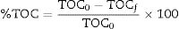
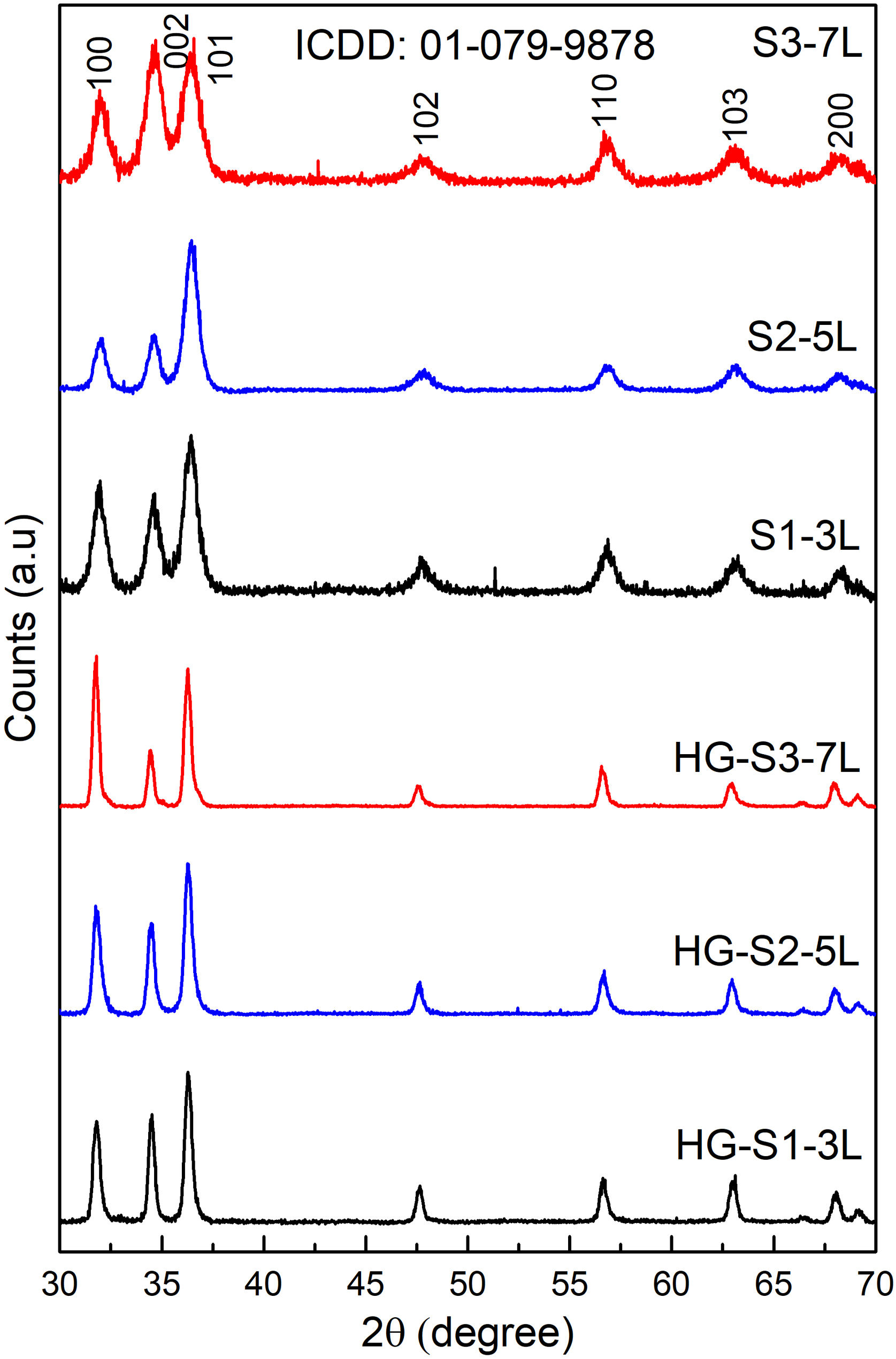
Fig. 1 shows the X-ray diffraction (XRD) the layer systems patterns seeds (S1-3L, S2-5L and S3-7L) and hydrothermal growth (HG-S1-3L, HG-S2-5L and HG-S3-7L). All samples exhibit diffraction peaks in the (100), (002), (101), (102), (110), (103), and (200) at 2θ=31.757°, 34.440°, 36.248°, 47.545°, 56.573°, 62.876° and 66.350° respectively, which correspond to the hexagonal wurtzite structure of ZnO according to ICDD 01-079-9878.
 and hydrothermal growth (HG-S1-3L, HG-S2-5L and HG-S3-7L).")
The quality of the orientation of the ZnO coatings was calculated using the diffractograms of Fig. 1 and the relative texture coefficient (Tc) [15]. This calculation is a related measure of the degree of preferential orientation shown by the material during growth in the hydrothermal stage, indicating the plane in which the material has a preference to grow under the conditions of synthesis of this work (2):
where TC(hkl) is the diffraction relating coefficient peaks corresponding to the interested plane. The term Ihkl0 is the standard diffraction intensity according to the ICDD crystallographic chart 01-079-9878, measurements from an oriented powder sample random. ΣN is the sum of the Bragg reflection number included in the analysis. Finally, Ihkl is the diffraction intensity measured from the plane of interest of the material characterized.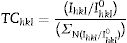
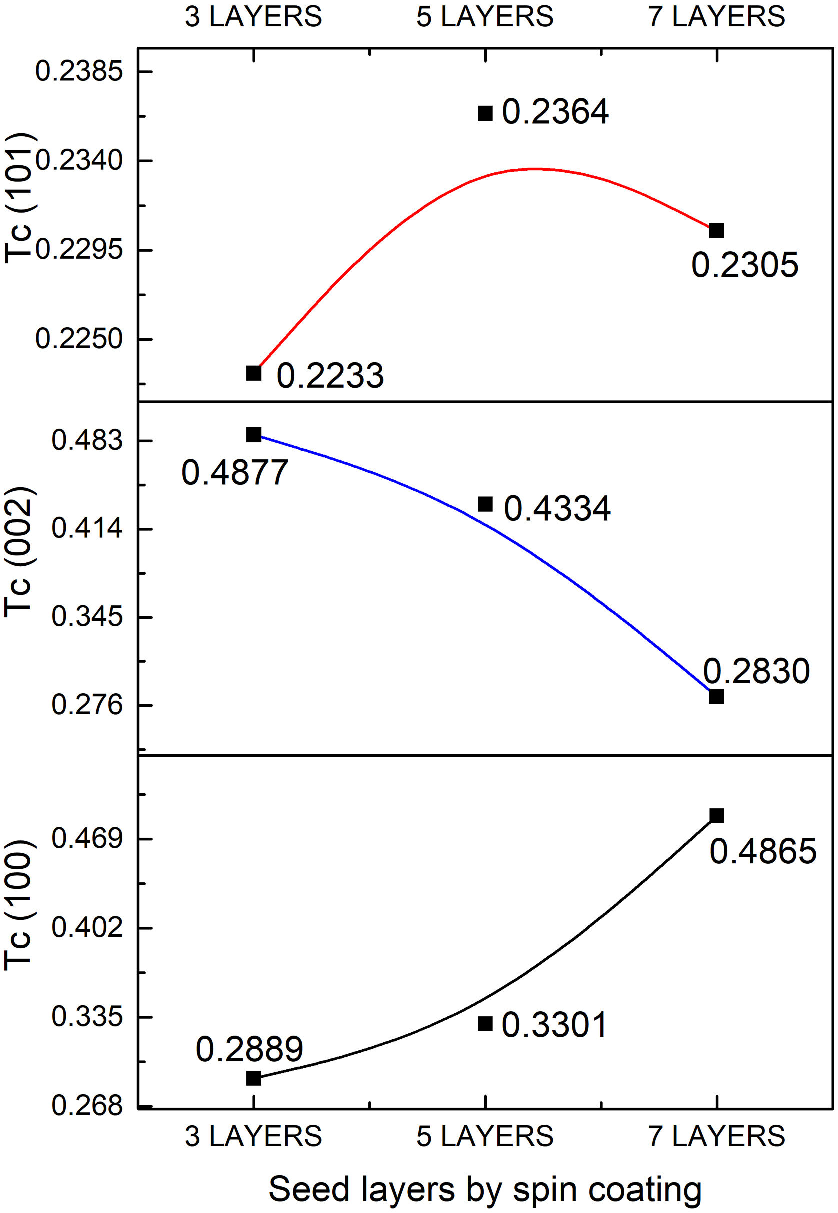
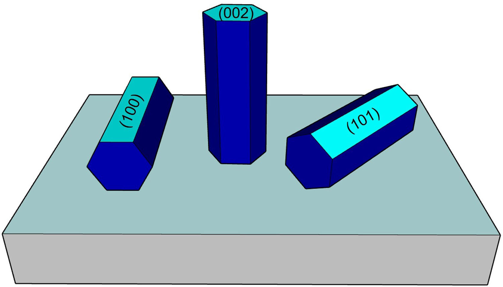
The calculated values of Tc of the planes (100), (002), and (101) of the coatings are shown in Fig. 2. It observed that the Tc values for the HG-S1-3L and HG-S2-5L overlays are larger in direction (002), so it concludes that nanostructures prefer to grow in this direction compared to other nanostructures planes, as seen in Fig. 3. In addition, we can also observe that for HG-S3-7L, the values of coefficient Tc, increased in the direction (100) and (101), but they reduce in address (002). This behavior in the value of Tc could correspond to the contribution of intensities in the signal due to the presence of flower-shaped structures [16].
Surface morphology of ZnO coatings

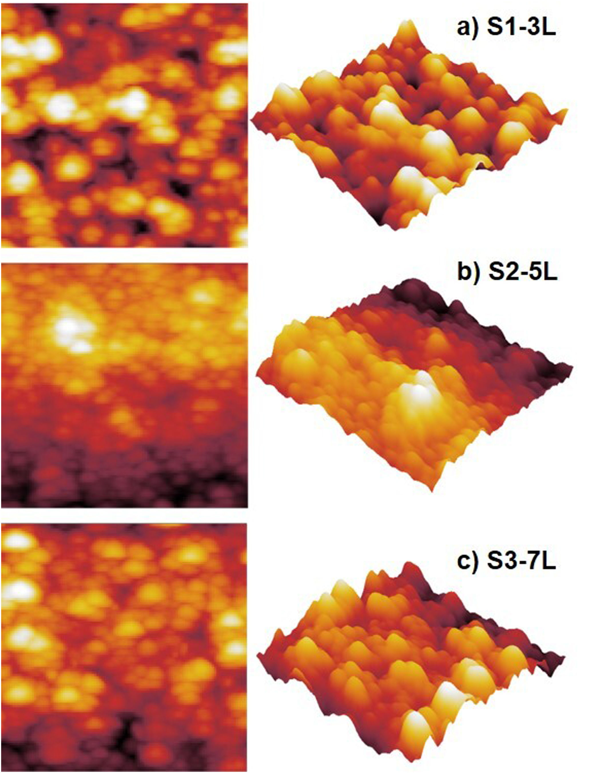
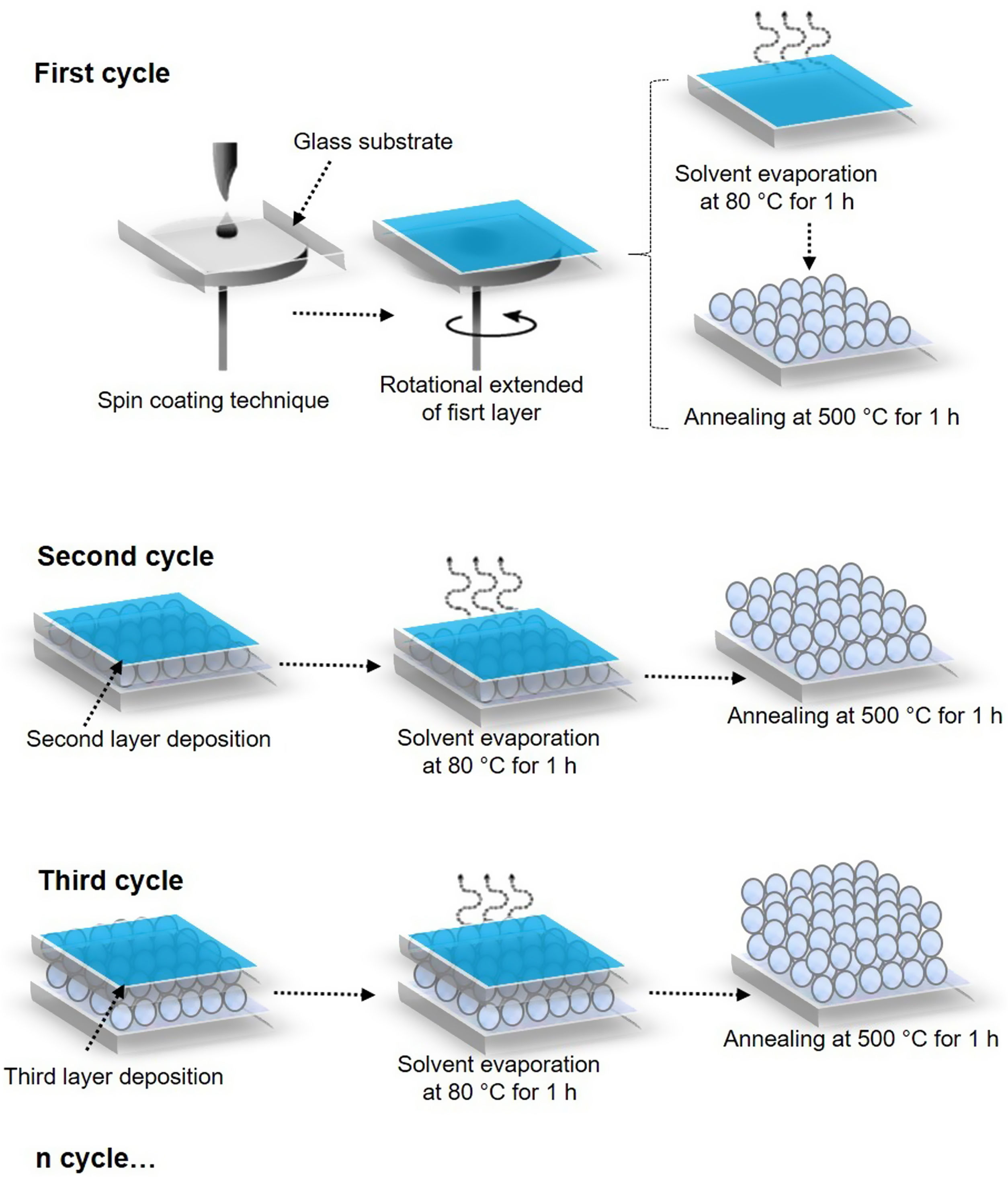
Fig. 4 shows the images of the superficial morphology of the samples in a scanned area of 1.0μm×1.0μm. It is known that the surface roughness of the ZnO coating can be affected by factors such as the shape of the nanostructures, the coating deposition conditions, the heat treatment of the samples, and the chemical reactions in the precursor solutions [17]. Due to the study variables in this work, we consider that the surface roughness of ZnO coatings is due to a coalescence effect in the structures due to spin coating process, and a mechanism of the interpenetration of new layers into the already deposited and heat treated ones [18]. Table 1 shows the roughness results from the root mean square (RMS). These results agree with the SEM micrographs of the ZnO SL. The cross-sectional surfaces of ZnO thickness SL were examined by SEM. Fig. 5 shows the process of deposition using the SCT followed by the heat treatment.
 S1-3L, (b) S2-5L and (c) S3-7L.")

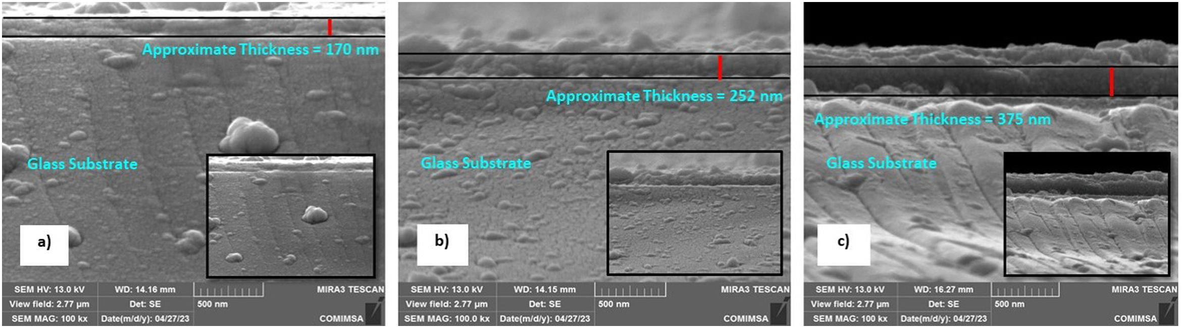
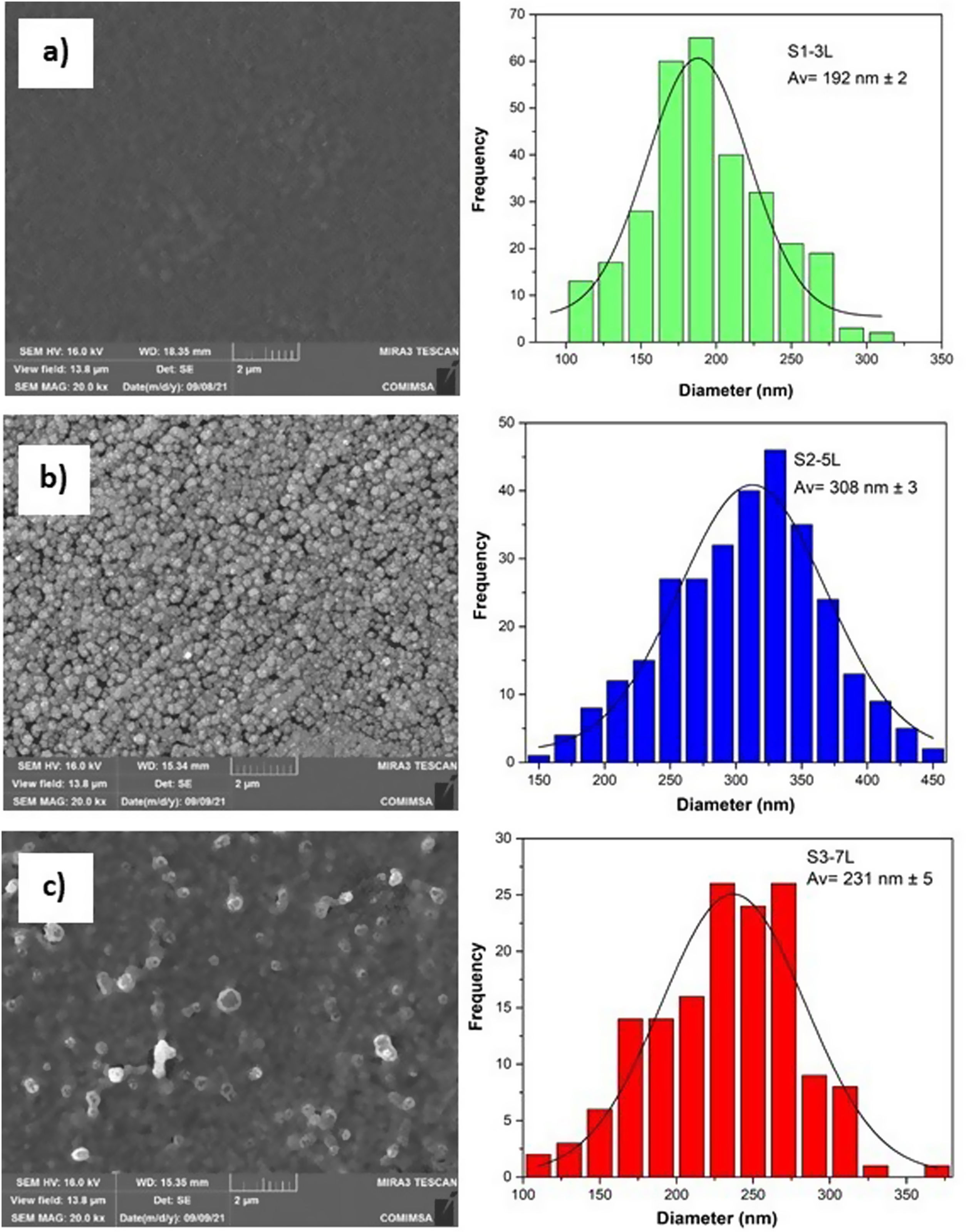
According to the profiles of the micrographs of Fig. 6, the thicknesses of the ZnO SL of samples S1-3L, S2-5L, and S3-7L measured by the cross-section they are 170±6nm, 252±30nm, and 375±13nm respectively. Many authors have mentioned that the increase in the thickness of the seed layer is related to the number of layers, that is, there is a correlation between the number of layers and the thickness [19–21]. Another factor that depends on the number of layers is the density of the seeds on the substrate [22–24]. Therefore, a greater thickness provides a greater growth area, which causes the increase in the diameter and density of ZnO nanorods. However, it has been reported that the length of the ZnO nanorods decreases as the thickness of the seed coat increases [25]. In this same sense, Fig. 7 shows the SEM micrographs of the ZnO coatings deposited by SCT. The surface morphology of the ZnO coatings of the three SL systems (S1-3L, S2-5L and S3-7L) corresponds to the micrographs in Fig. 7a–c. In them, homogeneous coatings with a spherical granular structure are observed whose grain size is 192±2nm, 308±3nm and 231±5nm for S1-3L, S2-5L and S3-7L, respectively. According to the upper and lower surface micrographs of Fig. 8a–c, for the three systems (HG-S1-3L, HG-S2-5L and HG-S3-7L) of hydrothermal growth (HG), the SL with a granular structure resulted in the formation of high-density ZnO nanowires, hexagonal in shape and nanometric sizes (Table 2). Reports show that the growth of 1D structures is due, as mentioned above, to thickness which in turn influences the density and granular structure of the ZnO SL, which are introduced as nucleation centers and as a controllable alignment agent of ZnO nanorods [26,27].
 S1-3L, (b) S2-5L and (c) S3-7L.")
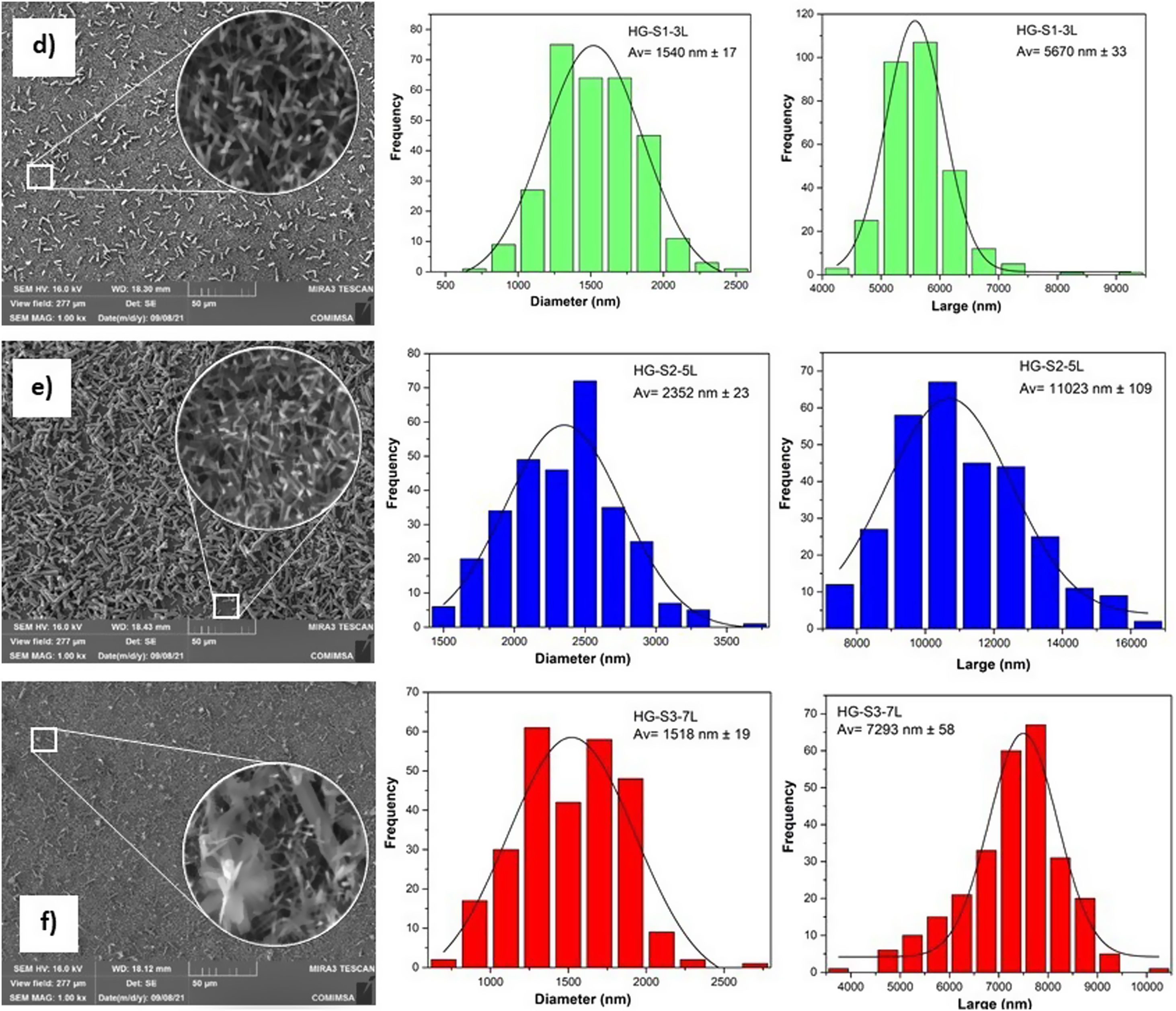
 S1-3L, (d) S2-5L and (c) S3-7L, n=300; view field: 13.8μm.")
 HG-S1-3L, (b) HG-S2-5L and (c) HG-S3-7L, n=300; view field: 277μm.")
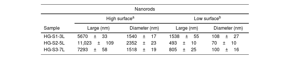
For the HG-S3-7L (8c) system, in addition to the growth of nanorods, 3D nanostructures in the form of ZnO microflowers up to 6μm in diameter, with petals 456nm wide and 3μm long, were also obtained. According to Fan et al., the growth process of ZnO nanoflowers is due to the precipitation of Zn(OH)2 produced by the combination of Zn2+ and OH− ions in the solution. Zn(OH)2 ions are formed when Zn(OH)42− is dissolved in water, so it is assumed that the ZnO nanoflowers developed due to an excess concentration of Zn(OH)42− ions [28], which, in our case, could have occurred by increasing the concentration of available ions when depositing 7 layers in the S3-7L system. Table 2 shows the average dimensions of the ZnO nanorods on the upper and lower surfaces. The dimensions obtained from the ZnO nanorods are approximate to the values reported (length: 3.000–900 nm; diameter 250–70nm) in other studies for their photocatalytic application [29,30], in which they used different deposition techniques than those used in this work.
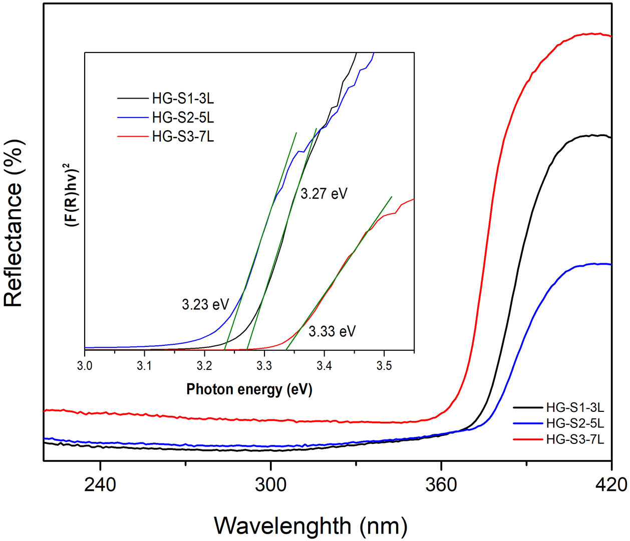
Calculation of the hydrothermal growth band gapZnO coatings with HG were characterized by UV–Vis diffuse reflectance spectroscopy (DRS) measurements made at room temperature in the 200–400nm wavelength range and presented in Fig. 9. It is observed that in UV light around 360–370nm, ZnO coatings are activated. For bandgap energy calculations, reflectance spectra were converted using the Kubelka–Munk (KM) function as an ideal model to relate reflectance and absorbance [31,32] according to Eq. (3).
where R is the reflectance. The use of the KM function makes it possible to obtain graphs analogous to Tauc [33,34], according to Eq. (4).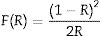
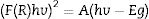

In the graph of (F(R)hv)2 versus photon energy (eV) inserted in Fig. 9, the value of the x-intercept corresponds to the bandgap energy of the coatings with HG. According to the band structure of a semiconductor, the band gap is the difference in energy between the conduction band and the valence band. The reported standard value of the ZnO band gap is 3.37eV [35]. In this investigation, the measured values of the band gap obtained are 3.27, 3.23, and 3.33eV, which indicates that they are similar to the values reported in the literature, and no significant changes in the band gap values are reported because our material is pure, in comparison with the values reported in investigations where ZnO is doped with different metals [36–38] or modifications are made in the ZnO synthesis parameters [39,40].
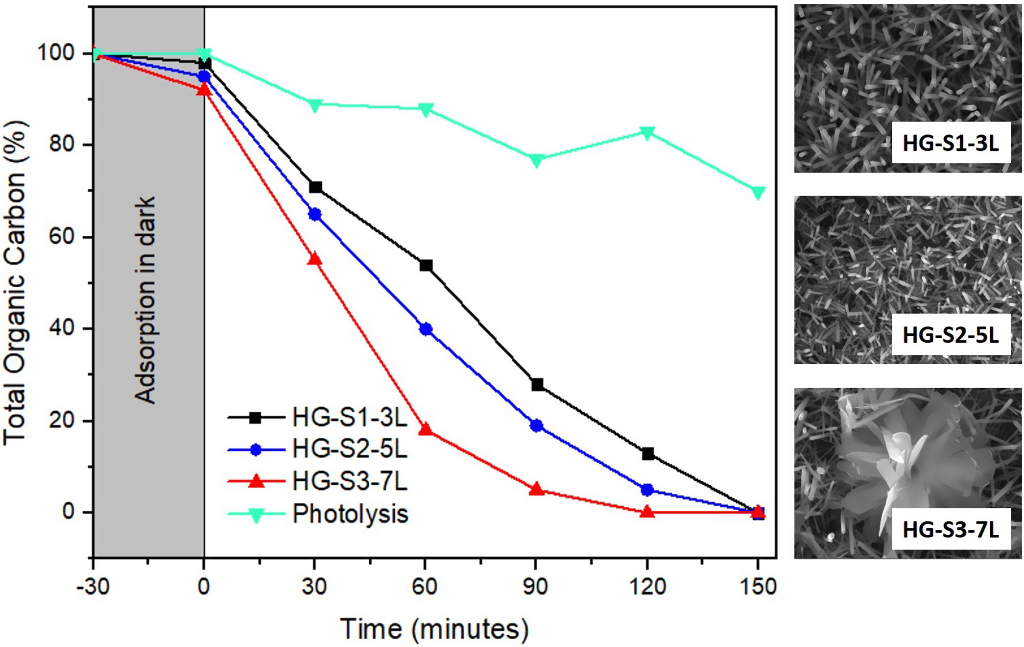
Photocatalytic evaluation of ZnO coatings with hydrothermal growthThe photocatalytic activity of the ZnO coatings (HG-S1-3L, HG-S2-5L, or HG-S3-7L), was evaluated for the degradation of 1mgL−1 of MB. Using only UV light as a source of activation of the ZnO nanostructures. The TOC analysis of the tests subjected to degradation with the film systems HG-S1-3L, HG-S2-5L, and HG-S3-7L, is shown in Fig. 10. It is observed that the amount of MB degraded during photolysis was 30%. However, with the photocatalytic treatment, it is observed that the best activity has been for HG-S3-7L, reaching a maximum of 100% MB mineralization with irradiation time of 120min and a rate constant of 2.98×10⁻²min−1. One of the factors that benefit the photocatalytic activity in one-dimensional nanostructures is the length of the nanorods. In them, the photoexcited electrons migrate along the axis of the nanostructure toward the tip of the nanorod, while the holes migrate to the sides, leading to an effective separation of the photogenerated charges [41] responsible for generating the OH that cause the mineralization of the MB. Considering the above, the density of the nanorods on the glass substrate results as another important factor that benefits the photocatalytic efficiency. In our case, according to Fig. 11 and the values in Table 3, the higher density of rods observed in the HG-S3-7L system resulted in a higher rate of dye mineralization. Studies have been done indicating that the polar face (002) promotes a better photocatalytic response because they are more active surfaces compared to the non-polar surfaces (100) and (101) perpendicular to them [42]. In addition to the above, it has been mentioned that nanoflowers provide a large surface area that allows a long charge transfer that can promote increased photocatalytic efficiency observed in ZnO with this type of 3D nanostructures compared to those with ZnO nanorods. Therefore, a higher density of 1D nanostructures and a long surface area provided by the 3D nanostructures (see Figs. 8 and 10) results in greater exposure of the polar face of the (002) plane and a long transfer of the photogenerated charges that cause a greater photocatalytic activity in HG-S3-7L.


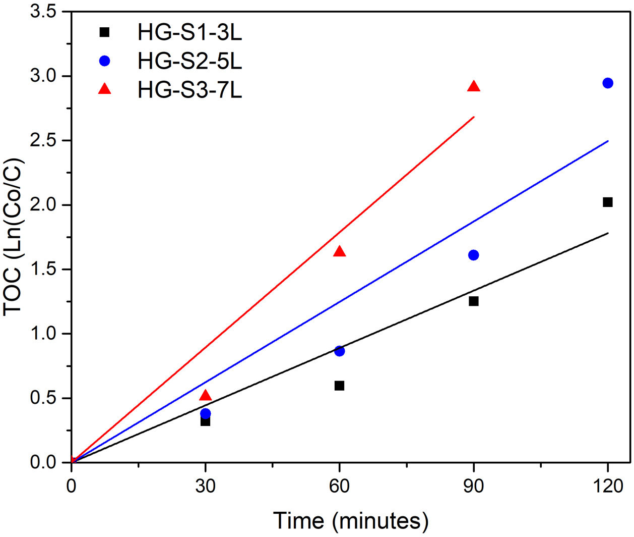
To know the kinetic parameters of the photocatalytic transformation process of MB, the rate constant (k) was calculated using the kinetic equation ln(C/C0)=k·t (see Table 3). The fit graphs of Fig. 11 indicate that the degradation reaction photocatalytic of MB is of the first order in all treatments.
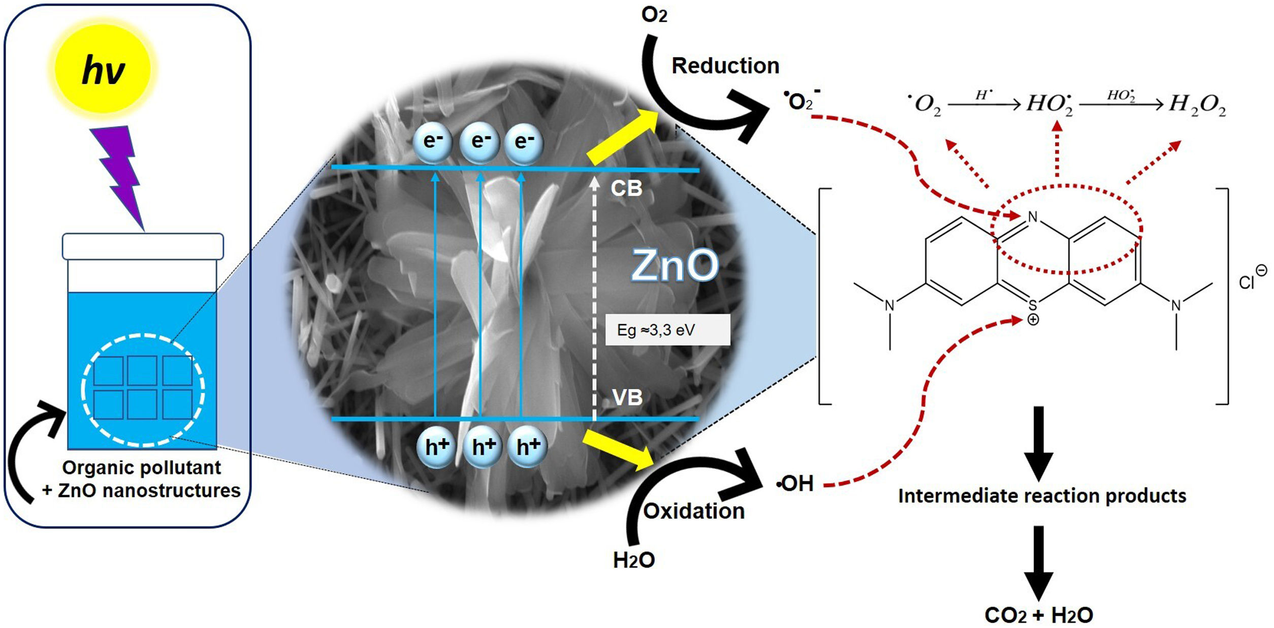
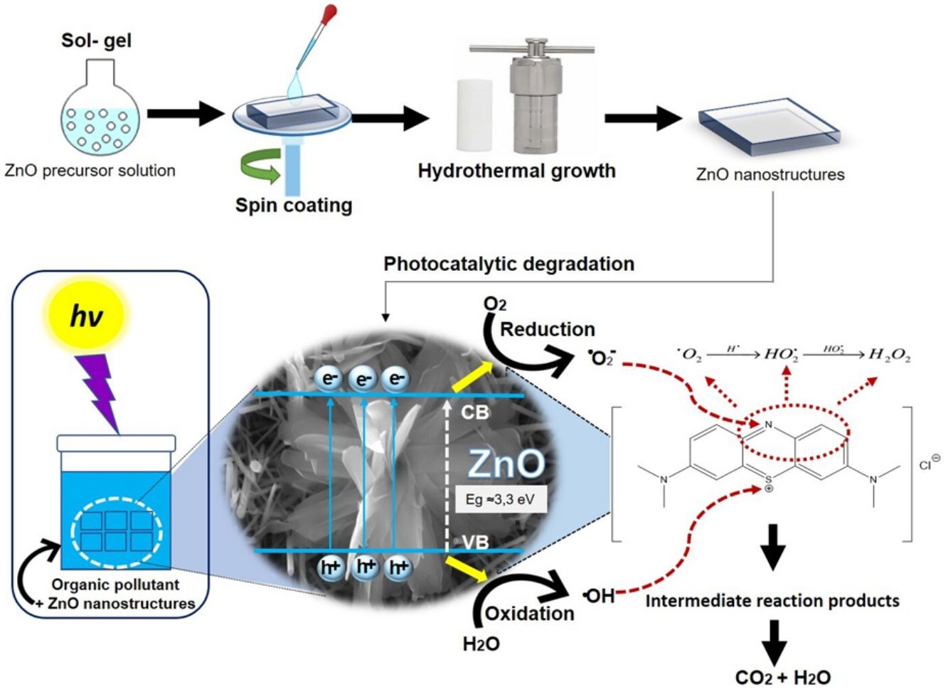
Fig. 12 shows the possible photocatalytic mechanism of this investigation. First, an absorption equilibrium is set from the liquid phase of the organic pollutant (MB) to the surface of the ZnO after the ZnO is irradiated with UV light with an energy of 4.48eV. This promotes the excitation of electrons from the valence band (BV) to the conduction band (BC) generating hole pairs of electrons (e−/h+). These species migrate to the ZnO surface and participate in oxidation and reduction reactions in the adsorbed phase. The holes generated (h+) in the valence band of ZnO react with the molecules of water and hydroxide ions to produce hydroxyl radicals. While electrons (e−) react with oxygen to produce superoxide radical anions and then peroxide hydrogen. The hydrogen peroxide will then react with the superoxide radicals to form hydroxyl radicals. These resulting hydroxyl radicals act as effective oxidants agents to transform the MB adsorbed on the ZnO surface into compound intermediaries so finally achieve the mineralization of transformation products [43].

As previously mentioned, there are no reports of using nanorods or nanoflowers obtained from ZnO SL deposited by the SCT for photocatalytic purposes. However, comparing the results of this research with those reported in the literature (see Table 4), it can be assumed that the ZnO films deposited by SCT followed by HG show higher photocatalytic activity in a reasonable time. This time difference in photocatalytic activity is likely by to the synergistic effect of 1D and 3D structures that takes place in the photocatalytic degradation system when using HG-S3-7L.
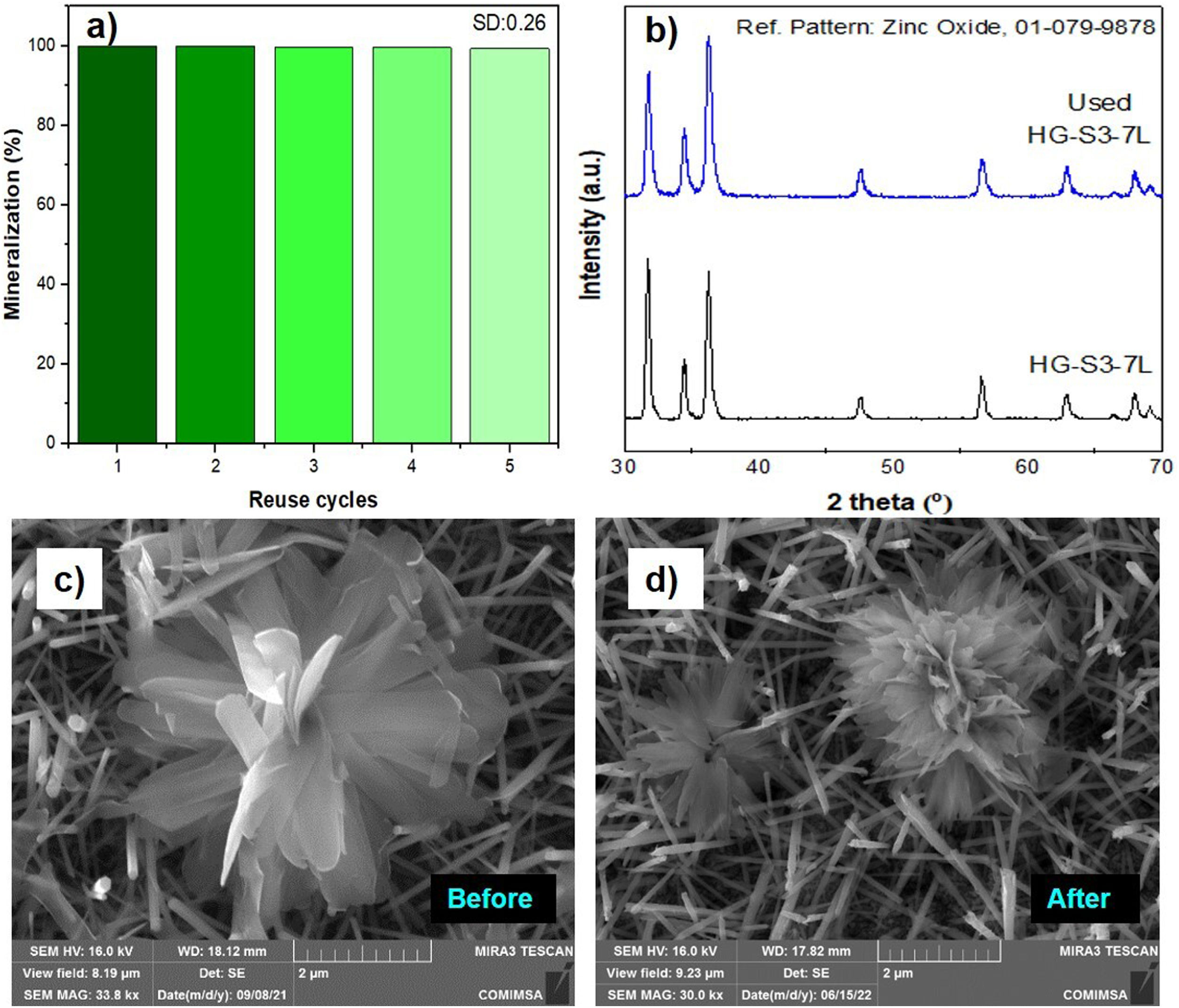
A feature of a photocatalyst is its reusability. Fig. 13 shows the percentage results of the performance of the HG-S3-7L film system during five consecutive reuse cycles mineralization efficiency kept the range of 100–99.4%, with a standard deviation of ±0.26. This stability is because the ZnO wurtzite crystal structure (Fig. 13b) and the morphology of the ZnO coatings (Fig. 13c, d) are similar before and after the reuse cycles. It indicates that the 1D and 3D nanostructures obtained in this work have high stability during five reuse cycles for the photocatalytic mineralization of MB under the reaction conditions presented.
Conclusions Reuse cycles using ZnO, (b) X-ray diffraction, ZnO micrograph (c) before and (d) after the reuse cycles.")
The synthesis conditions of the seed layer (spin coating) have an impact on the final morphology of the nanostructure depending on the number of layers deposited, the greater the number of seed layer deposits, the alignment behavior oriented in the planes is favored (100), (002) and (101). Therefore, the combination of the spin-coating technique to deposit ZnO prepared by sol–gel and then grow up ZnO nanostructures by the hydrothermal method demonstrates that it is possible to obtain coating on glass substrates with the growing of nano and microstructures in the form of nanorods and ZnO micro flowers.
The best results obtained in the dye degradation were for the HG-S3-7L film system attributed to the synergy obtained between the two morphologies (flowers and rods) that promote electronic migration between ZnO and the dye. Consequently, the morphology of ZnO coatings with hydrothermal growth acts as an efficient photocatalyst in the methylene blue degradation obtaining a 100% degradation in a time of 120min for the HG-S3-7L system.
Conflicts of interestThe authors declare no conflict of interest.
Authors thank to UJAT for the facilities, Antonia del Rocío López Guemez acknowledges the scholarship provide by CONACYT. Laura Lorena Díaz Flores thanks Project CB CONACYT 2015 number 256221. We also thank Dr. Juan C. Díaz Guillen Cátedra CONACYT-COMIMSA Saltillo for technical assistance in SEM and XRD measurements.

