


Cordierites have exceptional thermal stability and resistance to thermal shock, rendering them particularly attractive for various industrial applications. Nonetheless, their mechanical properties are relatively modest when compared to other technical ceramics. Besides, their applicability is limited due to the simplicity of shapes achievable through current processing techniques. Reinforcing cordierite with graphene together with advanced manufacturing holds the promise of substantially enhancing their properties, thereby expanding their utility. This study establishes the groundwork for employing ceramic injection moulding (CIM) in the production of complex shape parts made of cordierite reinforced with reduced graphene oxide (rGO). The adequacy of direct rGO addition to the binder components for obtaining homogeneous rGO/powder dispersions and feedstock with good rheology is assessed. The debinding and sintering conditions are adjusted to maintain the graphemic species avoiding their degradation. The prevalence of graphene is tracked and demonstrated in all CIM steps by X-ray analysis and Raman spectroscopy. Sintered parts with properties exceeding that of base cordierite are accomplished, paving the way for innovative applications of cordierite–rGO composites in diverse industrial contexts.
Las cordieritas poseen una estabilidad térmica excepcional y una alta resistencia al choque térmico, lo que las hace particularmente atractivas para diversas aplicaciones industriales. Sin embargo, sus propiedades mecánicas son relativamente modestas en comparación con otras cerámicas técnicas. Además, su aplicabilidad está limitada debido a la simplicidad de las formas que se pueden lograr con las técnicas de procesamiento actuales. El refuerzo de la cordierita con grafeno junto con la fabricación avanzada ofrece la promesa de mejorar sustancialmente sus propiedades, ampliando así su utilidad. Este estudio establece las bases para el empleo del moldeo por inyección de cerámica (CIM, por sus siglas en inglés) en la producción de piezas de formas complejas hechas de cordierita reforzada con óxido de grafeno reducido (rGO). Para ello, se evalúa la idoneidad de la adición directa de rGO a los componentes del sistema ligante para obtener dispersiones homogéneas de rGO/polvo y materias primas con buena reología. Se llevó a cabo un estudio pormenorizado de las condiciones de eliminación y sinterización, que se ajustaron para evitar su degradación. A su vez, se hizo un seguimiento de la prevalencia del grafeno en todas las etapas del CIM mediante análisis de rayosX y espectroscopia Raman. Los resultados demuestran que el CIM permite el desarrollo de componentes cerámicos reforzados con grafeno de alta complejidad geométrica, logrando piezas sinterizadas con propiedades superiores a las de la cordierita base. Este estudio abre el camino para aplicaciones innovadoras de los compuestos de cordierita-rGO en diversos contextos industriales.
Cordierites, comprised of magnesium aluminosilicates, stand out for their high thermal stability and remarkable resistance to thermal shock across a wide range of temperatures. These properties are mainly provided by the primary α cordierite phase with stoichiometry 2MgO–2Al2O3–5SiO2. Their excellent thermal properties make them valuable in applications where withstanding extreme temperature variations is paramount. For instance, cordierites are extensively utilized in automotive catalytic converters, which experience rapid and drastic temperature changes during operation. Additionally, they play a vital role in industrial furnaces and kilns, enduring high temperatures for consistent and reliable operation.
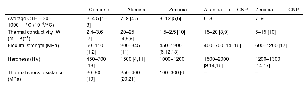
Apart from α cordierite, other phases are commonly present in cordierites. They are promoted and adjusted by changing the stoichiometric composition of Al2O3, SiO2 and MgO and the sintering conditions to attain a wide range of mechanical and functional properties like electrical resistivity. In particular, the presence of mullite is sought to enhance the mechanical performance. Table 1 shows typical thermal and mechanical properties ranges attainable in cordierites and a comparison with that of alumina and zirconia. Their low coefficient of thermal expansion in a wide range of temperatures is a key factor contributing to their notable thermal shock resistance. In comparison, high-performance ceramics like alumina and zirconia exhibit higher coefficients of thermal expansion, making them more susceptible to thermal stresses. However, though cordierites offer satisfactory mechanical properties, fall short when compared to other high-performance ceramics like alumina and zirconia.
Comparison of the main properties of cordierite, alumina and zirconia.
| Cordierite | Alumina | Zirconia | Alumina+CNP | Zirconia+CNP | |
|---|---|---|---|---|---|
| Average CTE – 30–1000°C (10−6/°C) | 2–4.5 [1–3] | 7–9 [4,5] | 8–12 [5,6] | 6–8 | 7–9 |
| Thermal conductivity (W (mK)−1) | 2.4–3.6 [7] | 20–25 [4,8,9] | 1.5–2.5 [10] | 15–20 [8,9] | 5–15 [10] |
| Flexural strength (MPa) | 60–110 [1,2] | 200–345 [11] | 450–1200 [6,12,13] | 400–700 [14–16] | 600–1200 [17] |
| Hardness (HV) | 450–700 [18] | 1500 [4,11] | 1000–1200 | 1500–2000 [9,14,16] | 1200–1300 [14,17] |
| Thermal shock resistance (MPa) | 20–80 [19] | 250–400 [20,21] | 100–300 [6] | – | – |
In addition, the processing technologies for cordierites primarily encompass techniques such as extrusion, dry pressing, and slip casting. While these methods have proven effective for certain applications, they come with inherent limitations when it comes to the cost-effective production of large batches of complex geometries, intricate details, and components with consistently tight tolerances. This fact, added to their modest mechanical properties, restricts the use of cordierites in complex shape applications where stringent mechanical demands are also prevalent, as in e.g. aerospace components.
This work proposes and explores the use of ceramic injection moulding (CIM) for the manufacture of complex-shaped components made of cordierite–mullite matrix composites reinforced with graphene. The incorporation of small fractions of graphene as reinforcement has shown remarkable potential in enhancing the properties of ceramics, particularly in materials like alumina and zirconia. As shown in Table 1, graphene–alumina and graphene–zirconia composites exhibit substantial enhancements in fracture toughness, flexural strength, and hardness. These promising outcomes call for the investigation and development of cordierite–graphene composites to yield similar improvements. Additionally, graphene is renowned for its exceptionally high thermal conductivity and thus, the addition of graphene into the cordierite matrix could significantly enhance cordierite's thermal conductivity. This enhancement directly translates into heightened resistance to thermal shock, as the graphene–cordierite composite would distribute and dissipate heat more effectively, reducing the potential for thermal stress-induced fractures.
There are several challenges associated with the processing of ceramics reinforced with graphene that motivates ongoing research and development in the field. While graphene boasts exceptional properties, its cost-effective large-scale production remains a limiting factor for its widespread use in ceramic composites. Pure graphene in the form of platelets (GNPs), is the most desirable reinforcement due to its inherent properties, albeit it is also the most expensive. On the other hand, graphene oxide (GO) and reduced graphene oxide (rGO) present more industrially viable and cost-effective alternatives that maintain many of the advantageous properties of GNPs. Regardless of the selected variant, achieving a uniform dispersion of graphene within the ceramic matrix remains a significant challenge. Uneven distribution can lead to localized reinforcement, compromising the overall material properties. Graphene sheets tend to agglomerate due to van der Waals forces, which also hinder their effectiveness as a reinforcement. Developing effective dispersion techniques favouring deagglomeration is crucial for realizing the full potential of these advanced composites. Various methods are employed to achieve effective dispersion and deagglomeration of graphene, including high-energy ball milling, ultrasonication, and the use of surfactants. Each technique aims to break down agglomerates, allowing for better integration of graphene into the ceramic matrix.
This study critically analyzes the benefits and challenges associated with integrating rGO into cordierite powder using CIM. CIM presents numerous advantages for manufacturing complex-shaped graphene-reinforced ceramics. The process involves initially mixing the ceramic powder with a melted binder to create a feedstock, subsequently injected into a mould cavity. Post-injection, the binder undergoes a debinding stage, followed by sintering to achieve the final ceramic component. CIM's efficiency enables the cost-effective production of large, intricately shaped cordierite composites. Furthermore, the binder used in CIM serves as a potential medium to effectively disperse and deagglomerate graphene, facilitated by the shear forces exerted during mixing. However, the effectiveness of graphene dispersion and its interaction with the binder and ceramic powder requires meticulous assessment. Ensuring optimal bonding between graphene and ceramic particles is crucial, necessitating careful consideration of their interactions without compromising graphene stability. Challenges are anticipated, particularly in maintaining graphene integrity through debinding and sintering stages, critical for cordierite sintering at high temperatures. This study primarily focuses on methodically tracking graphene presence throughout all CIM stages, aiming to elucidate challenges and devise strategies for enhancing the integration of graphene in the cordierite matrix.
Materials and methodsMaterialsThe base ceramic powder was delivered by Vicar S.A. The company adjusted the powder milling conditions to make it suitable for use in CIM. This ceramic powder has a D50 particle size of 2.68μm and a Sw value of 2.1, indicating a wide particle size distribution that is well-suited for CIM [22,23]. This powder is a combination of various oxides, as demonstrated in Table 2, which will ultimately yield the desired cordierite–mullite composition upon reactive sintering. The formation of phases like mullite and alumina has a positive effect on the cordierite properties, though it impairs the low CTE attainable by single-phase cordierite. The reduced graphene oxide (rGO) powder was generously supplied by LayerOne Advanced Materials. The rGO is primarily composed of approximately 80% carbon (C) and 20% oxygen (O), with impurities making up less than 1% of its weight. It exists as agglomerates of rGO sheets with a flake-like structure, each having an average length of 14±6μm. The binder employed is a typical polyolefin-based binder [3,24], consisting of polyethylene as the primary polymer, paraffin wax serving as a lubricant, and stearic acid acting as a surfactant.
Feedstock preparation and injectionIn a preliminary study, the optimal solid loading for plain cordierite powders within the designated binder system was determined to be 63vol.% [3]. Consequently, a feedstock with this cordierite fraction, without reinforcement, was processed as a reference and denoted as COR. This reference helps to understand the influence of rGO addition on the feedstock's features and behaviour in subsequent CIM steps.
The incorporation of rGO is expected to affect the rheological characteristics of the cordierite feedstocks. It is crucial to ensure uniform dispersion of the feedstock constituents and to disentangle the rGO sheets to prevent the formation of large agglomerations, which could negatively impact the material's properties. As a preliminary approach, 0.25wt.% of rGO, relative to the weight of the cordierite powder, is evaluated as a reinforcement. This feedstock, containing 63vol.% of cordierite and the rGO reinforcement, is denoted as COR-rGO. However, it is important to note that the apparent density of rGO powders is very low, at 0.007g/cm3 according to the manufacturer, meaning that small weight fractions will initially occupy a relatively large volume. While this volume is expected to significantly decrease during the mixing process, it may influence both the mixing process itself and the properties of the feedstock.
An initial assessment was conducted to investigate a pre-mixing approach involving rGO powders combined with paraffin wax, which was melted at 60°C and mechanically stirred. Subsequently, all components were thoroughly blended using a Haake Rheocord torque rheometer, facilitating a comparative analysis of feedstock mixing. The operational parameters for this mixing process included a temperature of 160°C and roller rotor speeds of 30rpm. All feedstocks underwent rheological characterization using a TA Discovery device set up as a plate-plate oscillatory rheometer with 25mm diameter circular plates, operated at 150°C.
The feedstocks were processed into pellets of approximately 2mm in size, suitable for use in an Arburg Allrounder injection moulding machine. The molten pellets were then injected into a prismatic mould with dimensions of 12mm×66mm×4mm, following the specifications for bending test specimens as per ASTM E290 14 standards.
Debinding and sinteringIn this study, a two-step debinding process was implemented. Initially, the injected specimens were immersed in heptane at 60°C for 5h, followed by drying in a desiccator furnace at 60°C for 1h. Subsequently, the specimens underwent a thermal cycle in a nitrogen-protective atmosphere. The dwell temperatures and heating rates of the thermal cycle were determined based on thermogravimetric analyses detailed in the following section.
The brown specimens were sintered in a tubular furnace under different protective atmospheres including nitrogen, argon and a vacuum of 1×10⁻³bar. This cycle involved a controlled heating rate of 2°C/min until reaching a target temperature of 1340°C, which was maintained for 1h before allowing the furnace to cool naturally. The sintering temperatures were previously established for cordierite powders [3], aiming to achieve maximum densification while obtaining a convenient combination of phases.
To directly compare and isolate the effects of rGO reinforcement, identical sintering conditions to those used for the base material were maintained. This approach aims to identify the specific contributions of rGO to the composite's properties, such as reducing residual porosity. Despite the high sintering temperature, concerns regarding the thermal degradation of rGO are alleviated by its inherent thermal stability and the use of an inert vacuum atmosphere. Graphene and its derivatives, including rGO, are known to withstand high temperatures without significant degradation [25–27]. Therefore, the selected sintering conditions should preserve the structural integrity of rGO. This assumption is crucial for our exploratory work, which aims to utilize CIM to integrate rGO into cordierite effectively.
Materials characterizationScanning electron microscopy (SEM) was performed using a JEOL model JSM-6610LV to characterize the morphology of cordierite and rGO powders, assess the homogeneity of the feedstocks, and analyze the microstructure and fractography of the sintered specimens. The sintered specimens were cut along cross, transversal and longitudinal dimensions and polished to a 1μm diamond previous to microstructure evaluation. Element maps were created using the SEM electron dispersive X-ray (EDX) probe to assist with phase identification in the characterized materials.
Thermogravimetric analyses (TGA) were conducted using a LabSys evo TGA on raw rGO powders and feedstocks. The thermal cycles consisted of a temperature ramp of 5°C/min, from 50°C to 600°C, in an inert nitrogen atmosphere with a flow rate of 40mL/min.
A LECO CS230 was employed for combustion non-dispersive infrared (NDIR) analysis to determine the carbon content in raw powders and specimens at various stages of processing. Raman characterization was carried out using an InVia Renishaw micro-spectrometer with a 532nm point-based laser and a power density below 1mW/μm2. X-ray diffractograms were collected using a Philips (Panalytical) X’Pert MPD diffractometer in a 2θ range of 5°–50° at a scan rate of 0.01°/min, utilizing Cu Kα1 radiation (0.154056nm) at 40kV and 40mA. The XRD peak indexing, phase fraction determination, and calculation of crystalline domain size were performed using Full Profile Search Match software [28], which utilizes the crystallography open database (COD) and the Rietveld method for fitting XRD diffractograms.
Mechanical testsMicrohardness and fracture toughness tests were carried out on the polished specimen surfaces using a Digital Future-Tech FM-7 series tester. A load of 9.8N was applied for 10s using a Vickers diamond pyramid indenter. Indentation testing is a straightforward method to estimate fracture toughness and is used as an alternative to other methods requiring complex geometries. Among the different methods available in the literature, the empirical formula from Evans and Charles [29,30] shown in Eq. (1), was selected in this study as it results in fracture toughness values close to that reported for cordierites [31]. The fracture toughness (KIC) in MPam0.5 depends on the Vickers microhardness (HV), the crack half-length (c), and the indentation size (a) in meters, parameters obtained directly from the hardness test.

The bending properties were measured through a three-point bending test method, following ASTM E290-14 standard dimensions for bending test specimens. The bending test was performed in a Shimadzu Autograph AG-X machine equipped with a 50kN load cell. The specimens were subjected to a deformation rate of 1mm/min, with the deflection at the specimen's centre (δ) recorded as the machine's displacement. According to beam theory, the bending stress (σf) is calculated from the applied force (F) using the following equation:
where b is the specimen width, a is the specimen height, and L, the separation of the supports, is 40mm in this study. To assess the thermal shock resistance, EN 820-3 was followed. Bending specimens were heated to 300°C for 15min and then quenched in water at room temperature. Then the flexural strength is evaluated and compared to that of as sintered specimens.ResultsMixing and feedstock characterization
Mixing is a key step in the rGO reinforced cordierite fabrication that must ensure and homogenous and uniform distribution of all the feedstock constituents. Besides, it is expected that mixing will be effective in the deagglomeration of the rGO powder. The efficacy of mixing is evaluated in this section. In CIM technology is well stablished that the study of the mixing torque and rheology evaluation through different devices are reliable methods to assess the homogeneity of dispersed ceramic particles. The present study presents two relevant issues to be considered: (1) the powders consist of a mixture of different cordierite precursor particles, (2) the incorporation of rGO could affect the dispersion of other binder constituents. Hence, the uniform dispersion of the feedstock constituents will be complementary evaluated by other methods.
Fig. 1 illustrates the torque evolution during the mixing of the two prepared cordierite feedstocks without and with rGO addition. Both feedstocks exhibit similar mixing behaviour. As the components are progressively added to the mixing chamber during the first 20min, the torque increases. Once all compounds are incorporated, the torque reaches its maximum value, indicating the formation of powder particle agglomerates [32,33]. These agglomerates contribute to high friction and low packing, resulting in increased feedstock viscosity. Subsequently, the torque gradually decreases with mixing time until it stabilizes at 0.9±0.1Nm and 1.4±0.1Nm for COR and COR-rGO respectively. The decrease in torque can be attributed to the breakage of powder agglomerates and the gradual incorporation of power particles by the binder. When the torque stabilizes, it signifies an equilibrium between the addition and segregation of the melted binder within the solid components. This equilibrium is often associated with achieving a homogeneous dispersion of all feedstock constituents. Furthermore, the introduction of a small fraction of rGO (0.25wt.%) significantly alters the torque values compared to the base sample evidencing that the rGO addition has a pronounced impact on feedstock rheology.

Supplementary Fig. S1a and b shows SEM images of COR and COR-rGO feedstocks after mixing along with EDX elemental composition maps. The binder embeds the ceramic particles. A uniform distribution of the different precursor powders is observed without the formation of agglomerates. This observation is not significantly affected by the addition of rGO and is in line with the torque curves.
As the SEM micrographs did not allow to evaluate the rGO dispersion and thus Raman spectroscopy measurements were carried out. Fig. 2 shows a comparison of the spectra obtained through Raman spectroscopy of COR and COR-rGO feedstock. The COR feedstock exhibits low-intensity peaks, which correspond to the deformation, bending and rocking of CH2 and CH3 groups in both paraffin [34] and PE [35]. Two intense peaks are observed, in contrast, in the COR-rGO feedstock that is identified as the characteristic D and G bands of graphene at 1350 and 1580cm−1, respectively. It is worth noting that the characteristic peaks of the binder are masked by the intense rGO peaks, though might be affecting the intensity and curve shape in COR-rGO. Hence, any interpretation analyzing these parameters should be done with care.
 Raman spectra for green samples COR and COR-rGO. (b) Color Raman maps of samples COR and COR-rGO.")
The G band is associated with crystallinity, while the D band pertains to defects. The increase in the intensity and width of the D band is related to the increase in the number of defects and disorders [36]. Besides, the intensity of D peak, if there is no other factors influencing the defects, can be linked to the number of layers in graphene [37]. The ID/IG ratio for the COR-rGO feedstock is 0.47, almost half of the 0.83 value measured for the raw rGO powder. The decrease of the D-band intensity after mixing with the rest of the feedstock components indicates a reduction of defects, which in this particular case is associated with the decrease of the number of layers in deagglomerated rGO powder due to the effect of mixing. Hence, though the value obtained suggests the presence of multilayer reduced graphene oxide as deduced from the literature [38], mixing has a significant effect on the rGO deagglomeration.
Fig. 2b shows Raman color maps of the two studied feedstock. As expected, COR specimen maps show mostly dark regions due to the absence of Raman signal at specific ID and IG Raman shifts. Anecdotical spots are related to localized high fluorescence of some feedstock particles, and thus are considered an artifact. Regions exhibiting high intensity of the ID and IG signals in COR-rGO indicates the presence of rGO sheets. The size of these sheets agrees with that of the raw rGO powder with ∼10μm. A uniform dispersion of these sheets is observed, emphasizing the effectiveness of mixing. However, specific regions with particularly high intensity might be indicating multilayer rGO.
To further delve on the interaction of the different feedstock components, differential scanning calorimetry (DSC) experiments were carried out. DSC is an interesting technique to assess the dispersion of graphene in a polymer matrix [39]. Particularly, results could assess the effectiveness of incorporating rGO by a preliminary dispersion in paraffin wax. Fig. 3 shows the DSC curves of the different studied feedstocks. Three distinctive endothermic peaks are observed. The two consecutive peaks occurring at low temperatures are associated with first-order phase transitions of paraffin: (a) solid-solid transition from monoclinic to hexagonal pseudo crystal structure (∼40°C) and (b) a solid–liquid transition and isotropisation (∼56°C). The peak occurring at ∼120°C is related to melting of high-density polyethylene. Table 3 shows a comparison of the peak temperatures and enthalpies of fusion of the different compounds and feedstocks extracted from DSC.

Normalized heat of fusion and melting temperature of different feedstock components’ peaks measured in the second differential scanning calorimetry heating compared to that of pure components.
| PWS→S | PWS→L | HDPE | ||||
|---|---|---|---|---|---|---|
| ΔHm(J/g) | Tm(°C) | ΔHm(J/g) | Tm(°C) | ΔHm(J/g) | Tm(°C) | |
| Paraffin (PW) | 24.2 | 37.3 | 117.3 | 55.4 | – | – |
| HDPE | – | – | – | – | 225.8 | 131.6 |
| COR | 16.3 | 35.9 | 106.1 | 55.5 | 256.7 | 120.1 |
| COR-rGO | 12.7 | 37.2 | 86.5 | 57.2 | 156.1 | 121.5 |
The COR specimen showed a significant reduction of the melting temperature of HDPE, while that of paraffin wax was barely altered. A modification of both paraffin wax and HDPE heat of fusion is also observed, with a slight decrease in the former and an evident increase in the latter. This is explained by the interaction of the feedstock components, including the paraffine with HDPE and the cordierite powder with the binder components and will not be further discussed here. We focus on the effect of rGO addition, which is analyzed using the COR feedstock (0wt.% rGO) as a reference. The peak temperatures of paraffine and HDPE exhibit negligible increment (1–2°C) with the addition of rGO. However, the addition of a small fraction of rGO had a substantial impact on the heat of fusion, causing a drastic reduction of approximately 30% for the melting peaks.
It is generally evidenced by DSC [39,40] that increasing fractions of GO nanoparticles significantly reduce the paraffin's heat of fusion and crystallization. For graphene additions below 2wt.%, the variation in phase change temperatures remains minimal. This behavior is attributed to the unique structural features of GO, such as carbon and oxygen bond arrangements, sp2 hybridization, hydrophilic properties, molecular sieves, and organic covalent functionalization. The addition of graphene limits the ordering capacity of polymer chains like polystyrene, thereby decreasing the heat of fusion [41]. Balan et al. [39] also reported a linear decrease in paraffin crystallinity with increasing multilayer graphene nanoplate fractions. This was explained by the interaction between graphene layers and paraffin chains, which disrupts their alignment, impedes crystallization, and consequently reduces the phase transformation enthalpies.
However, some studies [41–44] have shown that, under specific conditions where graphene is well-dispersed and strongly interacts with the polymer matrix, the heat of fusion may increase compared to that of the pure polymer. This discrepancy highlights the critical role of dispersion quality and interfacial interactions between graphene and the matrix. In this study, interpreting the DSC results is particularly challenging due to the complexity of interactions among the feedstock components, including paraffin, HDPE, and rGO. Despite this complexity, the observed reduction in the heat of fusion of the binder components suggests that rGO effectively inhibits crystallization. This behavior supports the hypothesis of good incorporation and dispersion of rGO not only in paraffin but also in HDPE. Moreover, Raman mapping results confirm the presence of multilayer rGO and its uniform distribution within the feedstock, aligning with the trends observed in DSC data and previously reported in the literature. These findings suggest that the interaction between rGO and the binder disrupts the molecular ordering of polymer chains, reducing crystallinity and the corresponding enthalpy changes [39–44].
DebindingFig. 4 shows the thermogravimetry curves of COR and COR-rGO feedstocks in the green state, i.e. as injected. Two clear weight loss steps can be observed. The first step, occurring between 200 and 350°C, corresponds to the thermal degradation of paraffin wax (∼11wt.%). The rest of the binder components are mostly thermally eliminated between 425 and 500°C. The theoretical powder fraction is 84.4wt.% for COR feedstock and 84.2wt.% for COR-rGO feedstock. Considering an equipment error of ∼0.2wt.%, a quantitative measurement of organic residue is meaningless. However, it can be concluded that most of the organic components have been degraded in the COR specimen and some residue remains above 500°C in COR-rGO, which matches well with the theoretical addition of rGO.

It is worth mentioning that the addition of rGO has a notable effect on the degradation of paraffin wax, shifting the degradation curve to lower temperatures. This shift is indicative of strong interactions between paraffin wax and rGO, as evidenced by the TGA and DSC results. While the DSC results suggest that some interactions might exist between rGO and HDPE, the effect on the degradation of the other binder components, including HDPE, appears to be negligible. This indicates that rGO primarily interacts with paraffin wax within the binder system, with minimal impact on the thermal stability of HDPE.
The TGA curves of the feedstocks in the called blue state (that is the state of debinding after solvent but before thermal debinding), included in Fig. 4, show that most of the paraffin was eliminated after the solvent debinding. The weight loss primarily corresponds to the complete degradation of HDPE. In the case of COR-rGO, the final weight is higher than that for the COR specimen. This is in agreement with the TGA of the green specimens and suggests that rGO is maintained after the debinding combining solvent and thermal process. Indeed, there is no clear evidence of rGO presence in the solvent evaluated by Raman spectroscopy, which leads to the conclusion that most of the rGO is maintained in the blue specimen.
Carbon measurements were performed in brown specimens to further analyze the residue after debinding. The results are presented in Table 4. The carbon content measured in the COR specimen matches with the TGA result and confirms that a minor carbonous residue remains after debinding. The reinforced specimen exhibits a carbon content higher than that of COR. The carbon difference in both specimens represents a good estimation of the contribution to the carbon of species other than the binder residue. This value is in the order of the rGO addition and makes thinking that most of the rGO prevail after debinding. Indeed, thermogravimetry analysis of the rGO powder, indicates that severe rGO degradation in a nitrogen atmosphere occurs beyond 500°C and that more than 70wt.% remains after continued temperature raising to 900°C. This thermal stability is important to withstand the sintering conditions, which are discussed in the following sections.
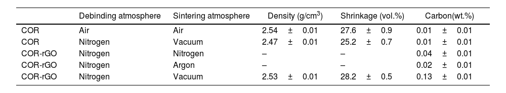
Selection of sintering conditionsThree protective sintering atmospheres were explored to prevent thermal degradation of rGO during sintering: nitrogen, argon and vacuum (10−3bar). The resulting sintered specimens were compared in terms of visual inspection (defects), densification, shrinkage and carbon content to determine the influence of the sintering atmosphere on these properties. The reinforced specimens were contrasted with plain cordierite counterparts subjected to a conventional debinding and sintering cycle in air and a combination of debinding and sintering in nitrogen and vacuum, respectively. This is done to assess any effect of the selected atmospheres on the cordierite microstructure and properties that could be isolated from the effect of rGO addition. Fig. 5 shows a cross-section of cordierite-reinforced specimens sintered at different atmospheres and Table 5 shows the properties obtained after the different studied conditions.

Data on debinding and sintering atmospheres, density, shrinkage (vol.%) and carbon (wt.%) of the different cordierite samples.
| Debinding atmosphere | Sintering atmosphere | Density (g/cm3) | Shrinkage (vol.%) | Carbon(wt.%) | |
|---|---|---|---|---|---|
| COR | Air | Air | 2.54±0.01 | 27.6±0.9 | 0.01±0.01 |
| COR | Nitrogen | Vacuum | 2.47±0.01 | 25.2±0.7 | 0.01±0.01 |
| COR-rGO | Nitrogen | Nitrogen | – | – | 0.04±0.01 |
| COR-rGO | Nitrogen | Argon | – | – | 0.02±0.01 |
| COR-rGO | Nitrogen | Vacuum | 2.53±0.01 | 28.2±0.5 | 0.13±0.01 |
Although the sintering atmosphere seems to have barely any effect on the final carbon of COR sintered specimens, sintering in argon and nitrogen proved ineffective in preventing graphene degradation, leading to notable defects that disqualify these conditions for further studies. The argon atmosphere caused significant carbon loss, evident from the colour change, shifting from white at the specimen surface to dark grey at the core, and the measured low carbon values. Additionally, blisters formed on the specimen surface, causing substantial shape distortion, while cracks developed within the specimen. Similar outcomes were observed in specimens sintered in nitrogen. However, in this case, the discolouration resembling the white tone of cordierite appeared more superficial, limited to a reduced thickness. Although the carbon content was notably higher than in the argon sintering, it fell far short of the expected values considering the added rGO weight fraction. This indicates a considerable loss of rGO. The degradation of rGO at high temperatures under these conditions might result in a buildup of pressure if the degradation vapours are not effectively extracted, causing the observed defects.
Promising results are obtained, however, with the vacuum sintering atmosphere. The cross-section is uniformly coloured in dark grey and there is a notorious lack of defects. The carbon content is high compared to the rest of the specimens. Still, the carbon content is halfway to the 0.25wt.% of rGO. This divergence would not be fully explained if a complete reduction of rGO, containing approximately 20wt.% of O, had occurred. It is plausible that a fraction of the rGO was degraded and evaporated during the sintering, though it has to be considered that the combustion infrared spectroscopy might have limitations in the carbon evaluation due to the high stability of graphene with temperature.
The density and shrinkage of reinforced specimens are higher than that of the plain cordierite counterparts sintered at the same conditions and are equivalent to the values attained in the plain cordierite using an air debinding and sintering atmosphere. This suggests that the addition of rGO facilitates cordierite densification in a vacuum atmosphere. It is worth mentioning that the plain cordierite specimen sintered in a vacuum atmosphere exhibits a light greyish colouration, contrasting with the white colour characteristic of the cordierite sintered in air. However, clarity is lacking about the nature of this colouration as the carbon is equivalent and low in both cases. These unresolved queries will be discussed in “Characterization of sintered specimens” section after a more thorough characterization.
Characterization of sintered specimensFig. 6a shows a LOM image of a sintered COR-rGO specimen. The microstructure is similar to that observed in the sintered cordierite, exhibiting several features characteristic of a multiphase composition. Porous are observed in both specimens. The main difference between the two conditions is the observation of dark fibrillar features. These features sometimes line up following an accordion fashion, as indicated by a dotted line in Fig. 6a, and resemble an unfolded rGO agglomerate as shown in the SEM image of Fig. 6b. Indeed, the size of the dark fibres matched well with that of the rGO sheets. This suggests that the rGO sheet piles are separated by ceramic powder particles during the mixing process.
 LOM image of sintered COR-rGO specimen. The dotted line indicates the identification of a possible rGO agglomerate (G) unfolded in an accordion fashion. (b) SEM of the raw rGO resembling the accordion feature identified in (a).")
Fig. 7a shows the cumulative intensity Raman spectra of sintered cordierite and reinforced cordierite composite, while Fig. 7b presents the Raman mapping. The cordierite specimen produced minimal Raman interactions for the D and G graphene bands, consistent with observations in the green specimen. This indicates that the formation of carbon species during sintering, due to ineffective carbon degradation, is negligible and unlikely to misinterpret the results in reinforced cordierite. In the rGO-reinforced specimen, high luminescence spots, which match the shape and size of rGO sheets, are evident confirming the presence of graphene species after sintering. Although some dark regions are observed, the dispersion of graphene species is uniform. The cumulative intensity of both bands is notably reduced compared to the green specimen (see Fig. 2) aligning with the carbon percentage measured by LECO and indicating some graphene loss during sintering. The ID/IG ratio in the cumulative spectra is 0.30, lower than in the green part, suggesting a general reduction in defects and the number of layers. However, sporadic map regions exhibit ID/IG ratio close to 1, indicating that the detected graphene species are either defective or with high number of layers.
 Raman spectra for sintered samples COR and COR-rGO. (b) Color Raman maps of samples COR and COR-rGO.")
A magnified SEM image of COR and COR-rGO microstructures is presented in Fig. 8. The numbers indicate EDX point analysis of characteristic features, and results are shown in adjacent table. Equivalent microstructural features are observed in both specimens. The matrix (1) exhibits an elemental composition corresponding to that of cordierite. Elongated relieved features (2) with a similar tone as the matrix, sharp edges, and principally containing aluminium and oxygen, are identified as alumina particles. Although the features (4), (3), and the pores (P) exhibit similar visual characteristics, the EDX analysis reveals distinct elemental compositions for features (4) and (3), confirming the existence of different phases within the microstructure. Specifically, the roughened ellipsoidal features (4) are rich in silicon, indicating a possible identification as amorphous SiO2, while the dark grey spots (3) correspond closely to mullite stoichiometry, primarily composed of aluminium and silicon. In COR-rGO the pores appear to be filled with a differentiated feature (5) in the reinforced specimen, as shown complementary shown in magnified image of Fig. S2. This feature is composed of high carbon and oxygen and matches with the rGO composition and size.

Regarding porosity, the estimated percentage with image analysis software (ImageJ [45]) of COR specimen reaches 9% of the area, with an average pore size of 70±30μm. Fully dense cordierite ceramics are difficult to achieve by reactive sintering [46]. This depends on the sintering temperature, the method of obtaining the parts, as well as the proportion of the different raw powders and the evolution of phases during sintering. In COR-rGO, the pore size (30±10μm) and population (3%) were significantly reduced compared to that of the COR condition.
Fig. 9 displays the diffractograms of the cordierite samples obtained with and without graphene. The primary phase formed is α-cordierite. Additionally, mullite (3Al2O3·2SiO2) is identified, along with alumina (Al2O3). The narrow and sharp diffraction peaks indicate the high crystallinity achieved in both samples. Nonetheless, in the 2θ range of 15°–30° a pronounced bump was observed in both materials that is identified as a SiO2-based glass phase. The peak intensity variability of the different phases in the two materials indicates a variable fraction of microstructure constituents. The estimated phase volume fractions of the different phases are shown in Table 6. The addition of rGO has a notorious influence on the phase fraction, exhibiting high fraction of cordierite and a low fraction of the glass phase. The estimated relative density considering phase quantification is also show in Table 6. The high densification of the COR-rGO specimen is in line with the measured porosity.

Phase percentages from XRD analysis and relative density calculated using the rule of mixtures with theoretical phase densities.
| vol.% (±2%) | α-Cordierite | Mullite | Alumina | Amorphous SiO2 | ρrel |
|---|---|---|---|---|---|
| COR (air) | 28 | 47 | 14 | 11 | 87.0 |
| COR (vacuum) | 21 | 55 | 12 | 12 | 84.5 |
| COR-rGO | 46 | 38 | 11 | 7 | 87.4 |
| Densities (g/cm3): α-cordierite=2.53, mullite=3.00, alumina=3.99, amorphous SiO2=2.20 [4,18,49] | |||||
In the COR-rGO specimen, the peak at 2θ=10° corresponding to the (100) plane of cordierite is skewed to low 2θ and is wider compared to its 0wt.% rGO counterpart. This is associated with the presence of a graphemic species. Graphene oxide (GO) shows a characteristic broad diffraction peak at 2θ=∼10° and as the GO is reduced, this peak is shifted to higher 2θ[47]. Indeed, the (002) plane diffraction peak is detected at 2θ=∼25° in the raw rGO. The identification of (002) peak at 2θ=∼10° suggests that rGO could have interacted or reacted with the raw oxides powders or the –OH groups in the powder surfaces to functionalize back to GO. This would promote a good interaction of the GO with the ceramic matrix, which is favourable to enhancing the mechanical performance of the composite [48].
As discussed earlier, the incorporation of rGO significantly reduces both the pore size and population in the COR-rGO condition compared to COR. This reduction in porosity aligns with the relative density results presented in Table 6, which show values of 84% for COR in vacuum, 87% for COR in air, and 87.4% for COR-rGO. These findings reinforce the conclusion that adding rGO enhances densification, not only by reducing porosity but also by promoting a more compact and homogeneous microstructure.
The sintering process in the reference COR specimen likely involves viscous flow facilitated by the formation of a liquid phase from added alkali oxides, a mechanism commonly documented in the literature [3,50] and is in agreement with the observation of a liquid phase. This liquid phase aids densification by enhancing particle rearrangement and reducing the activation energy for sintering enabling the reduction of porosity as described earlier. Simultaneously, a solid-state reaction between SiO2, Al2O3, and MgO leads to the formation of cordierite and intermediate phases like mullite, with liquid phase-assisted diffusion further contributing to the process. The presence of isolated alumina particles within the microstructure suggests incomplete sintering, potentially due to local non-uniformities in the distribution of precursor powders. Interestingly, while the sintering atmosphere – whether air or vacuum – does not significantly affect the phase fraction composition, it has a notable impact on densification. Typically, vacuum or reduced-pressure environments facilitate the expulsion of internal gases through a pressure gradient, which should reduce porosity and enhance densification [51]. However, this contrasts with the current findings. The efficacy of liquid phase sintering depends on the equilibrium of surface and capillary pressures among the system's constituents, which can be influenced by the sintering pressure. Furthermore, the absence of oxidizing gases in vacuum conditions may alter the formation of transient phases and lead to the volatilization of certain elements. This, in turn, could modify the nature and properties of the liquid phase, potentially affecting its effectiveness in pore closure and densification.
The presence of rGO seems to promote a more controlled and efficient densification process likely by enhancing grain boundary diffusion and potentially altering the sintering atmosphere. This leads to better densification and a higher fraction of cordierite in the final product. Chae et al. [52] compared sintering in an air atmosphere with a mildly reducing atmosphere in the presence of CO in cordierite ceramics. Compared to air, reductive atmospheres resulted in a notable reduction of pore size and a more uniform pore size distribution. Besides, the crystallization rate of cordierite and indialite from the liquid phase was markedly accelerated under these reducing conditions, resulting in a significantly lower residual liquid phase than observed under oxidizing conditions. These variations in sintering behavior are attributed to differences in liquid-phase viscosity, influenced by higher concentrations of CO under reducing conditions. High-viscosity liquid phases tend to coalesce, forming larger pores, whereas lower-viscosity phases spread more effectively over the crystal surfaces, leading to finer pore structures. These results can be extrapolated to present work in which evidenced decomposition of rGO during the sintering could locally form a reductive atmosphere, influencing the viscosity of the liquid phase and reducing the pore fraction and residual liquid phase compared to the reference COR specimen. This densification mechanism would be also favoured by the remanent graphemic species for higher densification. Trusova et al. [53] reported an improvement of the densification of zirconia due to the presence of graphene. It appears that van der Waals interactions contribute to the partial stabilization of the zirconia structure by graphene sheets. This stabilization inhibits the disordering of surface zirconia monolayers and prevents their premelting. This results in an increase in the composite's sintering activation energy and introduce complexity to its sintering mechanism. Analysis of the data indicates that, with graphene sheets present, sintering follows a mixed mechanism dominated by grain boundary diffusion, unlike pure zirconia, which primarily undergoes sintering through a viscous flow stage. These mechanisms might be also operative in sintering of cordierite reinforced with rGO, enhancing the densification.
Mechanical behaviourHardness and fracture toughnessMicrohardness and fracture toughness were evaluated in three characteristic sections of the bending test to assess potential property anisotropy resulting from the injection process. The results are depicted in b---ox and whisker plots of Fig. 10 and averaged values are shown in Table 7.
 hardness and (b) fracture toughness results.")
Average hardness and fracture toughness results for the COR and COR-rGO measured at three different sections.
| HV 1kg | KIC [MPam0.5] | |||||
|---|---|---|---|---|---|---|
| Cross | Transversal | Longitudinal | Cross | Transversal | Longitudinal | |
| COR | 580±40 | 600±40 | 590±30 | 2.0±0.3 | 2.2±0.2 | 2.4±0.3 |
| COR-rGO | 600±40 | 600±30 | 690±50 | 2.3±0.2 | 2.4±0.4 | 2.7±0.4 |
The high variability in microhardness results (approximately 150HV) for both COR and COR-rGO specimens can be attributed mainly to the multiphase microstructure and eventually to the presence of pores, which locally influence hardness. The COR specimen exhibited consistent hardness across all three sections, with values within the typical range for cordierites [18]. The reinforced cordierite (COR-rGO) showed an average hardness increase of approximately 50HV (around 9%) in the transverse and lateral sections. Notably, a significant anisotropy was observed at the top surface of COR-rGO, with hardness values often exceeding those of the base material by up to 150HV. Considering that the COR-rGO has a lower fraction of hard alumina and mullite phases compared to the COR specimen, the increase in hardness due to the addition of rGO is significant. This is partially explained by a low pore fraction, though this should not significantly influence the measurements as micro indentations were done avoiding pores. The greater variability in hardness observed in COR-rGO can likely be attributed to the scale of rGO dispersion within the final microstructure relative to the size of the micro indentation (∼50μm). Indentations near graphene-rich areas exhibit significantly increased hardness, while regions further from these species show hardness values similar to the reference specimen.
Similar to hardness, fracture toughness is positively influenced by the addition of rGO, consistent with the literature on graphene-reinforced ceramics where graphene acts as a crack deflection and bridging agent, enhancing toughness. Anisotropy in fracture toughness is observed in the COR specimen, and this pattern is also evident in the reinforced specimen. This suggests that the processing may induce microstructural anisotropy, which significantly affects toughness more than hardness and is not solely explainable by the presence of rGO. However, a more comprehensive microstructural analysis is required to confirm this hypothesis. The high variability in fracture toughness results for COR-rGO is consistent with that observed with hardness and is explained by the same effects.
The significant anisotropy observed suggests the spatial orientation of rGO sheets, likely resulting from variations in local cooling rates or flow patterns during the injection process. These factors might induce a preferential alignment of the graphene sheets in the flow direction, as schematized in Fig. 11. The high shear forces during injection would also contribute to the delamination of multilayer graphene sheets. These hypotheses are supported by existing literature on the extrusion and injection moulding of graphene-reinforced polymers [54,55]. Fractography SEM images of the three sections – transversal (y–z), lateral (x–z), and the top surface (x–y) – are shown in Fig. 12 detailing spots where graphene is identified. In the transversal and lateral sections, graphene sheets appear as stretched, layered structures embedded within the matrix. These sheets exhibit a wrinkled texture and are partially protruding from the surrounding material as if they are emerging from the matrix. They are commonly associated with pores and elongated cavities. In the top section, the graphene sheets mainly appear more extended and spread out over the surface. The sheets cover a larger area and show fewer wrinkles compared to the transversal and lateral sections. Although this is a general observation, indicating a preferential orientation of the graphene sheets, examples of both descriptions can occasionally be spotted in all sections. The possibility of using CIM to align graphene sheets in composite ceramics, thereby significantly enhancing their properties, presents an unexpected yet exciting result. This frontier area in materials science is attracting considerable research interest, as finding an effective method to achieve such alignment in graphene-reinforced composites remains a complex and demanding challenge.
Bending and thermal shock resistance
 Cross-section, (b) lateral section, and (c) top section.")
Fig. 13 shows the flexural strength results for COR and COR-rGO in the as-sintered (AS) and after thermal shock treatment (TS). The average flexural strength of cordierite is also enhanced by the reinforcement, though it increases more moderately (∼6%) than the hardness. The results dispersion is high in COR-rGO, and some specimens exhibit values in the order or lower than that of the achieved by plain cordierite. However, some specimens also exhibit significantly high flexural strength.
 and thermal shock-treated (TS) specimens.")
To better analyze the resulting variability, the Weibull analysis procedure described in Annex I was applied and Weibull plots for the specimens sintered with COR and COR-rGO are displayed in Fig. 14. The data for the COR sample demonstrates a relatively good fit for the Weibull distribution. Compared to the COR-rGO specimen, the variability in flexural strength of the COR specimen is notably lower, leading to a higher β parameter. The characteristic strength of plain cordierite increases by 17% with the addition of rGO, highlighting the efficacy and potential of the CIM process to produce graphene-reinforced composites. This improvement is evidenced in the comparative probability plots of the two materials.
 Weibull probability plots and fit trend line to a linear equation and the R2 fitting parameter; (b) B-ox and whiskers plot comparative of the flexural strength; (c) Weibull cumulative distribution showing the probability of failure at a certain flexural stress.")
Weibull and statistical analysis of flexural strength results of COR and COR-rGO sintered specimens: (a) Weibull probability plots and fit trend line to a linear equation and the R2 fitting parameter; (b) B-ox and whiskers plot comparative of the flexural strength; (c) Weibull cumulative distribution showing the probability of failure at a certain flexural stress.
However, the reinforced specimens show a high dispersion of results, and the fitting to the Weibull model is less accurate. The observation of two distinct linear trends in the COR-rGO data, characterized by differing Weibull moduli, suggests multiple failure modes. Repeating the Weibull analysis with the six lowest flexural strength values in COR-rGO resulted in a similar β (8.6) and equivalent σ0 (77.5) to that of the COR, indicating that the failure mechanisms prevalent in cordierite are maintained in the reinforced specimen. Nevertheless, the introduction of rGO has promoted mechanisms that delay failure and thus, on average, improving the flexural strength. These results align with the hardness of the different specimens. The prevalence of multilayer graphene in the sintered specimen, however, can have a pernicious effect on the ceramic composite, favouring the formation and propagation of cracks [56]. The material under study is a ceramic, which inherently exhibits brittle fracture behavior. In this context, both the initiation and propagation of fractures are highly dependent on very localized defects. In the specimens with rGO, the agglomerates of multilayer graphene act as preferential sites for fracture initiation and propagation, increasing the inherent tendency of ceramic materials to display high variability in their mechanical properties. This might explain why the reinforced specimens exhibit a certain probability of breaking at stresses lower than those for plain cordierite (see Fig. 14). Despite this, the results highlight the potential of the novel processing method used, which achieved notable outcomes even with highly agglomerated rGO powder. Further improvements in variability could be achieved by using graphene powders with superior characteristics.
An improvement of the flexural strength following thermal shock testing is evident in COR specimens (see Fig. 13). This is even more pronounced in COR-rGO, which is particularly interesting as it indicates that the composite exhibits a very high thermal shock resistance. The hypothesis proposed in this study suggests that thermal residual stresses are generated during the thermal shock test due to the difference in thermal expansion coefficients between different phases present in the microstructure, particularly between graphene and the ceramic matrix. These residual stresses may cause crack propagation to occur in a more tortuous manner, thereby increasing the flexural strength after thermal shock. This hypothesis is supported by the work of Tan and Yang [57] discussing the various hardening phenomena that occur when nanomaterials are introduced into ceramics. The authors suggest that the residual stresses induce local weakening, which translates to global hardening by impeding crack propagation. However, further detailed study of this property is necessary to validate these results and to determine the limits beyond which this increase ceases to occur, whether due to the continued repetition of thermal shock cycles or due to initiating them from a higher temperature difference.
ConclusionsThis work explored the use of ceramic injection moulding for the processing of reduced graphene oxide reinforced cordierites, focusing on the characterization of the capacity of the wax-based binder to disperse the graphene and the surveyance of graphene during the different processing steps. The following conclusions were extracted from the study:
- -
Ceramic injection moulding emerged as a promising processing technology for the production of graphene-reinforced cordierites. The graphene incorporation processes through the wax binder component and subsequent mixing step with cordierite powder were evidenced effective for the deagglomeration and homogeneous dispersion of rGO.
- -
Although there was a sign that most of the rGO prevailed after the combined solvent and thermal debinding step, a fraction of graphene appeared to be lost after selected sintering conditions. In this regard, a vacuum atmosphere stood out over argon or nitrogen-protective atmospheres in maintaining high fractions of rGO.
- -
The rGO showed a marked influence on the densification and phases developed after sintering, resulting a positive effect on the hardness, fracture toughness, bending strength and thermal shock resistance of the studied cordierite composition. This is explained by the inherent effect of the reinforcement and indirectly by a reduction of the porosity.
- -
The results point to a preferential alignment of the graphene sheets in the injection flow direction, which should be further studied and understood due to its potential to attain tailored and improved properties in specific component directions thanks to the CIM processing technology.
The explored process offers significant advantages for the straightforward and cost-effective integration of graphene and other 2D reinforcements into ceramics. While the initial results are promising, further optimization of processing conditions – such as the rGO fraction, incorporation methods, and sintering temperatures – along with refining the properties of raw materials, is anticipated to further enhance the already encouraging outcomes.
We want to acknowledge the contribution of V. González-Velázquez and E. Vazquez by conducting and interpreting Raman's results. This work was supported by the project AERORECORD3D, funded by MCIN/AEI/10.13039/501100011033/FEDER, EU-PID2021-125612OB-C21. Dr. Javier Hidalgo acknowledges his postdoctoral researcher contract under the University of Castilla-La Mancha's own R&D&I Plan, jointly financed by the European Social Fund (ESF) and the European Social Fund Plus (ESF+) via project 2022-UNIVERS-11006 and contract 2022-POST-20884.
The Weibull distribution has proven effective in describing a large range of problems including the mechanical behaviour of brittle materials [ref]. In a Weibull analysis, the probability of failure F at a given flexural strength σ can be calculated using the Weibull probability cumulative distribution function (CDF) as expressed in Eq. (A.1):

The scale parameter σ0 also referred to as characteristic strength, defines the stress that causes failure in approximately 63.2% of the specimens, i.e. F(σ0)=1−(1/e). Meanwhile, β, known as the Weibull modulus, characterizes the width of the fracture distribution and serves as an indicator of material homogeneity, reflecting the range of flexural strength variation. A high value of β suggests a high degree of homogeneity and a narrower spread in flexural strength.
Various procedures exist for deriving Weibull parameters, including linear regression methods like the Weibull plot, weighted linear regression, and maximum likelihood estimation, with the Weibull plot being the most prevalent and straightforward method for parameter determination. The β and σ0 parameters are determined through linear regression analysis using the following equation:

In this work the Fi for each data point is estimated by:

where Ri is the rank of the ordered data points starting from 1 (smallest value) to n (largest value), and n is the number of data points of the ordered data (in this case n=10).
The following are the supplementary data to this article:

