

The building described hereunder is an example of the importance of early stage cooperation between the architectural and structural engineering teams in establishing design guidelines that capitalise on the full potential of architectural forms to maximise structural effectiveness and minimise the impact on functionality. One such guideline is the “megastructure” concept, whereby the overall shape of a building is used to generate a large-scale structural member. The solution for the iconic element of the design at issue (a huge curved cantilever) was to optimise façade and structural slab performance by eschewing additional elements (such as diaphragm walls, masts or tie beams) that would affect the aesthetics of the building exteriors or constitute an invasion of the indoor space.
El edificio del que trata el presente artículo es un ejemplo de cómo una temprana colaboración entre los equipos de Arquitectura y Estructuras permite la aplicación de pautas de diseño que aprovechan la potencialidad de la forma arquitectónica para lograr estructuras de máxima eficacia y mínima afección a la funcionalidad.
Entre esas pautas de diseño se encuentra el concepto de «megaestructura», por el cual se utiliza la forma global del edificio para generar una estructura de gran escala. De esta manera, el elemento icónico del proyecto (un gran voladizo de eje curvo) es resuelto mediante la optimización del comportamiento de fachadas y forjados, evitando la introducción de elementos adicionales (pantallas, mástiles, tirantes, etc.) que afecten al aspecto exterior del edificio o resulten invasivos para el espacio interior.
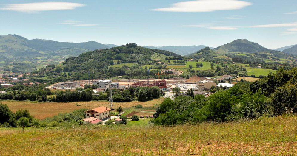
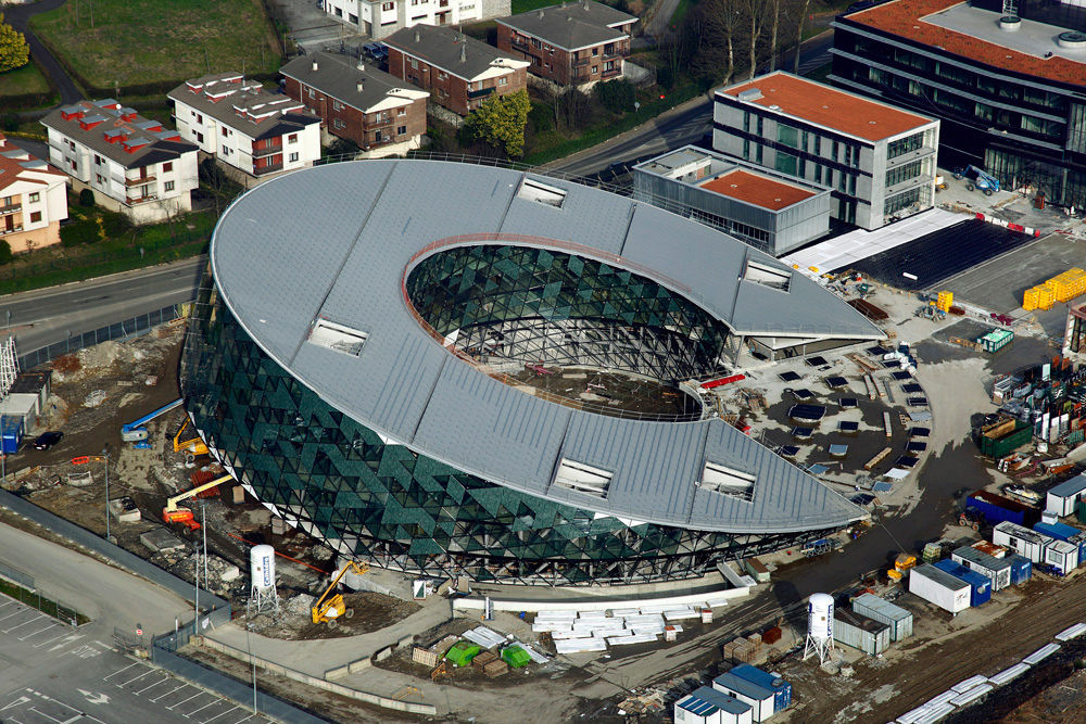
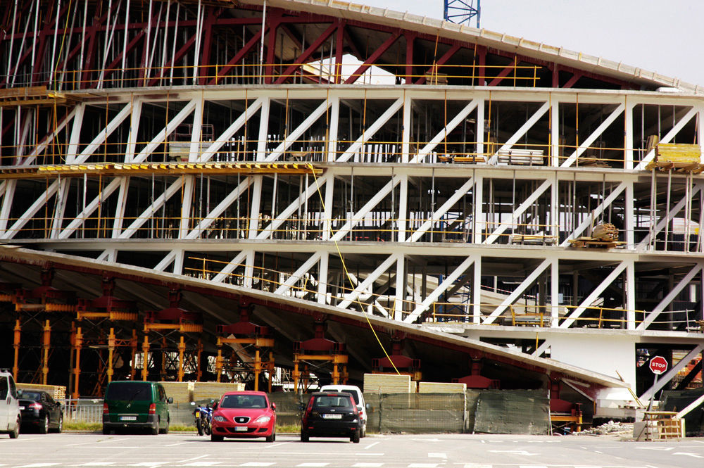
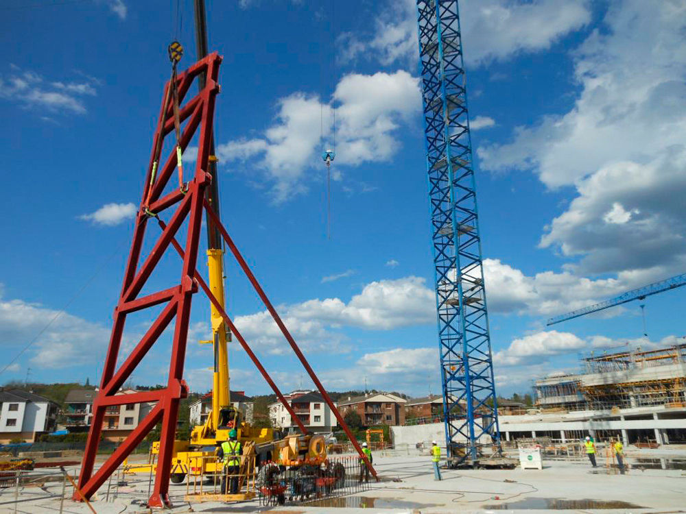
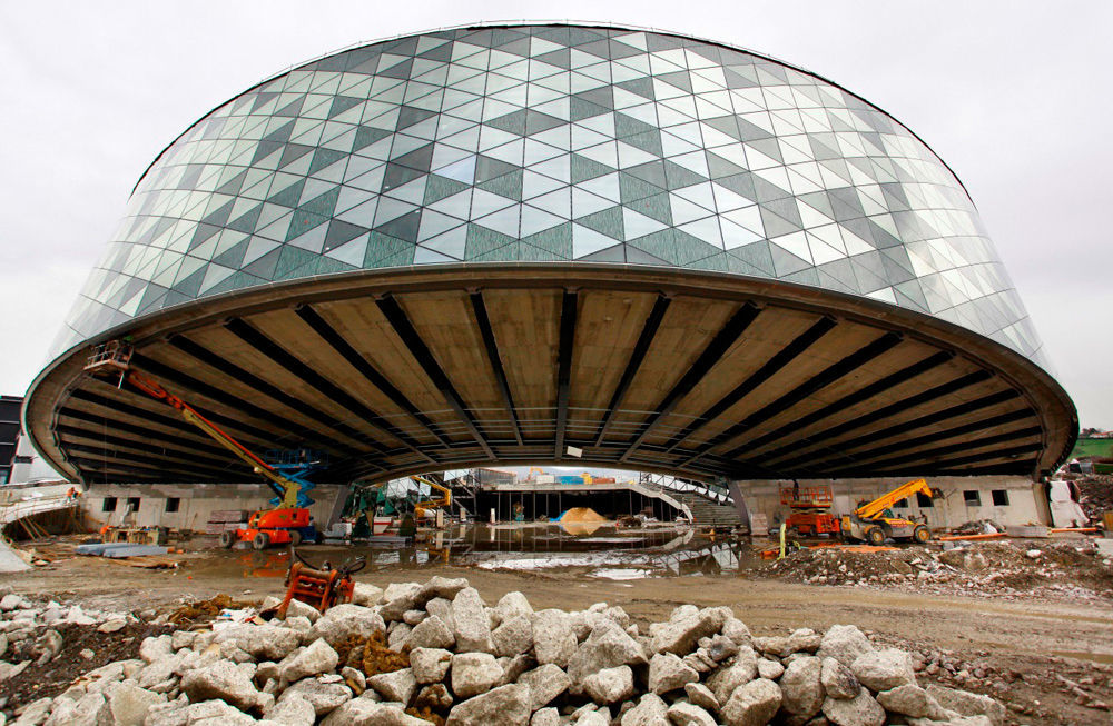
The Orona Zero building is the most prominent structure in the new Orona Ideo Innovation City complex built to house the corporate headquarters and R&D+i facilities of the eponymous lift design, construction and assembly company as well as one of the corporation's University of Mondragón faculties. The compound, located in Galarreta industrial estate at Hernani in the Spanish province of Guipúzcoa, is a project of substantial magnitude both from the standpoint of the investment involved and its impact on the peri-urban surrounds where it is located (Fig. 1).

The building itself represents the iconic image of a new brand geared particularly to sustainability. In addition to its indisputable aesthetic and functional values, then, the design envisaged the minimisation of energy consumption from external sources and construction to LEED and BREEAM sustainable building standards [1,2].
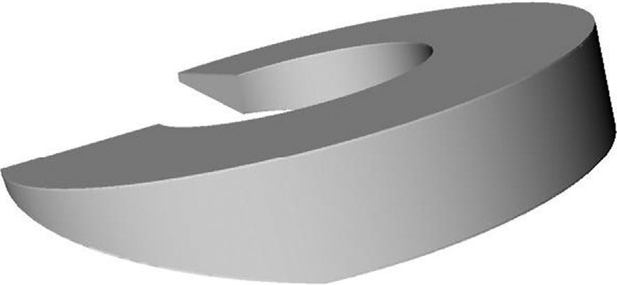
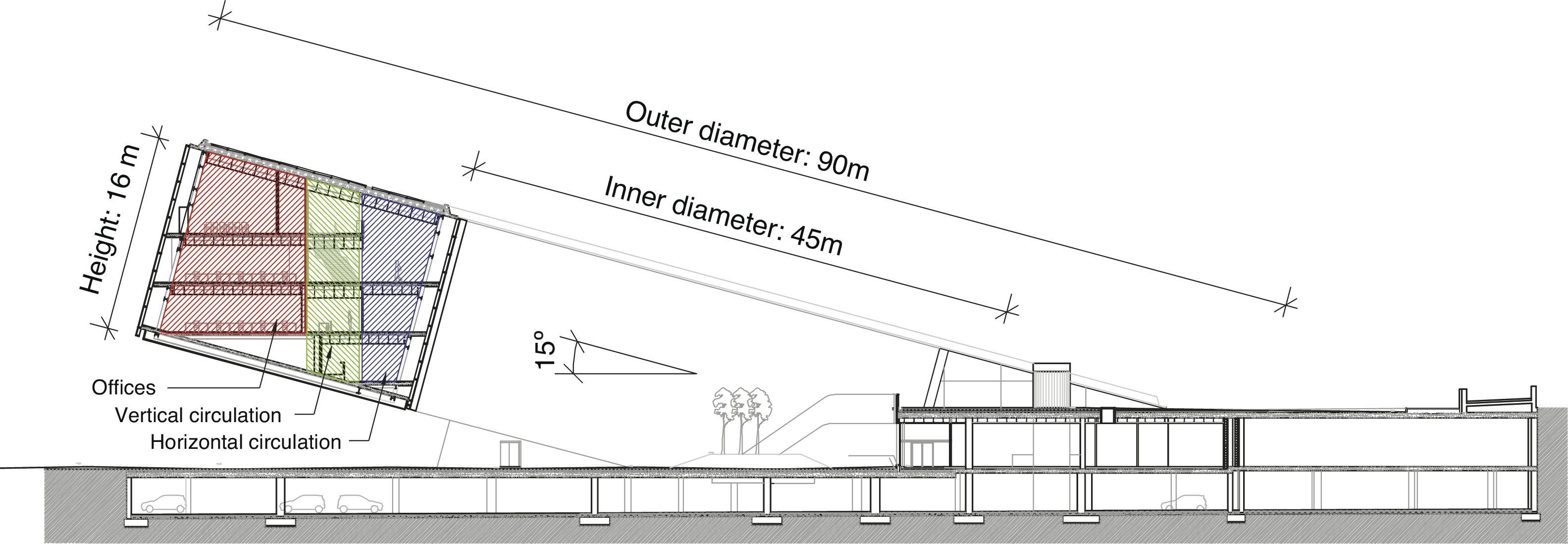
2Architectural designInspired by the company's logo, the building has a singular geometry: the space generated by a hollow cylinder 16m high with a 90m outer and a 45m inner diameter and open on the lower side to accommodate the hardscaping. As it slants at a 15° angle off the vertical, the volume generated cantilevers over the ground. This volume main dimensions are 26m measured perpendicularly to the support axis, a cantilever spanning 30m, and an outer façade arch 102m long between supports (Fig. 2).

The building houses four 4-metre high (structural floor, centres) office storeys plus a split-level entrance storey and a basement car park. The design was impacted in a number of respects by the elliptical shape of the office storeys, the result of their non-normal angle to the axis of the cylinder. The storeys do not cover the full area of the ellipse due to the constraints imposed by the roof and bottom structural slabs and the hardscaping. Consequently, the angle swept varies from storey to storey.
Given its quasi-circular shape, the building layout is based on polar coordinates with a system of radial and circumferential axes into which two vertical cylinders are inserted, dividing the storeys into three concentric functional spaces or annuli: work areas (outer annulus), vertical circulation (central annulus) and horizontal circulation (inner annulus). The dimensions of these annuli differ on each storey inasmuch as they are organised around the intersection of the outer slanted cylinder and the aforementioned vertical cylinders (Fig. 3).

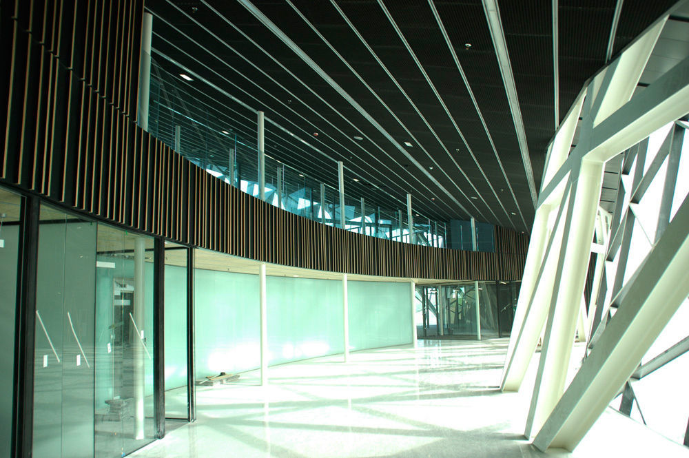
The building's axis of symmetry runs northwest–southeast for optimal sunlight. The outdoor-facing premises receive natural light indirectly through an exterior curtain wall to avoid the glare on digital screens, whereas the inner circulation areas receive direct light, enhancing their function as places for rest and relaxation. The glazed inner façade opens onto the courtyard around which the complex revolves and which serves as an antechamber for the building.
As a counterpoint to such a distinctly polar system, the design of the pitched roof is based on the horizontal lines perpendicular to the maximum slope defined by the banks of photovoltaic panels that source the electric power for the building. Parallel to these lines, five square balconies provide outdoor space for users, a feature highly appreciated in curtain wall buildings with non-openable windows (Fig. 4).

Design and construction conformed to the ‘nearly net zero energy’ criteria that pursue the minimisation of external energy consumption with energy savings systems, self-generation and energy transfer among the systems in place in the building [3].
3Structural design3.1General conceits. Background to the design approachThe pursuit of ‘megastructure’ in the initial stages of design as an engineering recourse to capitalise most effectively on architectural form is one of the tools which, under a broader concept known as ‘tensibility’, is one of the leitmotivs of the structural engineering that has characterised MC2 in recent years [4].
‘Tensibility’ can be defined from two perspectives [5]:
- •
the capacity to use the maximum envelope dimensions of the entire building, as actively as possible, to establish a structural system for that space, able to solve strength and construction problems without altering the spirit of the architectural form proposed;
- •
the intrinsic capacity of a structural arrangement or typology to lead the forces induced by the actions on a structure, as directly and actively as possible, towards the supports or load transfer points.
The aim, then, is to identify the strength mechanisms afforded by the elements designed by the architect, to generate the spaces or project the images that define the building and maximise its effectiveness. Examples of the application of this concept can be found in Spain's Pavilion at the Shanghai World's Fair [6], the ‘bamboos’ in the ZeroZero tower on Barcelona's Diagonal Avenue [7] and the overlapping diaphragm walls on Madrid's Teatros del Canal [8].
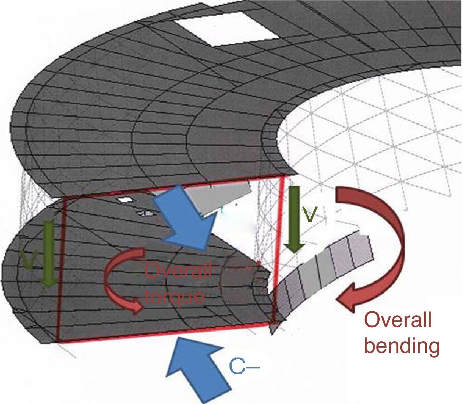
3.2General description of the structureThe structural approach originally adopted was to regard the pitched top and bottom sloped slabs and the inner and outer trusses as the members comprising the overall strength system. This huge cylindrical box girder would be able to withstand the loads generated in the cantilevered area by drawing from non-uniform torque mechanisms and transfer such loads to the support areas in contact with the conventional structure below. The general stress generated by the unique cantilever (around 30m between the outer edge and its closest support) would induce overall bending and shear stress and torque in the ‘megastructure’. These would translate primarily into axial tensile forces on the top and compression on the bottom sloped slab, irrespective of the attendant shear stress on both planes. The trusses, in turn, would transfer the basic overall shear to the columns through the tensile and compressive mechanisms acting on the vertical, and diagonal web members, and the horizontal chords [9] (Fig. 5).

In this conceptual approach, overall torque, induced by the circular form of the element, would be introduced in the system via the tangential stress on the large rectangular section formed by the four aforementioned sub-systems (two sloped and two curved truss planes). Nonetheless, due to their incompatibility with building functionality, bulkheads or cross-braces stiff enough to keep the section from warping and hence justifying the assumption of pure torque in the design were not envisaged for such a section. In other words, the structural system would entail additional deformability and the elements would be exposed to compatibility forces characteristic of the non-uniform torque induced in the portal frames formed by the truss uprights and the structural slab beams as a result of the slope on the latter.
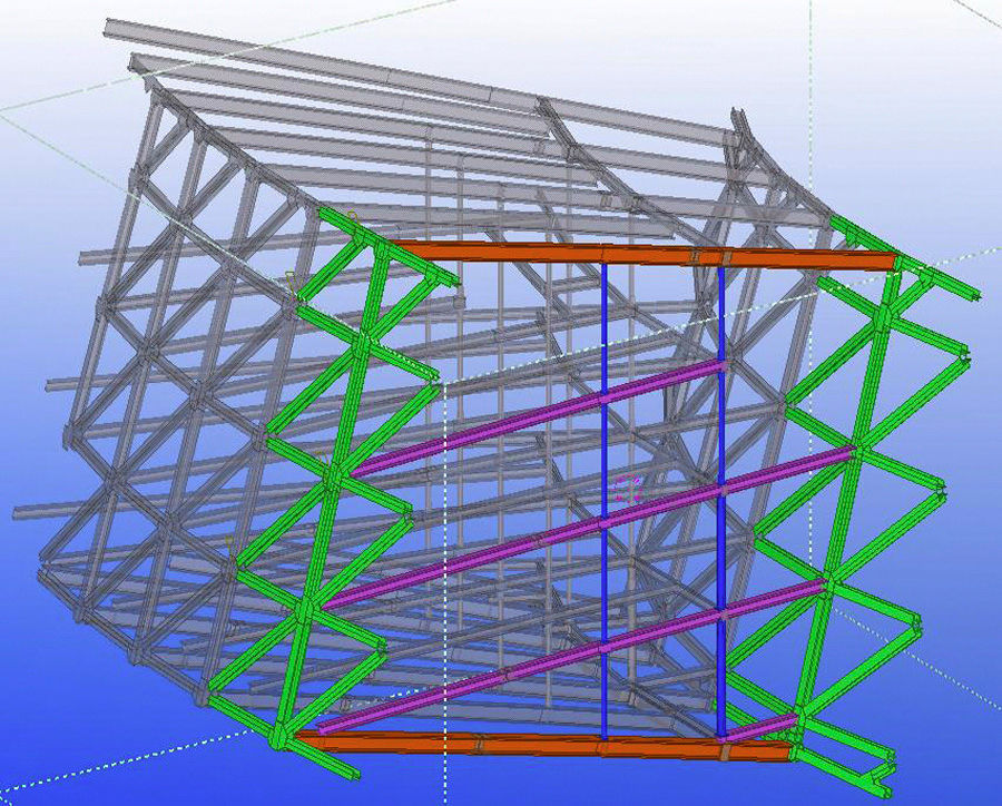
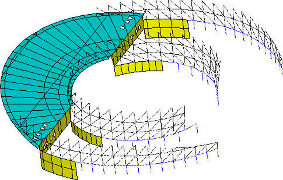
The inter-storey beams and floors and inner columns constituted the secondary elements in this general system. In addition to constituting the architectural storeys, they were to serve an indisputable purpose within overall structural behaviour by acting, depending on their stiffness and the design of their connections, as intermediate diaphragms, countering to some limited extent the deformability of the huge box girder that comprises the ‘megastructure’ (Fig. 6).
 and the bottom and roof structural slabs (orange for beams) is stiffened by diaphragms consisting in the inter-storey beams (purple) and inner tubular columns (blue).")
Radial cross-section of the 3D model of the steel structure. The box girder section formed by the façade trusses (green in the diagram) and the bottom and roof structural slabs (orange for beams) is stiffened by diaphragms consisting in the inter-storey beams (purple) and inner tubular columns (blue).
The main structural elements are described in the following sections.
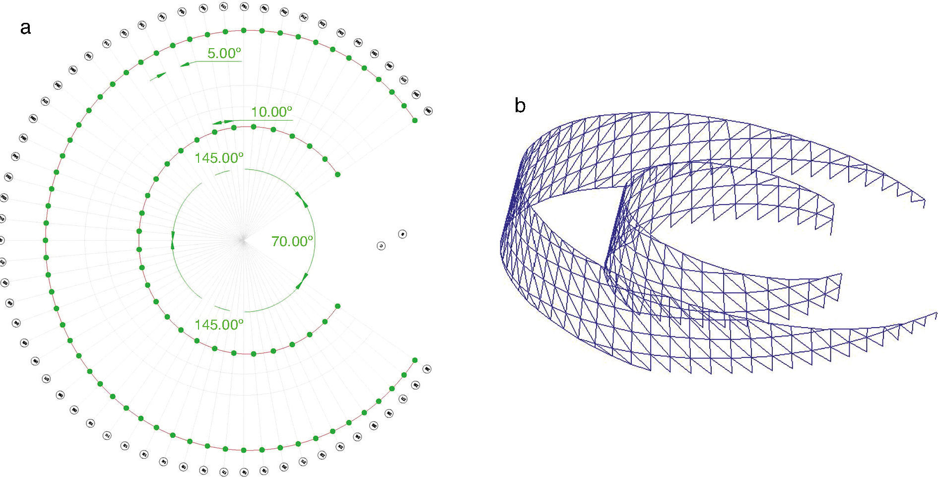
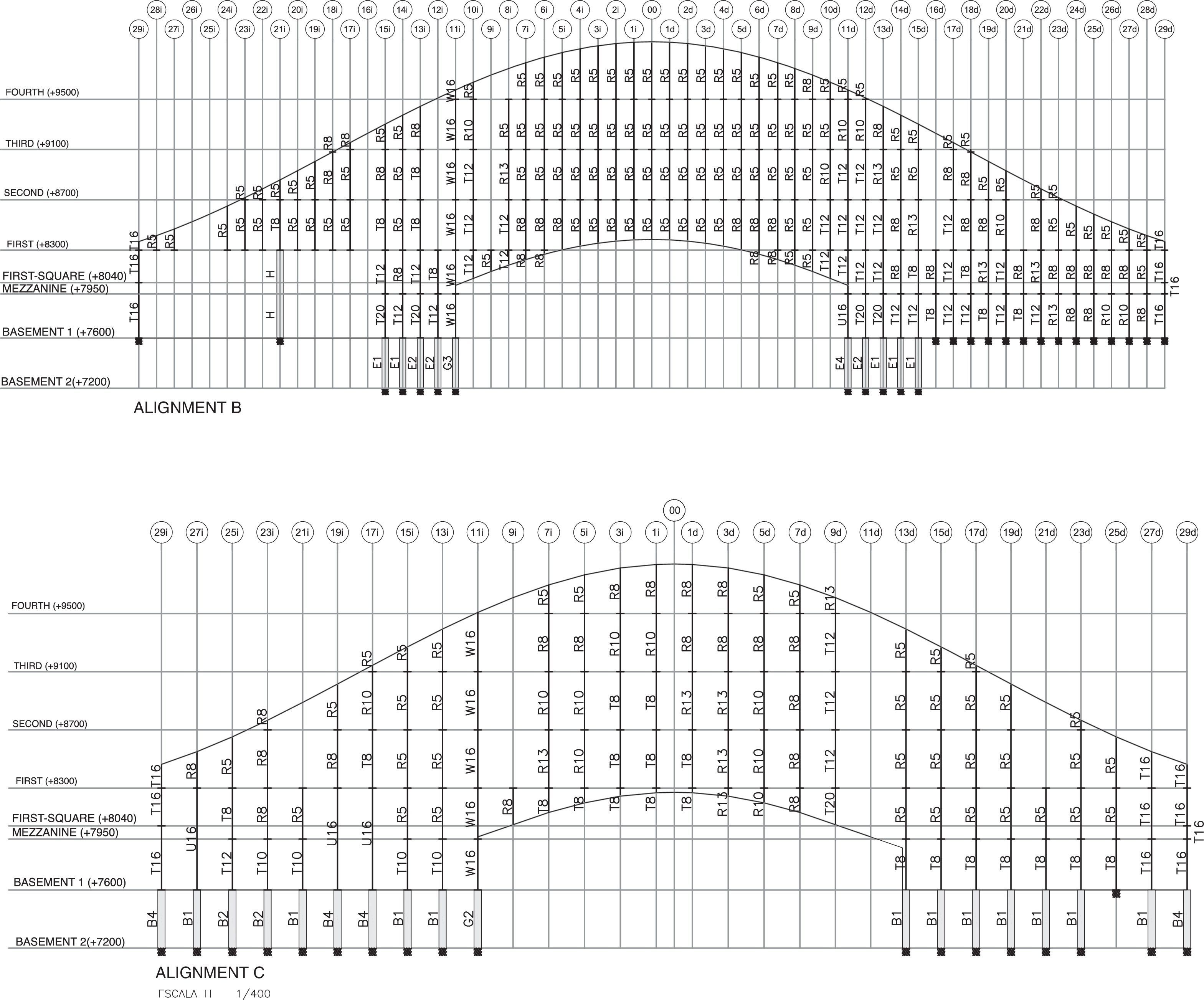
3.3Main trussesThe building's trusses are its primary bearing members. The approximately square modules (4m between uprights, 4m between storeys), originally intended as a constant module for the second storey, ultimately translated into a sheaf of vertical planes set at 5° angles to one another. While the truss on the outer cylinder approximately doubles the diameter of the truss on the inner cylinder, since only one of every two outer axes continues on to the inner structure, the modules in the latter could also be dimensioned to approximately 4m2. Both trusses sweep a total angle of 290° symmetrically around axis 00 (Fig. 7).
 and three-dimensional modelling (right).")
Although curved, the trusses are made of straight elements that join the nodes at the theoretically curved surfaces. The maximum deflection (chord deviation with respect to the arc) is around 50mm.
A number of alternatives for the trusses were initially considered (Howe with one or two families of diagonals, with or without vertical uprights, Viereendel truss without diagonals…). Ultimately, designers opted for a Howe truss with a single row of diagonals positioned in the same direction on both sides of the axis of symmetry to enhance the dynamic effect, albeit at the expense of forfeiting some stiffness and introducing asymmetrical behaviour on the two sides of the truss.
A final adaptation, which obviated the need to locate the theoretical nodes in these planes, entailed extending the approximate direction of the diagonals until they abutted with the sloped bottom and roof slabs. This prevented having to change the slope on the diagonals and improved the aesthetics of the structure, even though it involved a small loss of truss performance in these areas (Fig. 8).

Nearly all the truss bars were designed to consist in 300mm×300mm, HEA300, HEB300 or HEM300 hot-rolled profiles, and built-up sections with plates measuring up to 1000cm2, with S355 and S460 steel.
3.4Inner columnsTo shorten the span of the radial beams in the inter-storey structural slabs, columns made of S355 tubes with 140–355mm diameter sections, ranging from 5 to 20mm thick and skirting both sides of the central vertical cylinder, were included in the structural design.
The aforementioned wide range in their dimensions was required to accommodate load and contour variability. The heaviest sections were envisaged for the bays closest to the abutment of the cantilever with the base of the building (where the load on the circumferential Vieerendel truss is partially transferred, see point 4). The lightest were positioned at the centre of the cantilever, where they bear either compressive or tensile forces depending on the differences in bottom and roof beam stiffness (Fig. 9).
3.5Inter-storey structural floors and inner (alignment C) columns.")
The solution chosen for the inter-storey structural floors consisted in a mix of series HEB profiles, typically from 240 to 300mm deep (S275 steel) in addition to a cast-in-place concrete slab with a standard thickness of 15cm. The beam dimensions and slab thickness were increased locally as needed for ad hoc propping or in areas under high shear stress.
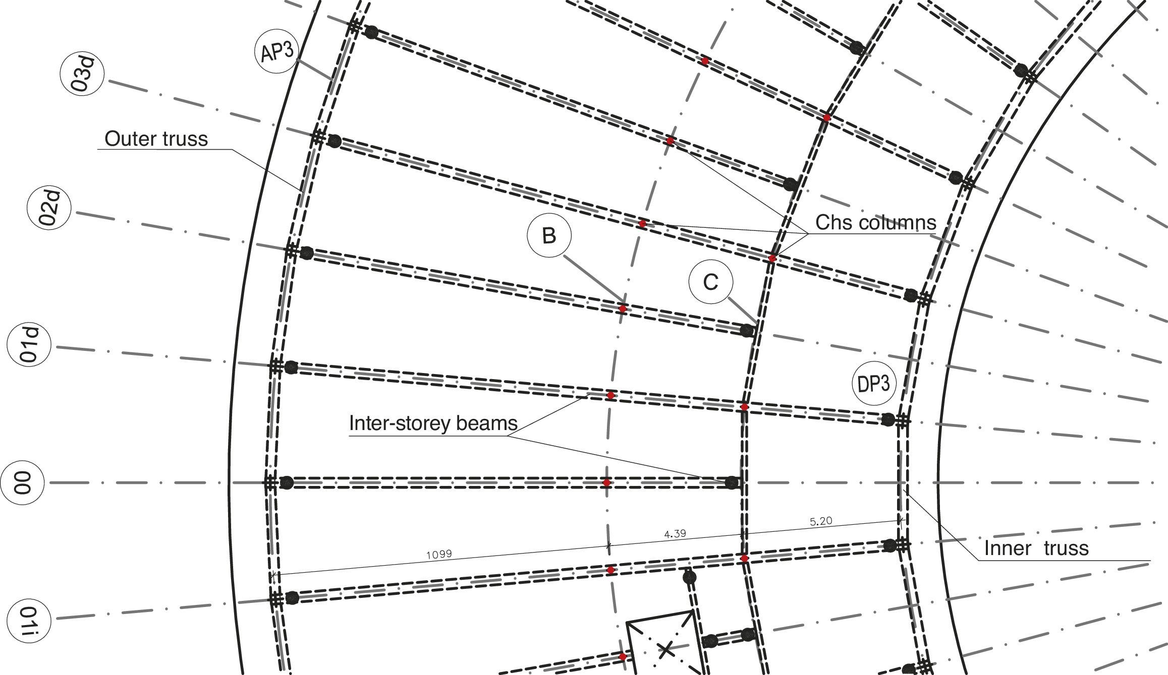
The composite beams forming part of the structural slabs were likewise arranged radially in a manner to concur with the truss nodes. The inner circular axis was designed as a continuous beam on which every other radial beam rests, to make the transition from the angular modulation of the outer to that of the inner truss (Fig. 10).

The use of corrugated steel decking was ruled out for the concrete slabs, given that the standard 4m distance between radial beams, would have called for very thick decking, or the use of intermediate joists. Moreover, the decking would have had to be cut into pseudo-circular sectors of variable dimensions depending on the zone. The additional on-site difficulties that would have entailed rendered this option clearly unsuitable.
3.6Sloped structural bottom and roof slabsThese structural slabs were engineered to serve a triple purpose: first, to enclose the top and bottom of the building; second, to have sufficient bearing capacity to withstand the loads received from the inner columns in the cantilever (that cannot connect to the foundations); and third, further to the initial ‘megastructure’ concept, to form the flanges of the huge box girder that constitutes the building's cantilever.
The first two purposes (building enclosure, base for inner columns) called for a powerful radial structure able to transfer stress to the side trusses. The third, in contrast, required a structure able to effectively assume the circumferential axial and shear stresses. For that reason, the chosen solution was, as in the inter-storey floors, a composite structural slab, although with double the depth (500–600mm) of the built-up, rolled steel beams. The concrete slab was increased to a thickness of 20cm (Fig. 11).
3.7Below-grade structures
The elements described in the preceding sections constitute the above-grade structure that rises over a concrete base housing a basement and an entrance storey. This base was designed to contain all the members listed below, needed to enable the ‘megastructure’ to transfer the building stresses to the soil (Fig. 12):
- •
bearing diaphragms for trusses: 20m long, 60cm thick flat members located underneath the points where the trusses rest on the base that receive the major share of the stresses on the fixed end of the cantilever;
- •
truss columns and tie beam: concrete portal frame located downstream of the diaphragms that receives the (much less intense) stresses generated by the truss anchorage at the rear of the building, in which the 1.00m (h)×0.60m (b) beam rests on 0.45m diameter circular columns;
- •
wall beam: 40cm thick member positioned at the end of the bottom structural slab (which for reasons of functionality is not directly connected to the foundation as would be called for in orthodox design from the perspective of how the ‘megastructure’ should work) which conveys its vertical reaction to the side diaphragms via shell mechanisms.
, and columns and tie beam (in blue).")
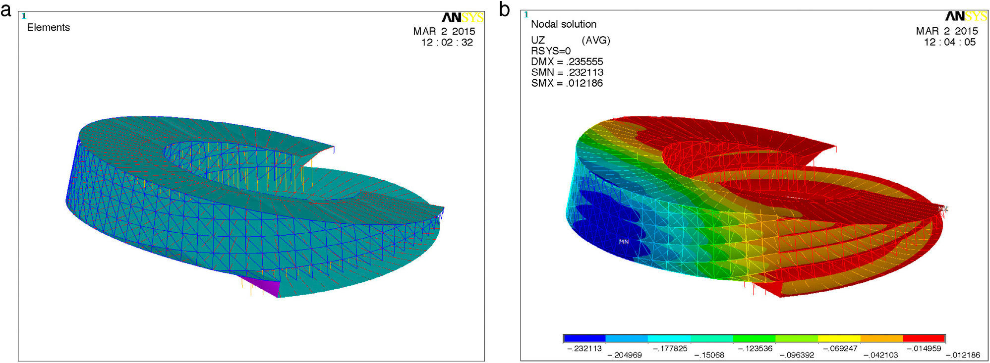
The building was analysed by stages. First, a conceptual numerical model was developed in which practically all the specific local features (service shafts, lifts, balconies) were omitted, to determine the contribution of the main elements described in the preceding section to the overall bearing capacity. This initial approach to the building behaviour supported the subsequent decision-making, and influenced the still incipient architectural design in order to optimise structural performance and enhance ‘tensibility’ (Fig. 13).
 and deflection under permanent loads (right).")
The main conclusions drawn from the conceptual model were the following.
- •
The outer and inner trusses constitute the structure's primary strength mechanism, and given their great depth, they are not only able to convey the shear on the megastructure, but also to withstand a substantial share of the bending stress.
- •
Overall bending stress is less intense on the sloped structural slabs than might be expected from the coupled tensile/compressive forces borne, due in particular to their high depth/span ratio. Consequently, most of the cantilever can be regarded as a D-region. Similarly, the lack of any consistent axial stress in these structural slabs at their connection with the base limits their ability to act as box girder flanges.
- •
Nonetheless, these slabs play a substantial structural role in keeping with two mechanisms:
- ∘
as tensile and compressive flanges, which is perceptible when their edges are longitudinally stressed or their transverse modulus of deformation is varied;
- ∘
as chords in the circumferential Viereendel trusses, formed by the bending stress on the rings of columns and the structural slabs themselves.
- ∘
- •
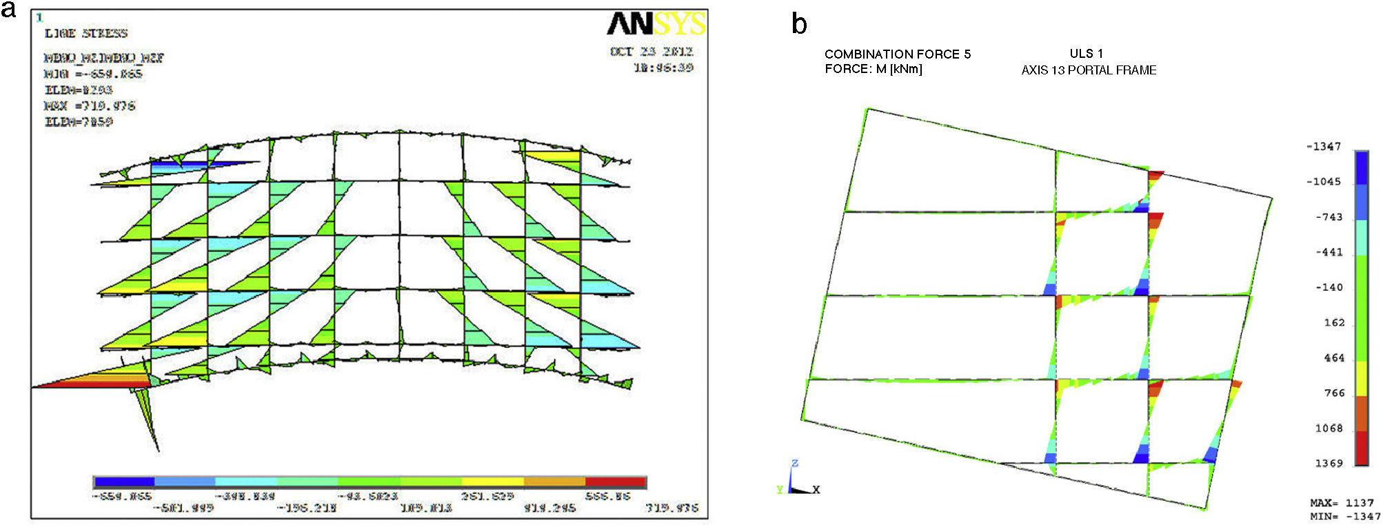
A Vieerendel truss-like mechanism arises in the radial planes where the inter-storey composite beams and the columns form flexible diaphragms. These elements help counter the distortion in the box girder section, bearing axial and bending stresses, and inducing sizeable bending in the girder components (Fig. 14).
 and a radial plane (right).")
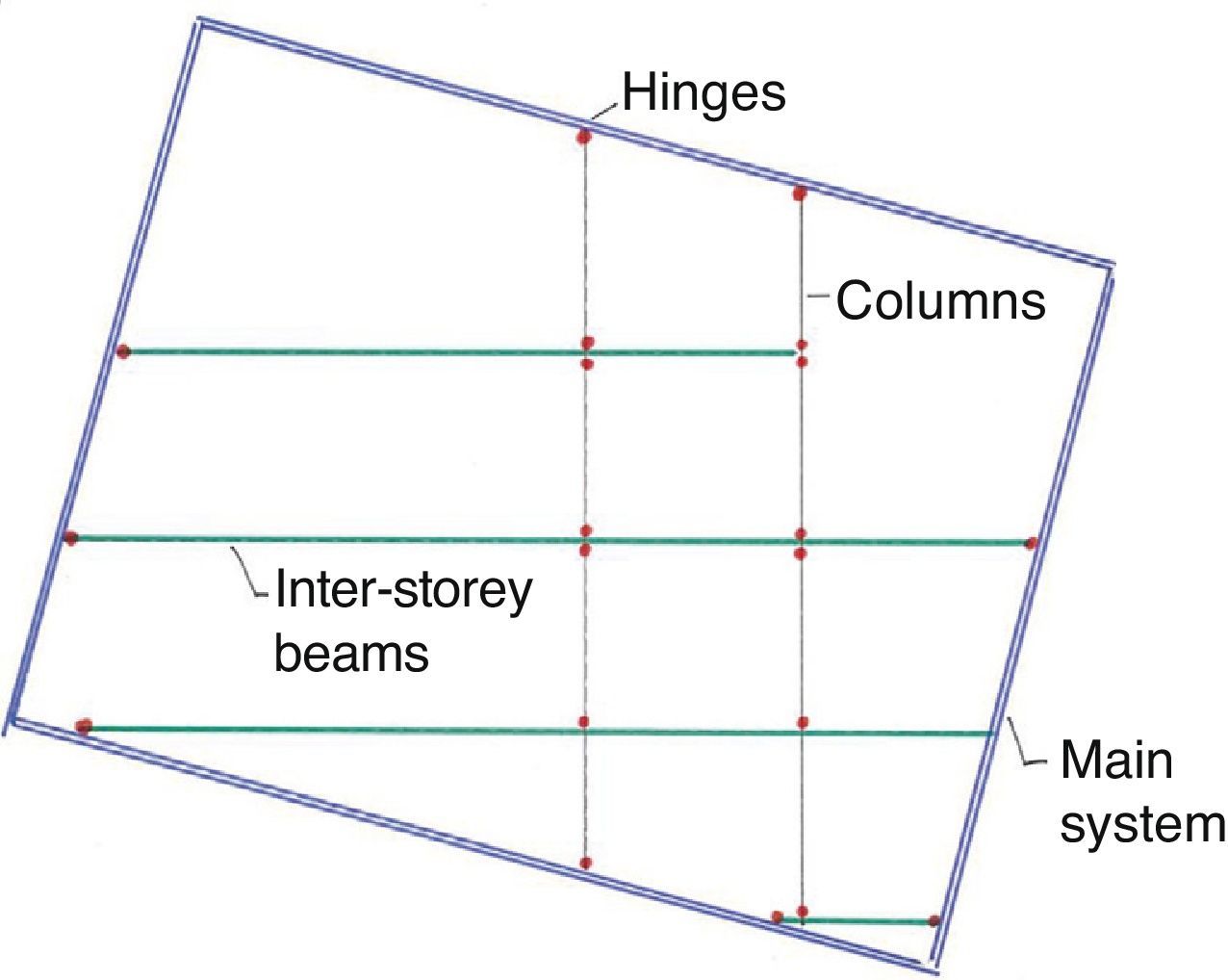
The detailed iterative model, developed with the precise geometry and actual conditions required to adjust component dimensions, revealed factors that failed to surface in the conceptual analysis. The most prominent of these was that, while the initially chosen alternative envisaged participation by most of the elements in overall strength, the reality of dimensioning made it clear that the excessive parasitic stresses generated in such a solution, would lead to a vicious circle in which raising stiffness would entail a concomitant rise in stress. As a result, the main structure was clearly dissociated from the secondary structures by providing for the following hinges (Fig. 15):
- •
between the inter-storey beams and the trusses and the C axis beam
- •
between columns and beams
- •
in certain beams, where system stiffness would undergo an abrupt change (leverage).

A highly statically overdeterminate structure, in which many elements contribute to structural stability, not only in their own local sub-systems but also in the global operation, called for a nimble numerical model able to accommodate substantial iteration. That, in turn, necessitated stringent control of the input and highly skilled analysis of the output.
Improvements or specific adaptations in the ANSYS finite element-based proprietary software were developed for this project.
- •
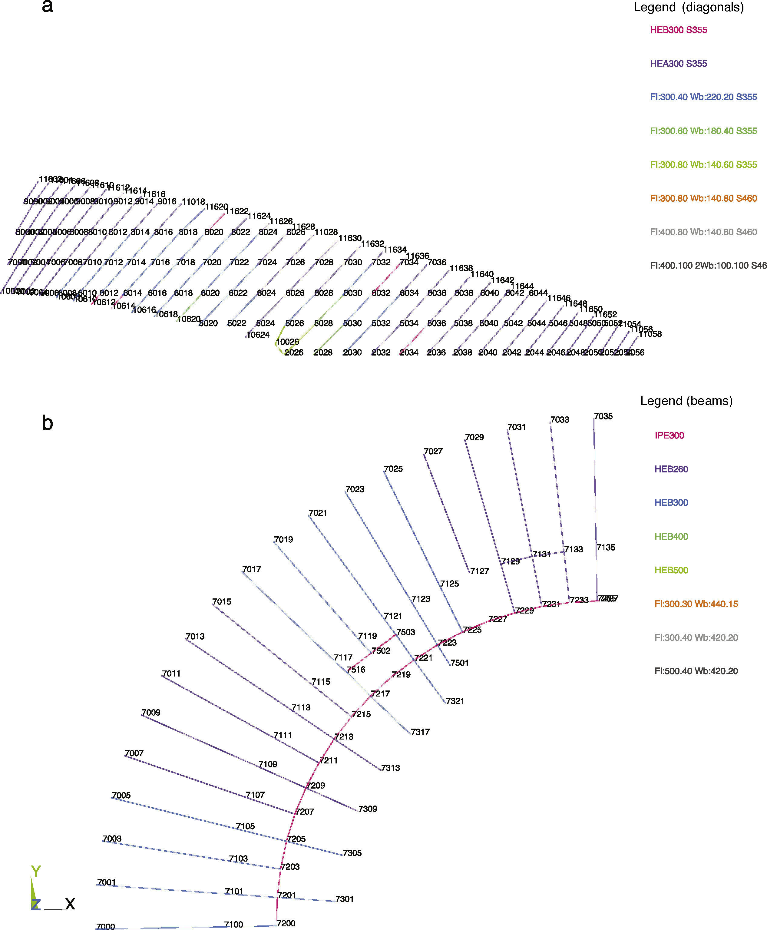
Beam, column and truss graphics: plan or elevation views of the profiles defined were depicted by creating representation groups, and colours were assigned to the beam or bar types to be able to readily verify the data entered in the model (Fig. 16).
- •
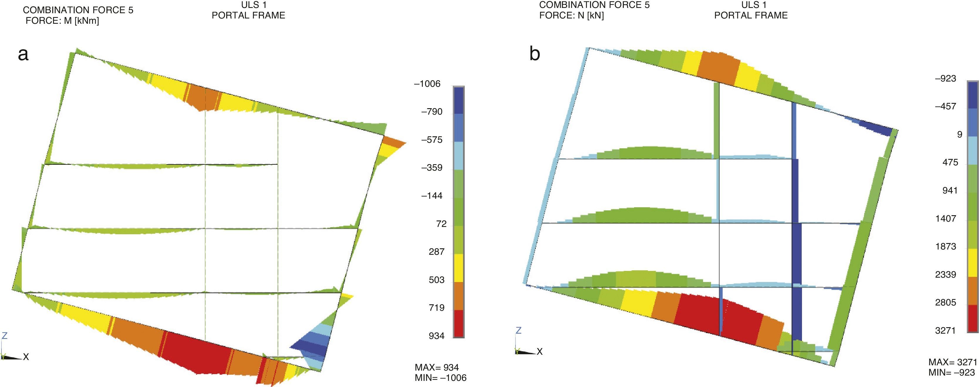
Graphic outputs for radial plane stresses: the main stresses (axial, bending and shear) on the radial planes were represented to quickly and intuitively visualise component behaviour, and to detect modelling errors or questions not envisaged in the initial calculations (Fig. 17).
- •
Verification of composite beams: the structural slabs were modelled taking the slabs as shell elements and the suspended steel beams as beam elements. Verification of the composite section consequently called for compounding the stresses on both elements, taking into consideration the variability of the effective flange width of the slab, due to the inter-storey height and specifics such as openings and header beams. With a view to expediting these calculations, a parametric study was conducted to confirm the following hypothesis: verifying that the steel section based on the stresses on the beam element alone lies on the side of safety with respect to verifying the composite section based on the compound stresses [10].
, and beams in storey 3, bottom (b).")
 and axial forces (right).")
The parametric study consisted in differentiating between two shapes (IPE300 and HEB500), assuming a (design-typical) 15-cm slab, and effective flange widths ranging from 25cm to 3m, and testing four stress cases (positive and negative moments, separate from or associated with same sign axial stresses). The stresses to be borne by the steel section were calculated from the performance of the section as a whole through elastic failure; and the safety coefficients found with the two verifications (composite section with compound stresses; steel section with simple stresses) were compared. The results showed that section verification based on simple stresses lay on the safety side in all but one of the cases: pure negative bending stress (due to the variation in the centre of gravity of the section as a result of slab cracking). The solution adopted to cover this situation was to raise the negative stresses by the established factor of 1.15, which was, moreover, the mean of the situations in which simplified verification delivered results on the unsafe side. The outcome of conducting this parametric study, then, was that the building's one thousand composite beams could be readily and accurately verified.
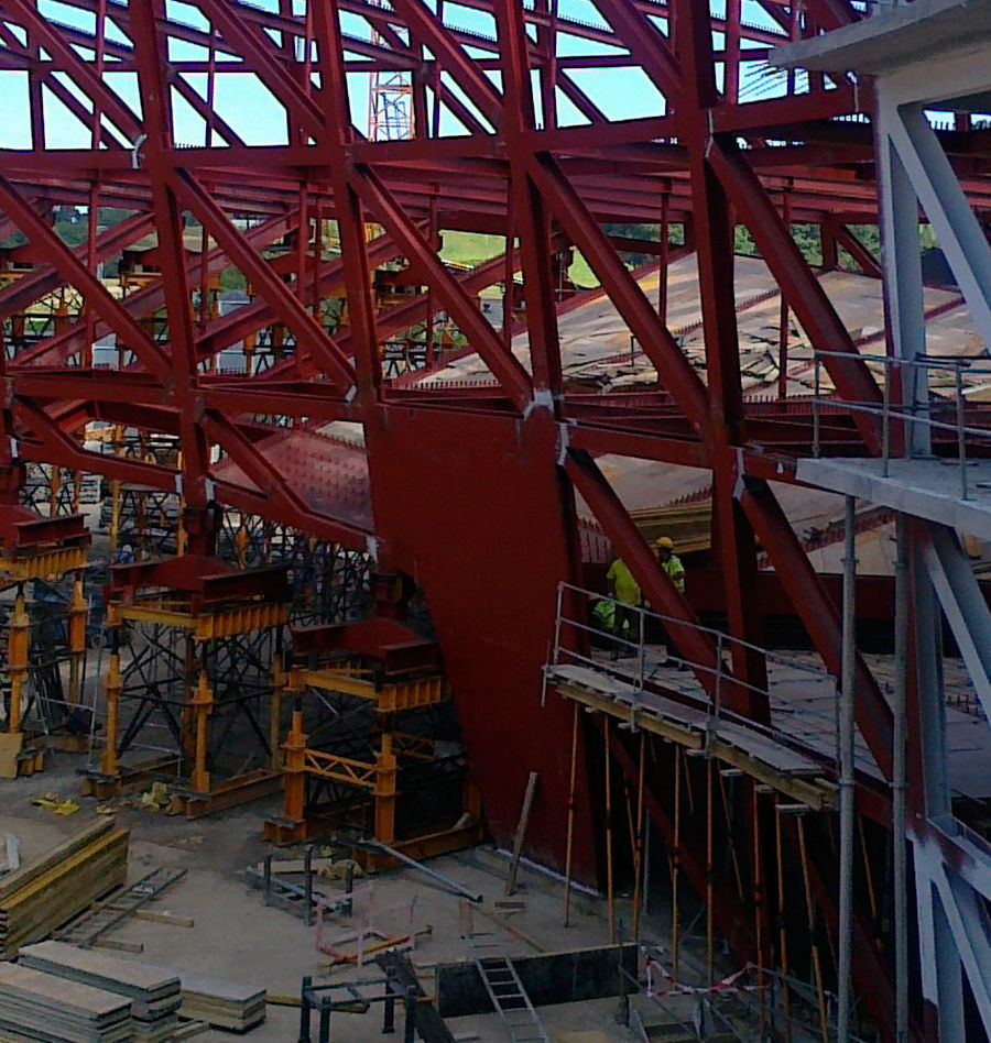
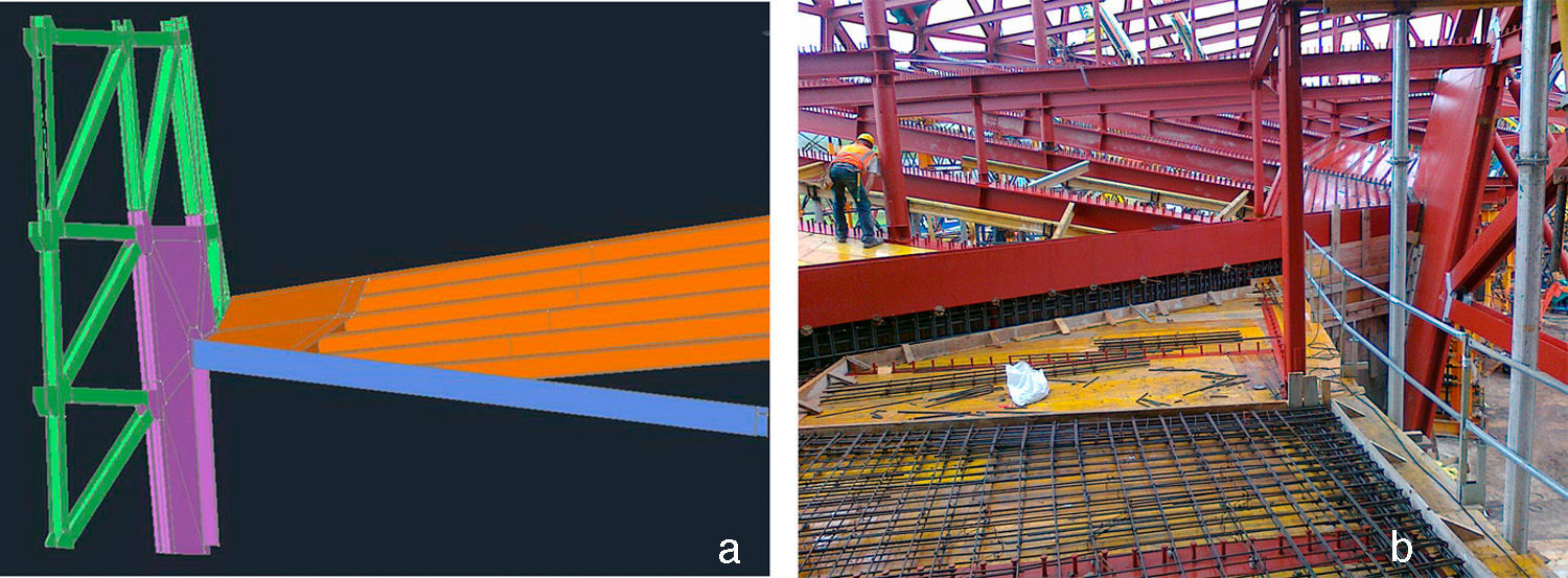
4.3Singular pointsShape adjustment iterations revealed that loading the shapes springing from the bearing diaphragms was a particularly concentrated and statically determinate process (scantly dependent upon variations in stiffness that could be enlisted for more diffuse loading). For that, the inclusion of stronger members able to receive the concomitant axial stresses was needed. Those reinforcing elements, which served to transition between the massive bearing diaphragm structure and the single line truss components, were no more than sheet metal panels filling in the inter-shape gaps and receiving some of their load (Fig. 18).

Similarly, loading was found to be particularly abrupt at the corner formed by the bottom slab, the inner truss, and the wall beam, where the stresses on the 20cm concrete slab would amount to 60MPa. The solution chosen was to reinforce the area with sheet metal bolted to the concrete, and to place a steel tie on the wall beam (Fig. 19).
 and construction photograph (right).")
Likewise, the uprights closest to the cantilever were observed to be subjected to very high axial compressive stress, generating much greater stress on the top of the bearing diaphragms than could be borne by the concrete. Here the option adopted was to embed shapes which, via a connection distributed along their entire length, afforded more diffuse concrete loading.
4.4Standard connectionsThe construction design listed the basic criteria governing the standard connections, leaving geometric development to the metal works plant. The main nodes are listed below:
- •
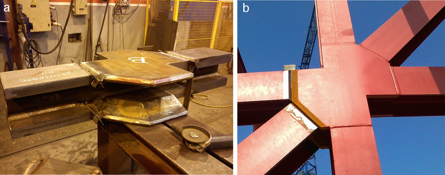
Standard truss node: gusset receiving up to six bars whose thickness was determined as the dimension needed to receive the axial stress from the webs and flanges of the largest bar received. These doubly folded nodes were to accommodate the difference in the semi-angle between two consecutive radial axes. The folds were reinforced with stiffeners to distribute the deviation forces (Fig. 20).
- •
Beam-column node: partially hinged node designed to lower flexural stiffness substantially, and induce the appearance of a plastic hinge, indispensable to dissociate the primary from the secondary systems and minimise the appearance of parasitic loads.
- •
Node between horizontal and sloped beams: as above, some partial hinging was sought between the two elements to avoid secondary moments.
 and after on-site assembly (right).")
Early into the design phase, a need was acknowledged to position nearly all the structural members in radial and concentric vertical planes: i.e., truss uprights, inter-storey (horizontal) and sloped beams and inner columns were to be coplanar. That assumption greatly simplified stake-out and assembly, the design of coplanar nodes and the introduction of camber in the cantilever sections.
Moreover, many particularities were detected during the development of a precise geometric model for the building, some of which had been envisaged while others were revealed by three-dimensional modelling:
- •
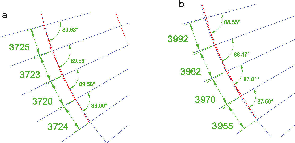
Although the storeys are elliptical, all the elements were designed to be rectilinear. That in turn entailed a translation of the centre of each storey, whereby cutting a cross-section in the ellipses through the bundle of axes resulted in module variability and differences in element dimensions (Fig. 21).
- •
The model showed that as the uprights are not generatrices of the cylinder, they formed a polygonal line. To facilitate construction, the straight line connecting their end points was taken as the basis for rectification.
- •
As a result of the foregoing and the fact that the design of the storeys resulted in ellipses whose centres were not aligned, the radial axis lines were not perpendicular to the contour. Given the aforementioned decision to use straight uprights and contain the structure in general in radial planes, the sides of the uprights were not contained in the surfaces parallel to the ellipse. Consequently, the angles of the folds on the gussets likewise mentioned above were not symmetrical, and indeed in some extreme cases one of the folds absorbed the entire angle, leaving the other edge straight.
- •
As the slanted and horizontal floor slabs meet at a fairly small angle (15°), the horizontal area formed at the overlap is large. These overlaps were defined during the engineering phase as the abutment between the top sides of the slabs. Given the finite size of the elements, however, the model showed that the actual connection between the steel components could deviate considerably from the theoretical intersection, necessitating specific revisions of each zone to adapt the design and calculations to geometric realities.
 and first (right) storeys.")
The tight construction schedule imposed by the building's owner called for optimising assembly procedures to expedite construction. Some of the areas where the metal works plant and the design engineer worked together are described below.
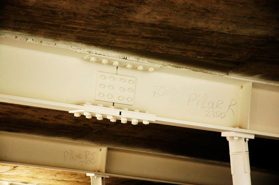
First, a specific study of each node type led to the adoption of a bolted solution in a fair percentage of the nodes, including: the vast majority of inter-beam nodes, both hinged and restrained, (barring the ones requiring welding, for reasons of capacity), all the column-beam nodes, and the inter-storey beam-truss nodes (Fig. 22).

The joints between truss elements were studied in great detail in light of their impact on manufacturing and assembly times. While the original continuous welding procedure for the truss nodes was maintained (for reasons of aesthetics and capacity both), a great deal of effort was put into optimising weld thickness, thanks to which 70% could be switched from full to partial penetration welds. The number of truss nodes requiring stiffeners was also optimised, and were conducted verifications of the sections in which the cope holes required to accommodate the thickness reduced the effective section of the web to the point of compromising its integrity. Slender platbands were designed to be placed over the welds to strengthen the axial capacity of the elements.
In addition, and perhaps more importantly, given the optimality of the solution, an exhaustive weld inspection plan was implemented by an outside quality control company. Only a very small percentage of the large sample inspected proved to be defective.
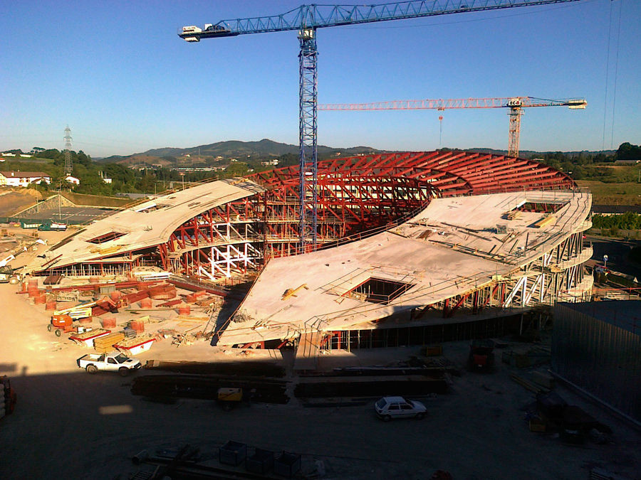
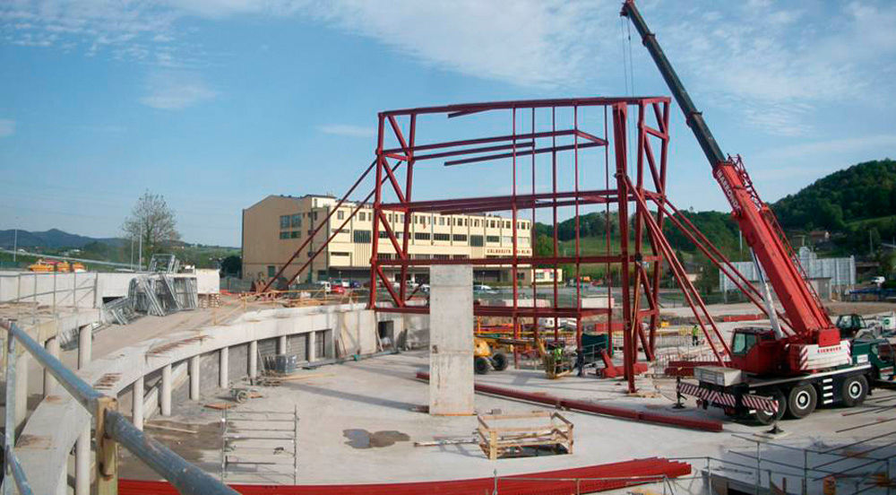
5.3AssemblyThe assembly procedure adopted by the metal works plant consisted in positioning alternating truss panels. Each panel, comprised two uprights and all their intermediate elements, was shipped from the plant fully assembled, along with separate elements to be placed between any two adjacent panels (Fig. 23). As the inner skeleton was erected by fully assembled sectors, the structure grew radially rather than vertically. As a result, construction could proceed from the perpendicular axis of symmetry in four work sections: two towards the front end of the cantilever and two towards the rear.

Provisional propping was needed during the hoisting operation to ensure the transverse stability of the panels in the radial direction, and to receive the horizontal component of the load generated by the slope on these components (Fig. 24).

However, in a radial cross-section, given the slope on the cylinder, both trusses sloped in the same direction. Consequently, in the early stages of assembly, the erection of the inner structure did not suffice to stabilise the whole assembly. A protocol for removing the props was developed to prevent failure due to instability of the structure as a whole, while also reducing the assembly tolerance to offset the strain on the structure resulting from its deviation from the vertical.
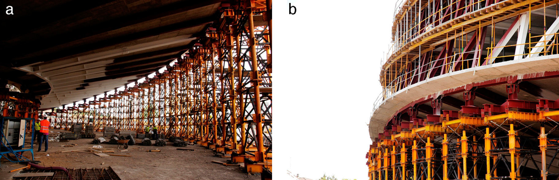
5.4Prop removalIn the cantilevered area the entire steel structure was assembled on shoring towers (Fig. 25). Two main unknowns were addressed with a view to ensuring safe prop removal conditions:
- •
appraisal of the initial reactions;
- •
implementation of a process that would not place excessive loads on the provisional towers, the foundations built specifically for them or the truss bars themselves, which in the front areas were very slender in light of the small stress to be ultimately borne.

A sensitivity analysis of the parameters affecting the distribution of reactions was conducted to appraise the reactions and expected strain as precisely as possible. The findings showed that significant differences could arise depending on:
- •
the value of the G-modulus of the transverse strain adopted;
- •
the off-sets assumed for the truss bars;
- •
the axial flexibility of the shoring towers;
- •
construction progress.
In contrast, the early age modulus of elasticity was found to have a scant impact, inasmuch as fairly insignificant sections of slab would be cast a short time prior to prop removal.
On the grounds of this preliminary analysis, an initial model was established whose most prominent characteristic was the adoption of a variable distribution for the G-modulus depending on the areas subjected to the greatest shear stress. The initial reactions to prop removal were generated from the initial model. At the same time, the allowable reaction limits were obtained, determined primarily on the grounds of the bearing capacity of the foundations built for the shoring towers.
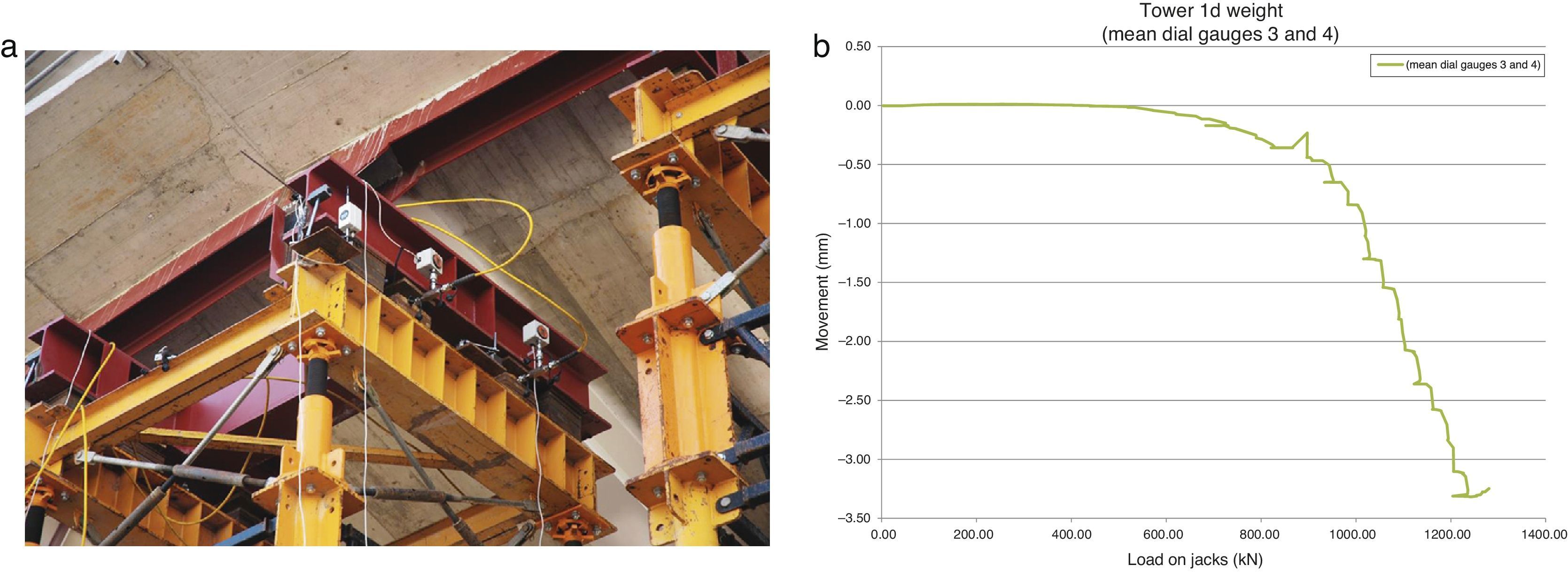
When 6 of the total 33 columns were weighed to validate the theoretical reactions estimated, the results were somewhat scattered. Weighing was conducted in much the same way as in works to widen the spans in flyovers [11], using dial gauges to measure the movement in the structure when subjected to pressure from the hydraulic jacking system. The graph in Figure 26 plots weight against movement (F–d curve). Note that, when the load borne by the tower was reached, the slope on the F–d curve varied drastically.
; F–d diagram plotted with readings taken during the operation (right).")
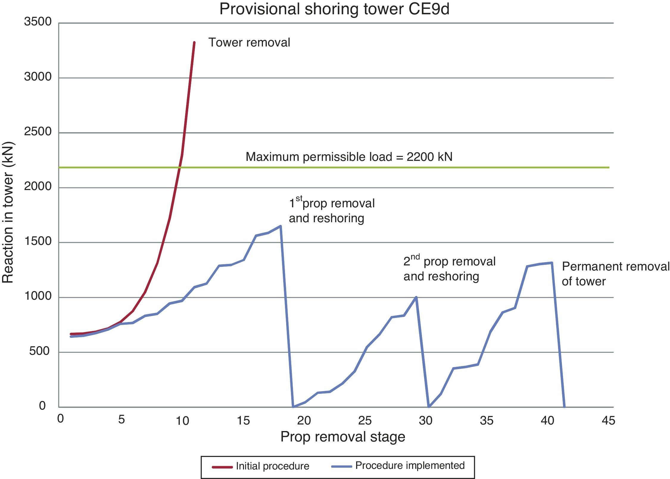
After the theoretical reactions were validated, prop removal adjustments were undertaken. From the outset, it was obvious that the procedure designed would have to provide for the gradual descent (and loading) of the structure, in which the shoring towers would have to afford some degree of support. The large number of provisional towers (33 in all) and the small overloads that could be assumed by each and its foundations (around 2.5 times the initial reaction) ruled out the simple gradual removal of the towers.
The alternative consisting in the partial lowering of the props was likewise unworkable, given the stiffness of the structure the expected descent after the release of a support was always less than 5mm, a magnitude extremely difficult to control in practice.
The solution ultimately stemmed from the observation that when any single tower was removed, the load was distributed among the rest in keeping with the stiffness of the adjacent towers. Since the tower height declined progressively from the cantilever to the springing line, elements closest to the latter assumed higher loads, although the load transferred to the supports at the outermost end of the cantilever was not negligible.
In light of the foregoing, a system was devised in which the existing reaction could be relaxed with load transfer and reshoring operations, and the loads gradually conveyed to the permanent supports. Two load transfer and reshoring operations were conducted for each provisional support prior to its permanent removal, as depicted in Fig. 27. In addition, the three groups of operations (two load transfers, and reshorings, and one permanent prop removal) were overlapped, to prevent the reactions from generating an excessive rebound in the direction of the cantilever.

Prop removal, conducted as described above, was monitored throughout by measuring five additional parameters:
- •
the reaction in the jacks on the tower to be withdrawn as soon as the chocks could be moved and immediately after they were released;
- •
the distance the structure descended after the jacks were relaxed;
- •
the chocks removed when the structure was re-shored;
- •
weight of a tower adjacent to the tower to be removed, before and after release of the latter, to determine the load increase;
- •
topographic data of the structure at the end of each day.
As would be expected, the scatter found in the measurements of these five parameters was not negligible. Nonetheless, the movements in the tower released provided a good fit to the initial estimate, while the reaction and topographic data were somewhat more widely scattered. After the operations, the cumulative descent at the high point of the cantilever came to 63mm, i.e., less than 10% of the theoretical value.
These prop removal operations marked final completion of the structure, just 15 months after the preliminary studies had begun [12].
6ConclusionsThe construction of a new corporate headquarters called for the design of an iconic building recognisable by employees, customers, visitors and society at large. That objective was indisputably met by the architectural team (Figs. 28 and 29). The structural challenges stemming from a design with visual impact must be confronted with criteria of structural efficiency, constructional rationality, and minimal effect on architectural functionality. By applying conceits such as ‘megastructure’ as in this project, major structural challenges can be addressed with the intelligent use of the potential and resources deriving from the architectural form. Thanks to close cooperation among all project participants during the conceptual design, development, and construction phases, highly efficient use was made of all the available resources to erect the building without forfeiting a single line of its unique design.
List of participants

Owner: ORONA;
Architectural design: ORONA and LKS Ingeniería;
Structure: MC2 Estudio de ingeniería;
Construction: Mariezcurrena (concrete structures), URSSA (steel structures);
Weighing, prop removal control: INTEMAC and BETAZUL.