


In this paper, a fibre beam model previously developed by the authors for the nonlinear analysis of strengthened elements, including the effects of shear, is used to predict the response of reinforced concrete (RC) beams strengthened in shear with fibre reinforced polymers (FRP) sheets. This model has been extended not only for wrapped configurations but also for debonding failure in order to allow for its application to beams strengthened with U-shaped and side-bonded configurations. When simulating existing experimental tests, the model reproduces, with reasonable accuracy the behavior of the beams, being then a useful tool for practical engineering.
En este artículo se presenta la extensión de un modelo de filamentos y barras para el análisis no lineal de elementos reforzados externamente a cortante con laminados de polímeros reforzados con fibras, teniendo en cuenta los efectos del cortante. Este modelo se ha extendido no solo para configuraciones que envuelven de forma completa la sección con el laminado de polímeros reforzados con fibras, sino también para los casos en que se puede producir desprendimiento prematuro del laminado, para permitir su aplicación en vigas reforzadas en U o con laminados adheridos en las almas. Al simular ensayos experimentales existentes, el modelo reproduce, con una exactitud razonable, el comportamiento de las vigas reforzadas y, por tanto, es una herramienta útil para la ingeniería práctica.
The shear strengthening by means of FRP sheets or laminates can be performed in different configurations: (a) sheets fully wrapping the cross-section (wrapped); (b) sheets or L-shaped laminates bonded on the lateral sides and the bottom surface of the beam (U-shaped); and (c) sheets or laminates bonded in the lateral sides of the cross-section (side-bonded). The sheets and laminates can be bonded in a continuous or discontinuous manner.
In the case of wrapped configurations, the shear failure is accompanied by FRP rupture or the FRP system can fail due to the rupture of the fibres at the round corner of the section. In U-shaped or side-bonded configurations, the FRP may debond before reaching its ultimate capacity.
A fibre beam model developed by the authors for the nonlinear analysis of RC and strengthened elements including the effects of shear [1–4] has been improved to account for strengthening by means of FRP sheets. The model has been validated in [5,6] through the analysis of RC beams strengthened in shear with FRP sheets involving different configurations by means of the modelization or the experimental campaign of Alzate [7], Khalifa and Nanni [8], and Matthys [9]. The model reproduces, with good accuracy, the experimental failure loads, the load-deflection behavior and the strains in stirrups and FRP with increasing load until failure. It also reflects the load-sharing between inner transversal steel reinforcement and EB FRP before and after premature debonding failure. This achievement is important due to its simplicity and computational speed to be applied at true scale structural analysis, making it an attractive tool for practical engineering. This paper briefly explains the model and shows some of the results of their application to simulate some existing experimental results.
2Fibre beam model2.1Fundamentals of the modelThis model is based on a flexural fibre beam model [10] which considers the interaction axial force – shear – bending moment (N-V-M) and uses a displacement-based FE formulation for the nonlinear phased analysis of concrete frame structures. The detailed formulation and validation of the 1D model with shear critical benchmarks was presented elsewhere [1–4]. Only a brief description of the fundamentals of the model is presented here.
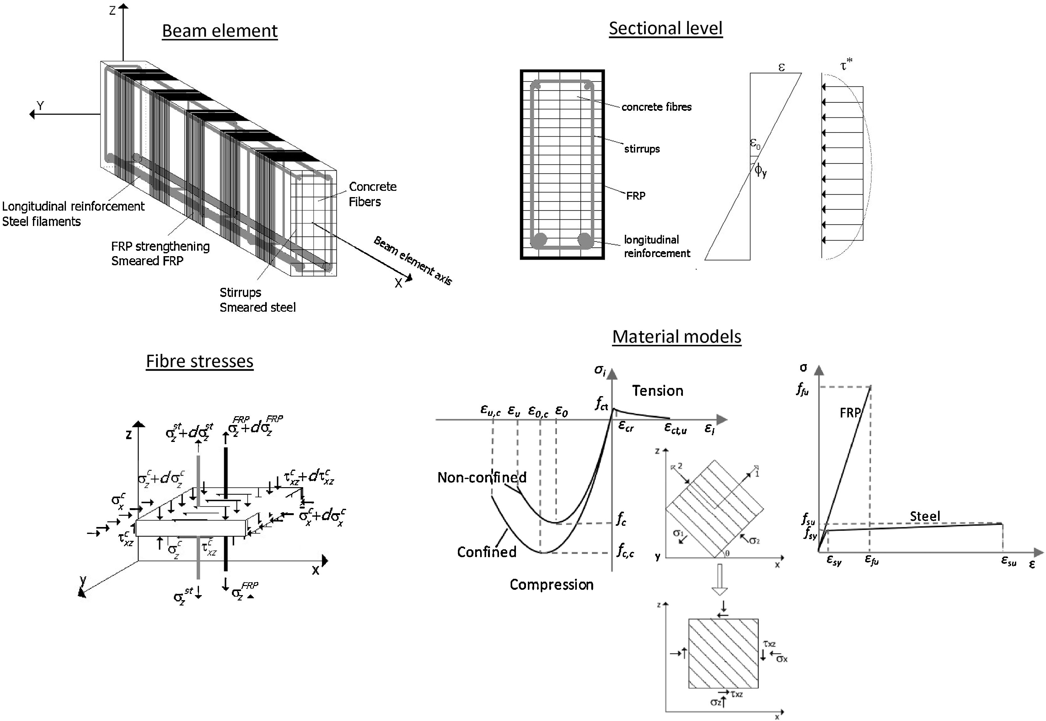
Fig. 1 presents the general characteristics of the model for different levels of analysis: element, section, fibre and material. Regarding the element level, the model is based on the Timoshenko beam theory with the cross-section discretized into fibres, the longitudinal reinforcement simulated by means of filaments and transversal reinforcement considered smeared in concrete. At the sectional level, a shear-sensitive model accounts for the nonlinear force interaction (N-V-M). The plane-section theory, that allows determining the longitudinal strains at each fibre as a function of the generalized strains of the section, is coupled with a constant shear stress constraint along the cross-section. Filaments of longitudinal reinforcement are only submitted to axial strains and stresses, following the plane section theory. Transverse reinforcement (internal steel stirrups and/or EB FRP) is accounted through its volumetric ratio ρst and is submitted to axial stresses σzst. Compatibility requirements impose that the vertical strain ¿z in concrete is equal to the strain in the transverse reinforcement. The computed shear stresses τxz must equate the imposed shear stresses given by the fixed stress constraint τ* of the sectional hypothesis. By guaranteeing these two requirements, the vertical axial strain ¿z and shear strain γxz of each fibre are outputted. This determination is not linear and an iterative procedure within the fibre level is needed.

Pertaining to the material simulation, a smeared and rotating crack approach is considered for concrete. Then, the cracked concrete is simulated as a continuous material with orthotropic nonlinear uniaxial equivalent characteristics considering full rotation of cracks. The Hognestad parabola is considered for concrete in compression. Lateral effects of softening [11] and strength enhancement [12] factors are included. When FRP strengthening is placed by means of a wrapped configuration, the increment of both peak strength and ultimate strain of concrete due to the confinement action is considered through the model of Spoelstra and Monti [13]. A linear response is assumed for uncracked concrete in tension and a tension stiffening curve [14] is considered for the remaining stresses in the cracked stage. Longitudinal and transverse reinforcements (steel and FRP) are under 1D stress–strain states determined through linear uniaxial constitutive equations, with kinematic hardening for steel. Perfect bond is assumed between the concrete and the steel reinforcement.
2.2Debonding failureAs experimentally observed in existing experimental programmes, U-shaped and side-bonded configurations of FRP usually fail due to debonding after the formation of a critical shear crack. For shear strengthening, the debonding failure initiates once the shear critical crack opens. Then, the laminate debonds if the FRP bonded length from the shear crack to the laminate end is not enough to anchor or transfer the tensile force acting on the FRP. In the side-bonded case, debonding can be observed at both sides of the critical shear crack. In the U-shaped case, debonding occurs in the upper side of the shear crack.
The debonding failure approach implemented in the present model is that proposed by Oller et al. [15]. This model was originally developed to predict debonding failure at the laminate end in beams externally strengthened by FRP in bending. This formulation can also be applied when predicting debonding for FRP shear strengthening. For U-shaped configurations, the bonded length Lb of each strip is the bonded length above the critical shear crack. For side-bonded configurations, the bonded length of each strip is the minimum length of the laminate above or below the critical shear crack.
The maximum transferred force Fmax along the bonded length Lb, can be expressed as [15]:
where bf is the FRP width; tf is the FRP thickness; Ef is the FRP modulus of elasticity; τLM is the maximum shear stress at the interface given by Eq. (3); Gf is the fracture energy or energy by unit area necessary to separate the laminate from the support given by Eq. (4). Units are in N and mm.where fcm is the mean value of concrete compressive strength; fctm is the mean value of concrete tensile strength; CτLM is a constant equal to 0.87; and CF is a constant equal to 0.35.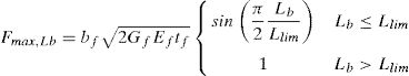
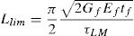
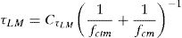
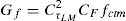
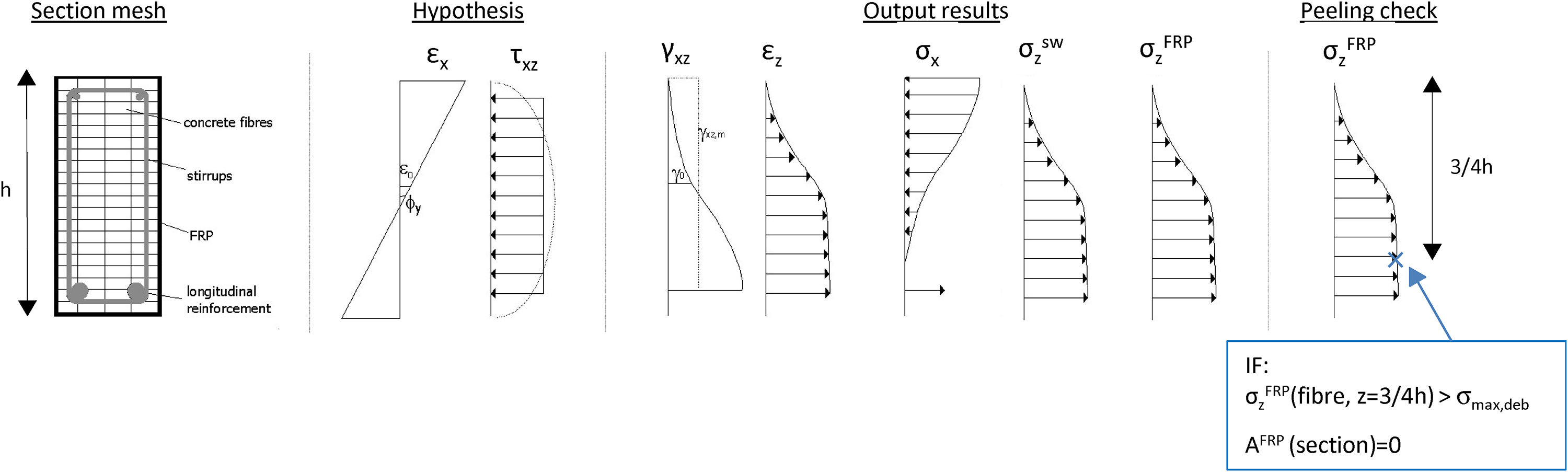
Fig. 2 summarizes the input hypothesis considered in the sectional model, the output results and the criteria for checking FRP debonding failure. The gradients of vertical stresses between the border and the shear critical fibre are computed to be compared with the maximum transfer force. The shear critical fibre is considered to be located at 3/4·h being h the height of the cross section. The stress at this fibre is considered the critical tensile stress σzFRP (z=3/4·h). This criterion is a consequence of the basic hypothesis of the model, resulting into higher shear strains and higher vertical strains in the more cracked areas [4]. Since the vertical stress in the border is null, the gradient is equal to the tensile stress in the critical fibre. The critical stress in the FRP, σzFRP (z=3/4·h), is compared with the maximum vertical stress that can be transferred to the FRP, σmax,deb, given by Eq. (5), that corresponds to the maximum transferred force Fmax,Lb. When the stresses σzFRP in the FRP laminate in the critical fibre reach the maximum allowed stress that can be transferred by bonding mechanism, the area of the FRP reinforcement of that cross-section is set to zero, and the analysis may continue with redistribution of forces in the remaining steel stirrups and FRP sheets in other cross sections.
3Numerical analysis of the experimental programme of Alzate [7]

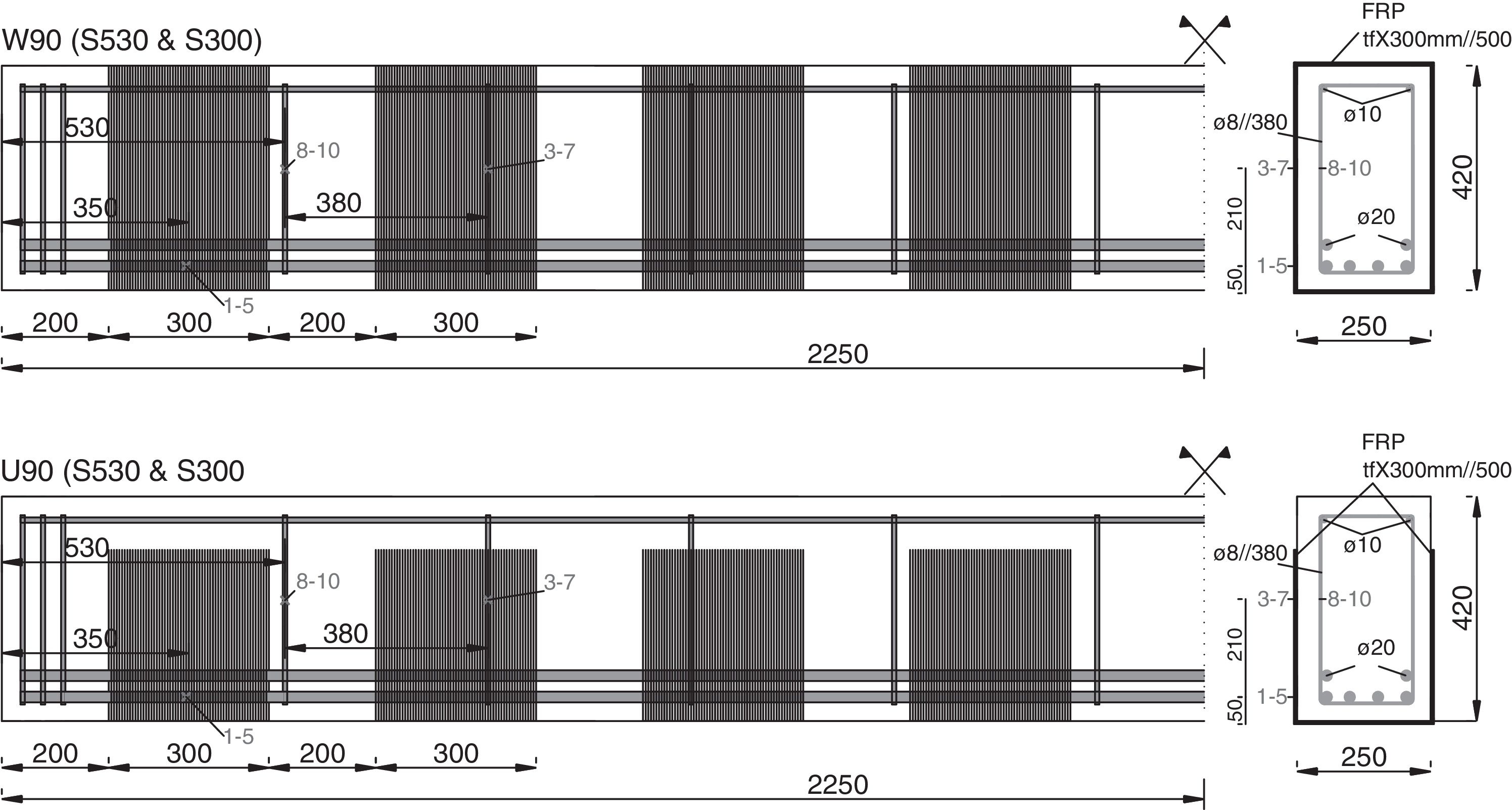
An experimental programme on FRP-shear strengthened RC beams was carried out by Alzate [7] with the purpose of studying the contribution of FRP to the shear resistance of RC elements. The beams were simply supported, 4.5m long and with a rectangular cross section of 0.42m height and 0.25m width. A RC beam critical to shear (control beam) was strengthened with different solutions of FRP in terms of configuration and quantity and tested until failure. From the set of beams tested in the experimental campaign, this paper presents the numerical simulation of some of the beams strengthened in shear with vertical FRP strips. A concentrated load was applied at a distance of 3 times the total depth (a=3h=1.26m) from the support. Geometry, internal reinforcement and strengthening configurations of the specimens are represented in Fig. 3.
![Geometry, reinforcement, strengthening configurations, and instrumentation of the beams tested by Alzate [7].](https://static.elsevier.es/multimedia/04395689/0000006900000285/v1_201809230636/S0439568917300372/v1_201809230636/en/main.assets/gr3.jpeg?xkr=ue/ImdikoIMrsJoerZ+w997EogCnBdOOD93cPFbanNcmaQhbHYBdp0SiDFRxASFlWq9rl9/0Ykb2bSKK7DB2WAc9i5Niuu4K+soZVPiMMcrsxVXOLaBYSj51FAhz6IDlPgqaUnkqpx2AbwflG5IXsza/z2BQ0XppPoDkiw6SuPq/3hI/2LV+ZD4UqfKwiY40XFJ1rAusiZEf+B8YkJHloCcVaG+yXn9YP2BK7Ly7RbrIl39kS5lDpBwgHLM5z86DJGqPXB9AawnWomHbnfrWISZA2tdilS0AjJhnimhLM+c= "Geometry, reinforcement, strengthening configurations, and instrumentation of the beams tested by Alzate [7].")
Geometry, reinforcement, strengthening configurations, and instrumentation of the beams tested by Alzate [7].
Beams were reinforced with FRP sheets of 300mm width presenting two different thicknesses – S530 represent unidirectional fibres (530g/m2) with dry fibre thicknesses of 0.293mm and S330 represent unidirectional fibres (300g/m2) with dry fibre thicknesses of 0.176mm – and two different configurations – wrapped and U-shaped. The names of the tested specimens mean the following: W90S530 is the beam with wrapped S530 FRP; U90S530 is the beam with U-shaped S530 FRP; W90S300 is the beam with wrapped S300 FRP; and U90S300 is the beam with U-shaped S300 FRP. The fibres of the FRP sheets formed an angle of 90° with respect to the longitudinal axis and the sheets were spaced at 200mm from edge to edge. The beams with wrapped FRP strengthening present a ductile shear-bending related failure with FRP rupture and crushing of concrete near the load application point; in contrast, the beams with U-shaped configuration presented a brittle shear failure mechanism after FRP debonding. Experimental data available in [7] includes vertical displacements at mid-span measured and vertical strains in stirrups and in the FRP sheets monitored by means of bonded strain gages. The location of the sensors considered in the validation is represented in Fig. 3.
In the numerical simulation beam elements with 0.1m length, cross-section discretized into fibres of 0.005m height, longitudinal reinforcement simulated with steel filaments, both the transversal steel and FRP reinforcement considered smeared with their respective quantities and material properties. Different specimens of each type were tested (identified with –a, –b or –c) and also simulated; the only difference between them is the compression strength of concrete fcm.
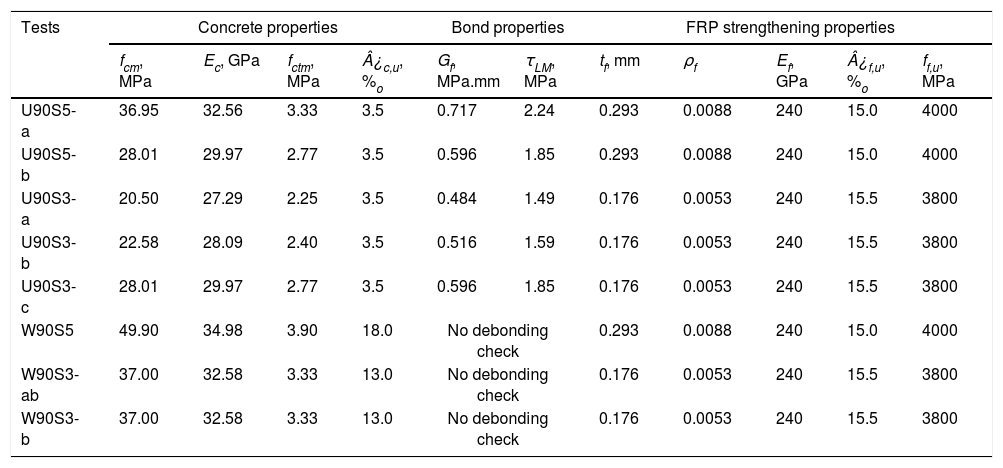
The material properties of concrete and FRP considered in the model are listed in Table 1. For the beam with U-shaped configuration (U90), the parameters related to the debonding failure criteria (τLM, Gf and tf) were determined as function of fcm as shown in Table 1. For steel reinforcement, longitudinal and transversal, the following properties were considered: Es=200GPa, fsy=500MPa, fsu=580MPa, ¿su=0.10. Load was applied incrementally until failure.
Material properties employed in the analysis.
| Tests | Concrete properties | Bond properties | FRP strengthening properties | ||||||||
|---|---|---|---|---|---|---|---|---|---|---|---|
| fcm, MPa | Ec, GPa | fctm, MPa | ¿c,u, %o | Gf, MPa.mm | τLM, MPa | tf, mm | ρf | Ef, GPa | ¿f,u, %o | ff,u, MPa | |
| U90S5-a | 36.95 | 32.56 | 3.33 | 3.5 | 0.717 | 2.24 | 0.293 | 0.0088 | 240 | 15.0 | 4000 |
| U90S5-b | 28.01 | 29.97 | 2.77 | 3.5 | 0.596 | 1.85 | 0.293 | 0.0088 | 240 | 15.0 | 4000 |
| U90S3-a | 20.50 | 27.29 | 2.25 | 3.5 | 0.484 | 1.49 | 0.176 | 0.0053 | 240 | 15.5 | 3800 |
| U90S3-b | 22.58 | 28.09 | 2.40 | 3.5 | 0.516 | 1.59 | 0.176 | 0.0053 | 240 | 15.5 | 3800 |
| U90S3-c | 28.01 | 29.97 | 2.77 | 3.5 | 0.596 | 1.85 | 0.176 | 0.0053 | 240 | 15.5 | 3800 |
| W90S5 | 49.90 | 34.98 | 3.90 | 18.0 | No debonding check | 0.293 | 0.0088 | 240 | 15.0 | 4000 | |
| W90S3-ab | 37.00 | 32.58 | 3.33 | 13.0 | No debonding check | 0.176 | 0.0053 | 240 | 15.5 | 3800 | |
| W90S3-b | 37.00 | 32.58 | 3.33 | 13.0 | No debonding check | 0.176 | 0.0053 | 240 | 15.5 | 3800 | |
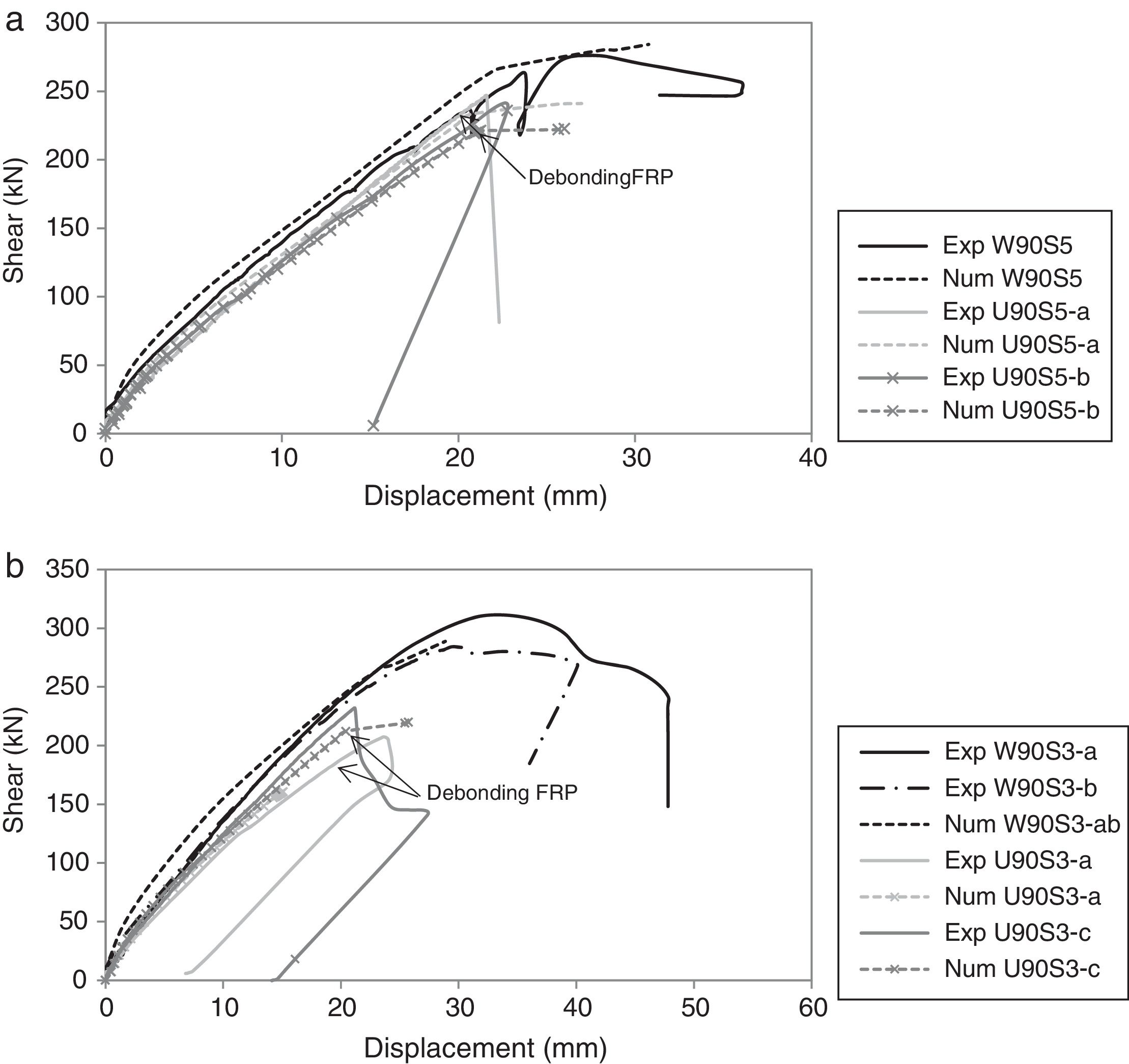
The experimental and numerical shear force vs. deflection at mid span are compared in Fig. 4 for the two beams with different FRP configurations, wrapped (W90) and U-shaped (U90) and for the two series (S5 means series S530 and S3 means series S300). A good agreement was observed between the experimental and numerical results.
 Series S530; (b) Series S300.")
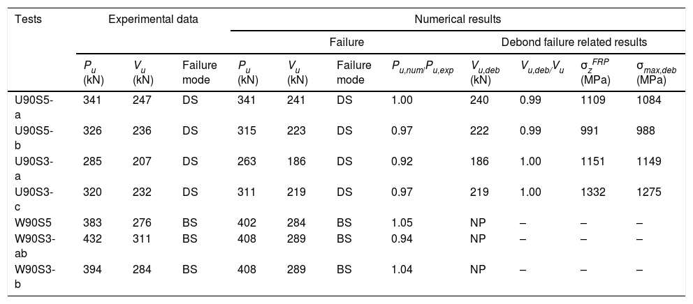
Table 2 gives the numerical results which show a good agreement with the experimental response in terms of ultimate load and along the nonlinear path with increasing load. The model is able to predict a correct failure load of the beams with U-shaped FRP configurations because it accounts for debonding failure. Laminate debonding failure in the U-shaped beam occurs before FRP reaches its maximum strength (3800–4000MPa); as can be seen in the values of σzFRP for the debonding instant in Table 2. When this value exceeds the maximum stress allowed to be transferred, σmax,deb, the debonding mechanism occurs, setting the FRP area of the cross section to zero. From this point forward, this FRP element ceases its contribution to the structural response. For all the U-shaped strengthened beams, the model predicts failure right after debonding occurs, being not able to redistribute the forces; this is consistent with the experimental observations [7]. The beams with the wrapped configurations fail when FRP reaches the ultimate capacity; hence presenting higher ultimate load carrying capacities, which is correctly captured by the model. These results highlight the importance of accounting for the bond failure of FRP in the analysis of shear strengthened elements with U-shaped and side-bonded configurations; disregarding debonding may lead to unsafe predictions of ultimate load capacity as this type of bond is the critical failure mode.
Summary of experimental and numerical results at failure.
| Tests | Experimental data | Numerical results | |||||||||
|---|---|---|---|---|---|---|---|---|---|---|---|
| Failure | Debond failure related results | ||||||||||
| Pu (kN) | Vu (kN) | Failure mode | Pu (kN) | Vu (kN) | Failure mode | Pu,num/Pu,exp | Vu,deb (kN) | Vu,deb/Vu | σzFRP (MPa) | σmax,deb (MPa) | |
| U90S5-a | 341 | 247 | DS | 341 | 241 | DS | 1.00 | 240 | 0.99 | 1109 | 1084 |
| U90S5-b | 326 | 236 | DS | 315 | 223 | DS | 0.97 | 222 | 0.99 | 991 | 988 |
| U90S3-a | 285 | 207 | DS | 263 | 186 | DS | 0.92 | 186 | 1.00 | 1151 | 1149 |
| U90S3-c | 320 | 232 | DS | 311 | 219 | DS | 0.97 | 219 | 1.00 | 1332 | 1275 |
| W90S5 | 383 | 276 | BS | 402 | 284 | BS | 1.05 | NP | – | – | – |
| W90S3-ab | 432 | 311 | BS | 408 | 289 | BS | 0.94 | NP | – | – | – |
| W90S3-b | 394 | 284 | BS | 408 | 289 | BS | 1.04 | NP | – | – | – |
DS, debonding FRP–shear; BS, bending-shear.
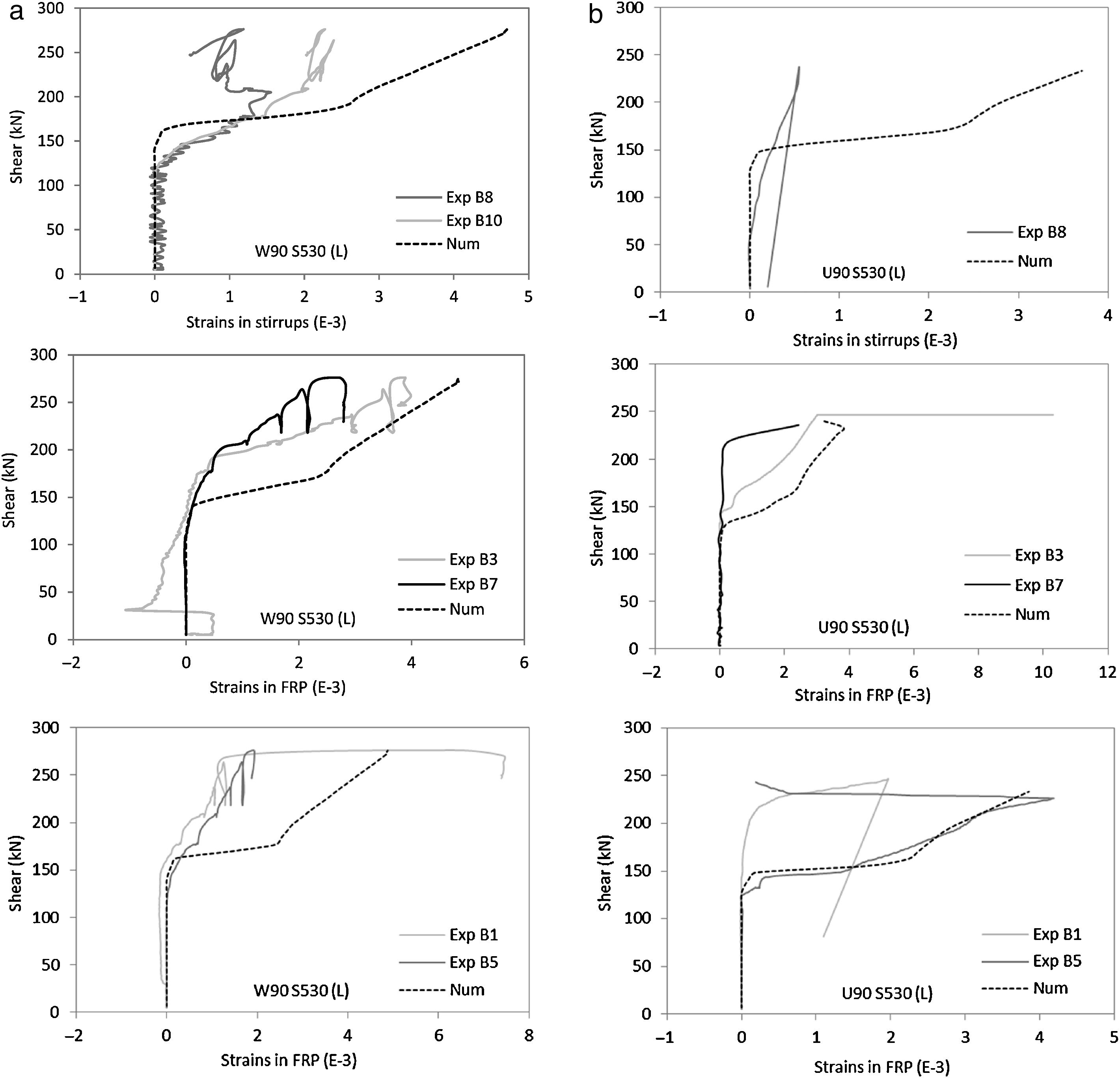
The computed strains in the transversal reinforcement (inner steel stirrups and EB FRP) with increasing shear force are compared with the experimental measurements for the beams with different FRP strengthening configurations (Wrapped and U-shaped). Fig. 5 presents the results of series S530 for location of the sensors see Fig. 3. Only one specimen of each type is represented; the other specimens presented similar fittings.
 wrapped; (b) U-shaped.")
Despite the difficulty of this comparison, due to the discrete form of the real cracks and the assumption of smeared cracking by the model, a good consistency between numerical and experimental results can be observed. The load level for which the stirrups and the FRP reinforcement start to carry load is well captured by the model. This load level corresponds to the outset of diagonal cracking. Sensors 1 and 5 located in the bottom of the beam can be more influenced by bending cracking, and hence, of more difficult comparison. However, in general, it can be observed that the model is able to capture the overall response of the transverse reinforcement.
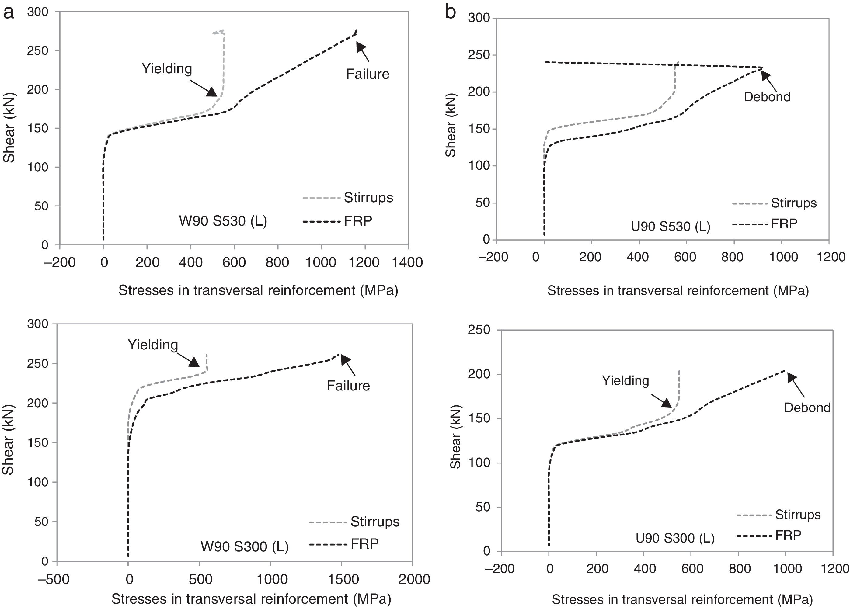
The computed stresses in the transversal reinforcement (stirrups and FRP) are compared in Fig. 6 for the wrapped and U-shaped configurations; these results are related to the mid-height of the cross section at the mid shear span. In Fig. 4b it can be observed the load level for which FRP debonding occurs in the U-shaped beam and the drop of stresses in FRP for onward load levels. After the occurrence of debonding failure, shear stresses are transferred for the steel stirrups that where already yielded at this stage leading to its failure and consequent failure of the beam in shear. For the wrapped configuration (Fig. 4a), the FRP sheets continue to carry load until failure of the FRP; i.e., the load carrying capacity of the FRP is not limited by the loss of bond. In these graphs, the yielding of stirrups instant is also marked; it can be noticed that, before this point, FRP and steel stresses are similar; after yielding, steel cannot increase the load carrying capacity and hence, the FRP increases their stresses significantly. This is observed in both cases, in wrapped and U-shaped configurations.
4Conclusions: (a) wrapped; (b) U-shaped.")
This paper describes the extension of a fibre beam model to simulate EB FRP shear strengthening systems, considering a possible FRP debonding failure in side-bonded and U-shaped configurations. Experimental tests available in literature were numerically simulated. From these analyses the following conclusions are drawn:
- -
The model is able to correctly capture the load-displacement response of the strengthened beams with wrapped and U-shaped configurations;
- -
The model captured the overall response of the transverse reinforcement (inner steel stirrups and EB FRP), capturing the debonding of FRP and subsequent failure of the beams for the U-shaped configurations;
- -
When debonding failure occurs and FRP ceases its contribution to the shear resistance, stirrups were already extensively yielded and were no longer able to absorb the redistribution of forces, and failure occurred right after.
- -
The computational and modelling simplicity makes it suitable to real scale practical applications
The authors want to acknowledge the financial support provided by the Spanish Ministry of Economy and Competitiveness (MINECO) and the European Funds for Regional Development (FEDER), through Research projects: BIA2015-64672-C4-1-R and BIA2015-64672-C4-3-R. The authors acknowledge the support of Albert Alzate, Angel Arteaga, Daniel Cisneros and Ana de Diego from the Instituto de Ciencias de la Construcción Eduardo Torroja of Spain, on the provided data related to their experimental programme.