

Using selective laser melting (SLM) is possible to manufacture molds with cellular internal structures with different porosity degree. Furthermore, internal geometry design can be improved as a function of the desired structural and thermal stress solicitations. In this work two types of cellular internal structures – hexagonal and cub-octahedral – were developed and manufactured using the SLM process. These topologies were generated with the purpose of creating a high degree of internal porosity and getting satisfactory results in terms of thermal and mechanical behavior when compared with similar dimensional bulk structures. The mechanical and thermal behaviors of each cellular topology were evaluated numerically and experimentally through compression and thermal tests. From numeric and experimental results, it can be concluded that hexagonal cellular internal topology provides a higher mechanical strength when compared to the cub-octahedral cellular structure while the thermal analysis shows that cub-octahedral topology is more efficient for heat dissipation. Both cellular topologies have demonstrated, however, to be appropriate for use in injection mold structures. In addition, the use of these cellular topologies provides light weight structuring with an approximate 58% weight reduction, which represents a considerable saving of material total cost to manufacturing of an injection mold.
Consumers are increasingly demanding about the quality of products that they purchase. This reaches a real challenge for the technology of molding by injection of polymeric material. Injection molding has currently a high level of commercial importance as it allows for the acquisition of parts with high dimensional accuracy at high production rates. The need to produce more parts with high quality in a short period of time at a lower cost implies the optimization of injection systems. To ensure dimensional and structural quality of the parts produced, conditions such as the following must be met: (i) the mold must have a sufficiently rigid structure; (ii) the guide that aligns the cavity with the bushing must ensure a perfect alignment; (iii) the power required must be such that the path of the molten material from the nozzle of the injector to the cavity is constant; (iv) the mold temperature should be uniform in part surfaces to ensure that cooling is rapid and efficient; (v) the extraction of the mold parts must be made so that they are not damaged [1,2].
The temperature control of the mold during the injection process is a determining factor for obtaining parts with a good finish and dimensional accuracy. This control is also crucial to reduce part of the cooling time so that it can be removed as soon as possible [2–4]. Optimization of mold cooling processing can undoubtedly lead to a reduction of the effective total time of the injection process, enabling a shorter manufacturing time which leads to a reduction of production costs. Beyond this critical aspect, there is still the issue of the weight of a structure of a mold. This type of structure is until now fabricated by conventional production processes, starting from a steel block and subtracting material to achieve the desired shape. This procedure leads, however, to very high costs of the production tool, to the extent that production becomes a slow process and requires skilled labor at all stages thereof. After finished, the mold is presented with a bulk and heavy structure, difficult to transport and put in injection equipment. The use of cellular internal structures obtained by Additive Manufacturing (AM) processes could optimize the weight of these structures and make a mold into a more sustainable product.
Among AM techniques, selective laser melting (SLM) offers a wide range of advantages, e.g., lower time-to-market, high rate of use of materials, direct production from three-dimensional CAD model, high level of flexibility, i.e. products with different geometries can be produced in the same batch, flexibility of the material being processed, high flexibility in the selection of metallic materials to be used (aluminum, copper, iron, stainless steel, chromium, nickel alloys, titanium and composites of these materials), high production rates, mass customization, versatility, precision, geometric freedom, and the ability to create unique designs with intrinsic characteristics of engineering [5–11]. This explains why, in recent years, the SLM has proven to be among the most efficient additive processes for the production of metal prototypes and parts with complex geometries and has been widely applied in different areas of industry, e.g., automobile, aerospace and aeronautics, construction civil, textile, retail, medicine and, more recently, in the production of scaffolds in engineering of human tissues and teaching [12–21]. In addition, the ability to create functional components with mechanical properties compared to the properties of powder materials that gave rise to these, or even the creation of components with improved surface properties such as hardness, abrasion resistance and corrosion, among others, gives to SLM a prominent place within the range of AM techniques. Allied to these advantages, it is also unquestionable that another great advantage of SLM is associated with the production of components with high mechanical strength through the generation and optimization of internal topologies consisting of thin walls, hidden voids and channels, i.e., with a specific porosity degree, which represent a global reduction weight of components, without loss of stability, reliability and mechanical strength of produced parts [11,13,21–24]. This approach is particularly relevant to the industries related to injection molding and molds production where cellular internal structures can be used instead of bulk parts. Regardless of geometry complexity, the use of SLM in the production of molds allows the optimization of the design of cooling channels, which ensures injection product quality and increasing productivity [25].
The purpose of this work is therefore the study of alternative cellular internal structures of a mold in order to be able to withstand the injection pressures and additionally increases the thermal efficiency thereof without loss finish quality. The cellular internal structures developed are lattice volumes with conformal cooling channels configured according to injection molding procedure. In short, it is intended to choose an internal structure for a mold allowing the reduction of weight and the amount of material in the production of the mold, as well as an improved thermal behavior of the structure so as to lead to the manufacturing of products with better quality and high production rates. To achieve this, two mold inserts with high degree of internal porosity, were developed and produced using the SLM process. The mechanical and thermal behaviors of each one were evaluated numerically and experimentally through compression and thermal tests.
2Design of internal cellular structuresThe possibility of producing prototypes with high porosity, but also resistant, through internal topologies modeled in the design phase, is one of the great advantages inherent in SLM manufacturing processes [11,13,21–24,26–28]. The purpose of this study is to demonstrate that the application of these concepts in the molds industry may eventually allow for the production of significantly lighter and functional molds with an improved thermal performance without production reliability loss.
One way to modeling internal topologies is from Boolean operations, through the union, subtraction or the intersection of two or more entities or objects [26]. However, for this work it was decided specifically to set aside this mathematical tool and opt for the root of the unit cell lattice structures geometry modeling using a 3D Computer Aided Design (CAD) software – SolidWorks®, and amongst these, stochastic porous structures were not considered. In fact, periodic cellular lattice structures are light-weight structures that seem to provide advanced or multifunctional performance for high value engineering products, such as injection molds, rather than those achieved with stochastic porous structures [22,23].
For the development of cellular topologies design – periodic cellular structures, using a 3D CAD tool, the first phase involves the creation of an inner unit cell structure model. This step is proceeded by units aggregation to create a 3D block composed of several structures until the desired dimensions are reached, i.e. specimens are building repeating units in the three different directions originating a cohesive whole in which all units are in contact within each other surrounding units [23,29]. Moreover, it is necessary to ensure connectivity between several unit cellular structures in order to obtain a rigid global structure with stable and homogeneous mechanical properties.
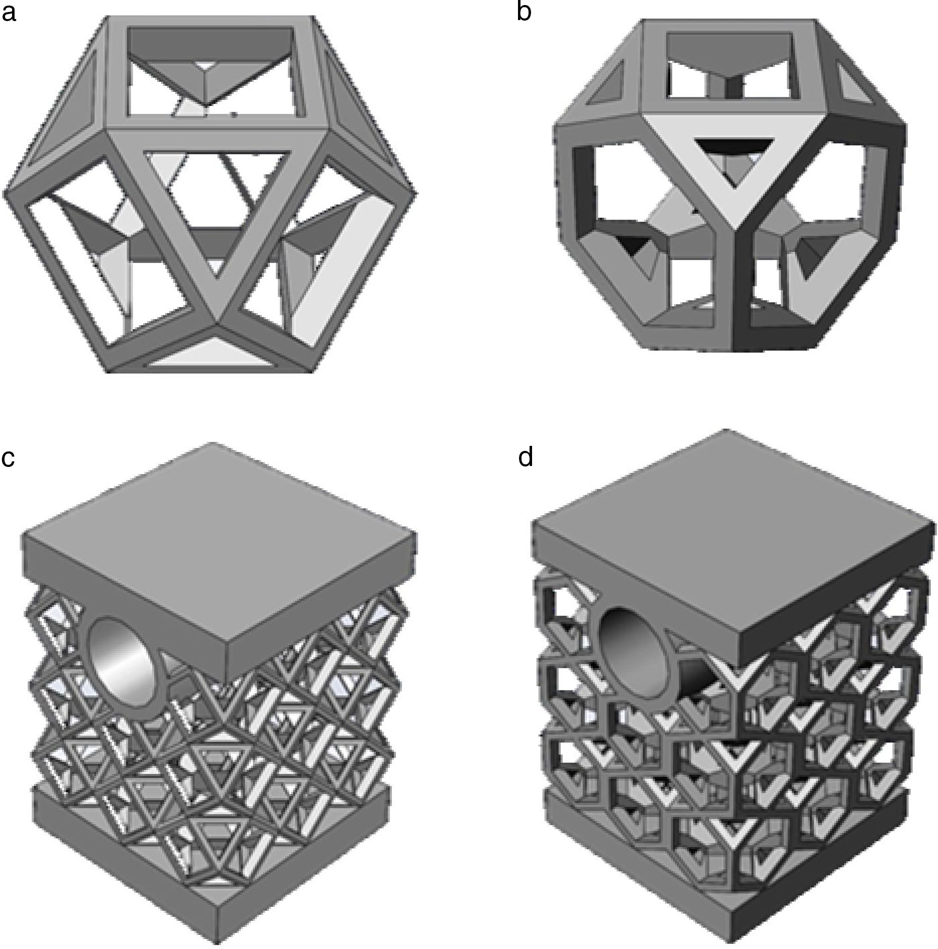
References [28,30,31], for instance, presented a detailed review on cellular internal structure architectures produced by AM technology, e.g. cylindrical, hexahedral, octahedral, dodecahedra, and so on. Based on the research conducted to select proper internal geometries to be used in injection mold fabrication and manufactured by SLM process, two distinct unit cells with different internal topology were designed: (i) a cub-octahedral unit and (ii) a hexagonal unit as shown in Fig. 1a and b, respectively. The cub-octahedral unit selection was based on lattice structures due to its well-known good mechanical behavior [11,22,32]. The second structure – hexagonal cellular unit – gets its inspiration from nature, specifically in honeycombs created by bees.
 cub-octahedral and (b) hexagonal cell structure and 3D CAD model of test body designed with (a): (c) cub-octahedral and (d) hexagonal cellular internal topology.")
Cellular structures have been widely used as energy absorbers to withstand external loads, due to its high energy absorption capacity [11,13,21–24]. The mechanical behavior of this type of structure geometry has also been the target of a strong study over the years [11,23,27,28,31,33–37].
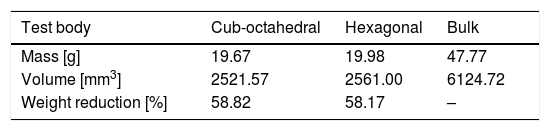
In order to perform the study of mechanical and thermal behavior of parts with internal structures built with unit cellular structures shown in Fig. 1a and b, it was necessary to design test body by repetition of each respective unit. Fig. 1c and d illustrates for cub-octahedral and hexagonal internal geometries the test bodies designed and that will be manufactured by SLM. The final internal architecture of test bodies is the result of a design fit process performed from each unit cell to obtain a global harmony of the set composed of several cellular units. These samples are intended to simulate a portion of the part surfaces of a mold structure. The upper face simulates the cavity surface that would be in contact with the melted material and the circular hole represents the cooling channel near the part surfaces. The samples from part surfaces, for testing, were designed having about 17mm long by 17mm wide and 23mm high. The water channel has 6mm of internal diameter with 3mm thickness walls. Table 1 summarizes the test bodies information concerning to their mass and volume, and the obtained weight reduction when compared with a bulk test body.
3Numerical modeling3.1Finite element modelingThe use of Computer Aided Engineering (CAE) codes in the development of a product becomes an essential tool for the optimization of product characteristics themselves. Additionally, a reduction of products time-to-market and cost production were achieved. Based on Finite Element Method (FEM) the software SolidWorks® integrates a simulation tool capable, among others, to perform static, thermal, dynamic, fatigue and buckling analysis [38]. Finite Element (FE) simulations can provide, in a quickly way, detailed information on stress and deformation distributions when structures are submitted to several loading and boundary conditions. This is not only very useful for the structures optimization process, but it also allows for the characterization and quantification of structure responses, which are difficult to measure experimentally. FE models need, however, to be accurately formulated to produce realistic results [31]. Finite element mesh quality itself depends on finite element types chosen to discretize the geometry and on Aspect Ratio (AR), which is a relatively simple measure that quantifies the shape of each element in the mesh generated.
In order to assess the influence of each one of the internal cellular topologies on the mechanical and heat transfer behaviors of the test bodies developed, a numerical study was conducted. The predictions of the FE numerical results will be compared to experimental compression and temperature tests results in order to validate them. In this work, as a first possible approach, tetrahedral solid elements are selected to numerically model the cellular topology types under analysis [11,31]. For tetrahedral elements, the AR is measured as the ratio of the longest edge length divided by the minimum height of the lower side [39–41]. The most reliable solutions are achieved when the AR is close to the value 1. However, unit values for AR can result in a very heavy mesh, hard to build and with unnecessary elements [42]. For hexahedral elements and acceptable results, AR values are from 1 to 3. In contrast, AR values among 3 and 10 means that the results must be treated gently and for AR greater than 10, must be taken into account with alarm [42,43]. Concerning tetrahedral elements, there is less information, but [41] pointed out that elements with AR between 1 and 4 produce optimal results. Furthermore, it is recommended that the percentage of elements with AR greater or equal than 3 remains below 5% [44].
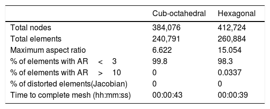
Table 2 summarizes the mesh parameters obtained for both cellular internal topologies. As shown in Table 2 high quality meshes were obtained. For cub-octahedral geometry notwithstanding, an AR maximum 6.62 is verified, 99.8% of elements have an AR lower than 3. The elapsed time for building mesh was only of 43s. It is obviously expected that the specimen dimensions as well as its porosity degree have a great influence on elapsed time. For hexagonal topology a maximum of 15.054 is reached for the AR value. Taking into account the already explained, this value can be considered as alarming. But if the parameter percentage of elements with an AR greater than 10 is considered, a value much less than 1% (0.0337) of the total elements has an AR greater than 10. In addition, it is found that 98.3% of the total number of elements have an AR smaller than 3. Nevertheless, this shortcoming has been the target of correction. The elapsed time for building mesh was, however, much higher. Therefore, it was decided to proceed with this study with the mesh corresponding to a mesh generation time of 39s.
Detailed information mesh.
| Cub-octahedral | Hexagonal | |
|---|---|---|
| Total nodes | 384,076 | 412,724 |
| Total elements | 240,791 | 260,884 |
| Maximum aspect ratio | 6.622 | 15.054 |
| % of elements with AR<3 | 99.8 | 98.3 |
| % of elements with AR>10 | 0 | 0.0337 |
| % of distorted elements(Jacobian) | 0 | 0 |
| Time to complete mesh (hh:mm:ss) | 00:00:43 | 00:00:39 |
Since one of the purposes of this work is to compare numerical results with experimental results in what concerns compression mechanical tests and heat transfer performance, the full details of the experimental tests were recreated accurately in mechanical and thermal numerical studies. Concerning load and boundary conditions, numerical study was conducted by applying a static load of 10kN, corresponding to a compression stress value of 34.6MPa, distributed on the upper area of the test body. This load value corresponds to a pressure of 340bar, which is fairly common value in injection molding applications. Constraints of no displacements and no rotations were applied to the specimen base, which means that it was rigidly fixed. Both trials of each of the different cellular topologies meet these conditions.
The tool steel AISI H13 (DIN X40CrMoV5-1, UNS T20813, ASTM A681) was chosen due to its wide use in injection molding industry. This steel tool is ideal for working hot such as casting molds, extrusion tools, forging dies, hot stamping dies and plastic molds [43,44]. Properties such as high hardness, excellent wear and temperature resistance combined with good polishing ability, high toughness to hot, excellent tensile properties of hot and a good thermal shock resistance justify that AISI H13 is the most commonly used steel in applications that require cooling such as injection molding industry. It should be noted that the literature available so far works on various metal powders e.g. stainless steel, titanium and titanium alloys, nickel base super-alloy, cobalt-chromium alloy, and so on, which can be processed by SLM process [24], papers focused in AISI H13 powders processed are sparse, reason why the comparison of the results achieved in this work was a hard task.
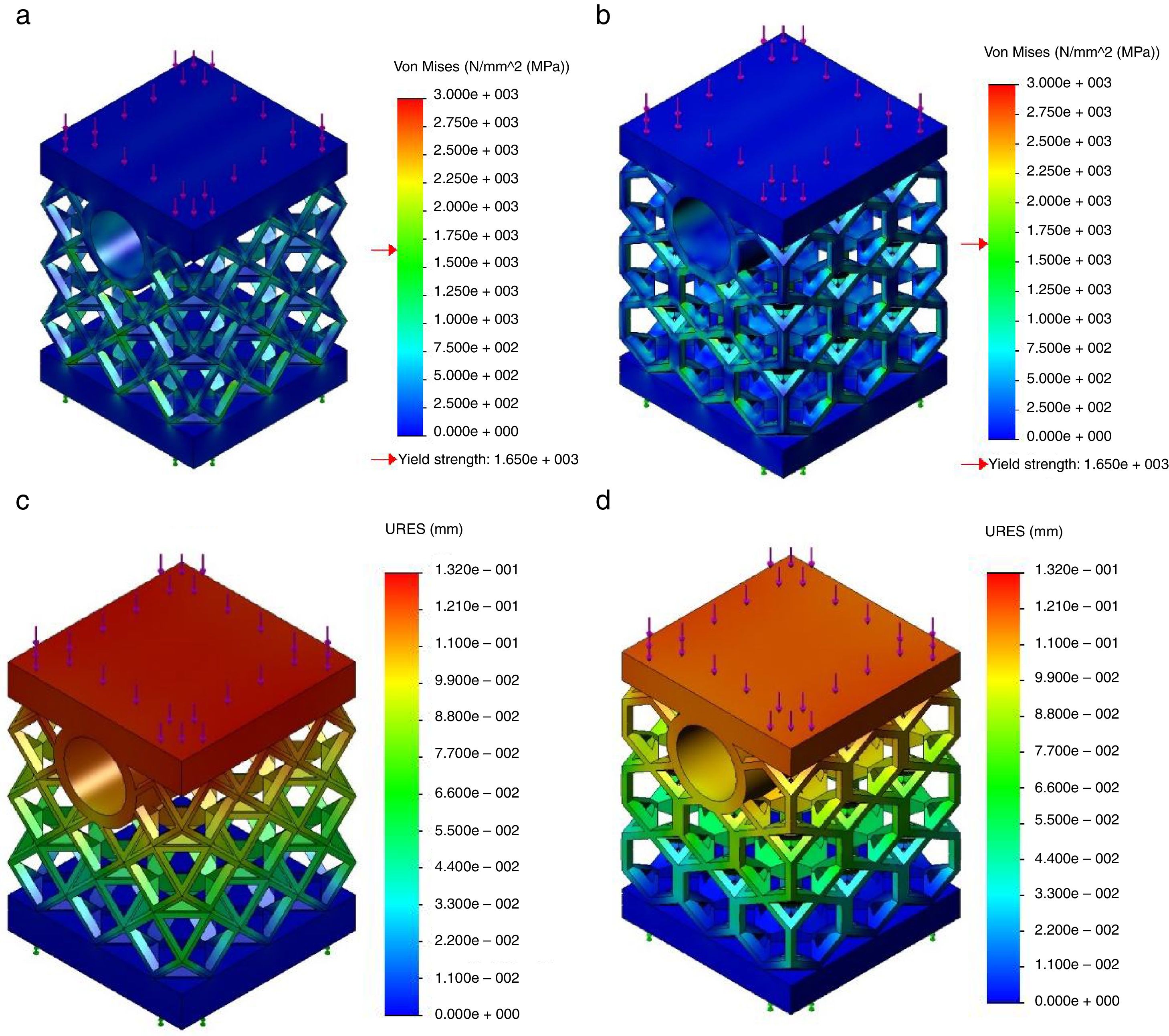
3.2Mechanical compression testsAs already referred the mechanical strength of the two cellular internal geometries was evaluated performing compression tests under the conditions described above. Fig. 2a and c illustrates the Von Mises stress and displacement fields obtained, respectively, for cub-octahedral internal topology while hexagonal topology stress and displacement distributions are shown in Fig. 2b and d, respectively.
 cub-octahedral and (b) hexagonal cellular internal topology; displacement field for (c) cub-octahedral and (d) hexagonal cellular internal topology.")
From these results and as it is expected due to their similar density degree no significant differences are observed between the cub-octahedral and the hexagonal topology in stress field terms. For the level of load applied, 10kN, and for both topologies – notwithstanding that a large part of the body test is subject to a tension well below to the yield material strength – in some locations of the specimen plastic deformation occurs, i.e. the yield material strength is exceeded. This means that an optimization design procedure is required and should be performed to avoid this phenomenon. Such optimization procedure can include geometric changes, dimensional changes or both. Concerning deformations occurrences, a clear decrease in the global displacement values is observed for the hexagonal topology, which demonstrates its superior behavior when submitted to compression loads. Perhaps the increase, although small, of the mass of the hexagonal topology relatively to the one that characterizes the cub-octahedral topology may justify the performance observed.
3.3Thermal testsThe numerical study of thermal behavior of both cellular internal structures developed was also performed to provide a set of results to be compared with experimental heat transfer tests. The comparison of results provides the accuracy evaluation of FE models developed, as well as numerical results validation. In order to replicate what happens in the refrigeration process of a mold, a temperature evenly distributed is applied in the circular hole that represents the cooling channel at molding area. This procedure is experimentally simulated by use of an electric heater that is placed within the cooling channel and the heat transfer process – range of temperatures – evaluated through a thermal image equipment. This issue will be presented in detail at the next section.
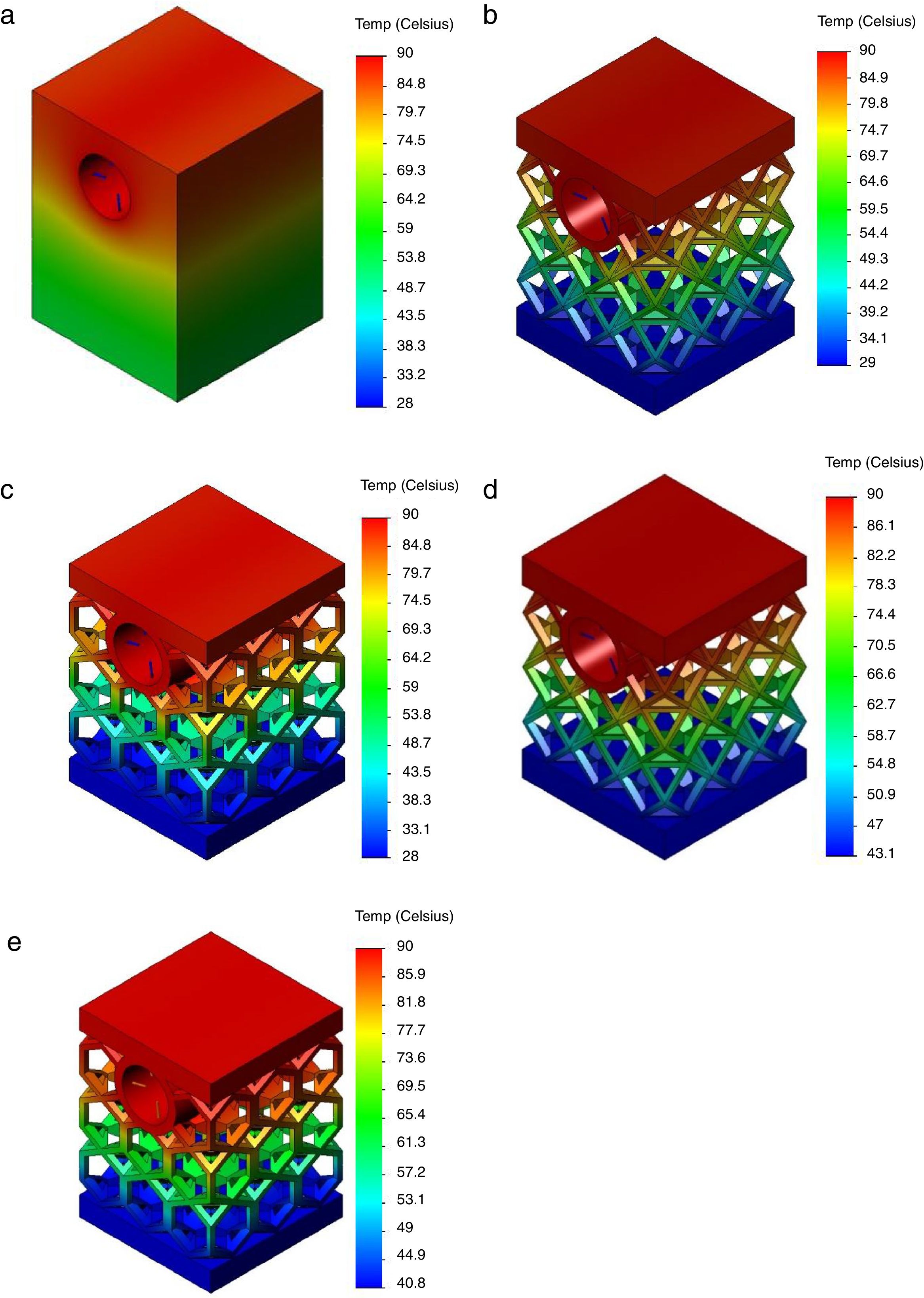
The thermal numerical study was conducted considering an average value of 25°C for the environment temperature and by applying a temperature of 90°C in the cooling channel. The convection phenomena between the test body and the environment were neglected, only the conduction over the solid was considered. This last temperature value was chosen taking in account the specimen dimensions. Additionally, the introduction of a very high starting temperature would lead to a rapid conduction of heat, which would hinder the procedure of analysis results. The results of thermal tests were first analyzed at the end of 15s after the temperature application and the second analysis happened after the elapse 45s of test. Fig. 3a shows for the bulk structure the temperature distribution elapsed 15s after applying the temperature of 90°C in the cooling channel. As can be observed the temperature of almost upper half of the specimen reaches the 90°C while to the bottom half a temperature of around 60°C is verified. Between these two temperature values a slight gradient of temperature occurs. Fig. 3b and d shows, for the cub-octahedral specimen, the temperature distribution elapsed 15 and 45s after applying the temperature of 90°C, respectively. From Fig. 3b it can be concluded that at the end of 15s the temperature of the top of the specimen, which corresponds to the molding zone, reaches the temperature value induced in the cooling channel, i.e. 90°C. In addition, a slightly increase of temperature value, of approximately 29°C, is verified at the specimen base. For the elapsed time of 45s, the specimen base temperature increases to 43°C maintaining the specimen top temperature of 90°C since there is no further flow of heat input greater than this temperature.
 on the bulk test body; (b) and (d) on the cub-octahedral topology elapsed 15 and 45s after applying temperature; and (c) and (e) on the hexagonal topology elapsed 15 and 45s after applying temperature.")
Concerning hexagonal type of cellular internal geometry, Fig. 3c and e displays the temperature distribution elapsed 15 and 45s after temperature of 90°C application, respectively. No significant differences are verified relatively to the observed for cub-octahedral geometry. At the end of 15s the temperature of base specimen was of approximately 28°C, while after 45s this temperature reached the value of 40°C. The cub-octahedral geometry is characterized by a high mass value when compared with those of hexagonal geometry which could justify the small amount of energy dissipation efficiency. This behavior is enlarged when the bulk structure is compared with both cellular topologies.
It was nonetheless analyzed how long it would take the induced temperature of 90°C to reach the top of specimens with different cellular topologies. For cub-octahedral topology, this action takes place in 10.2s to time. The temperature of the base takes the value of 26°C. For the hexagonal topology a time of 10.4s is elapsed until the temperature of 90°C is reached at the specimen top face. The same temperature of 26°C is verified at the base. Thus, it can be concluded that, although a meaningful difference is not observed, the cub-octahedral presents a behavior that could be more appropriate for the intended application since it can transfer the heat to the molding zone more quickly for the same base temperature.
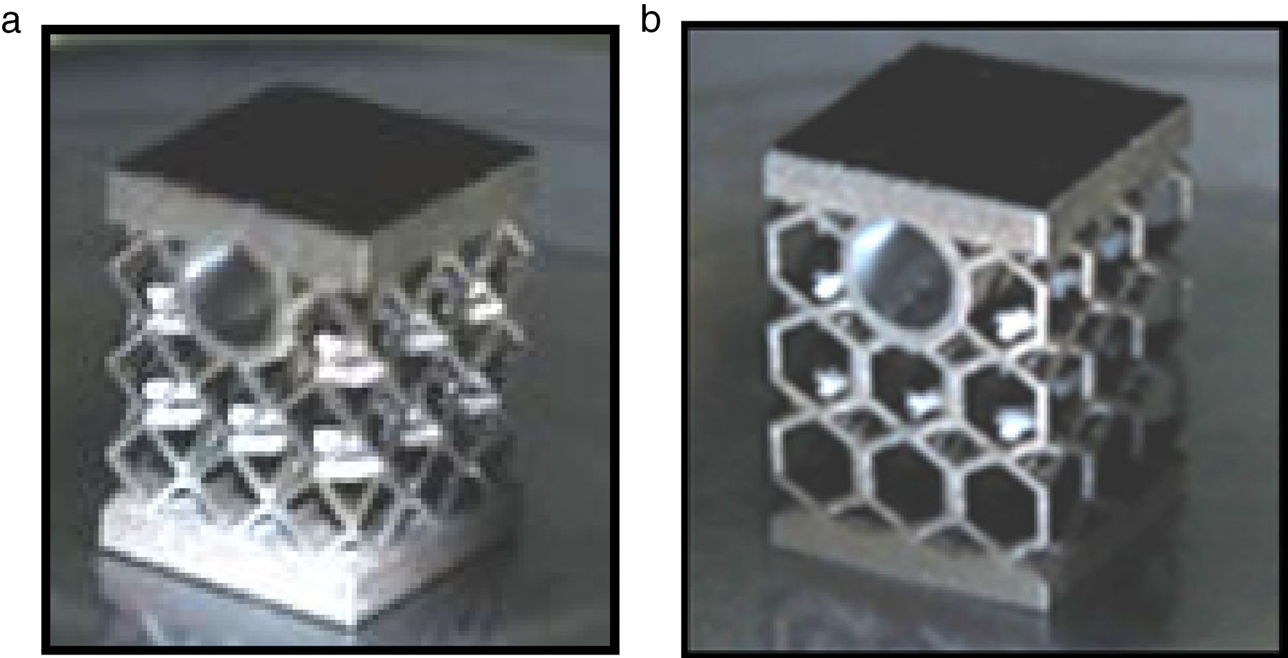
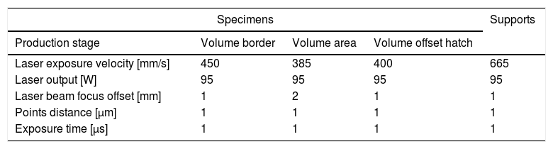
4Experimental testsAs the purpose of this work is the analysis of cellular internal topology influence on the mechanical and thermal behavior of injection molds, the SLM additive manufacturing technology was selected since it provides the construction of metal parts with complex cellular topologies. A set of test specimens of both cellular internal structures modeled in Section 3 were produced from AISI H13 powders and submitted to compression and thermal tests to validate numerical results. For the production of test specimens, a SLM 125HL equipment of SLM Solutions GmbH was used. The processing parameters selected are described in Table 3. Fig. 4 shows both cub-octahedral and hexagonal cellular topologies specimens produced by SLM.
Construction parameters of test specimens.
| Specimens | Supports | |||
|---|---|---|---|---|
| Production stage | Volume border | Volume area | Volume offset hatch | |
| Laser exposure velocity [mm/s] | 450 | 385 | 400 | 665 |
| Laser output [W] | 95 | 95 | 95 | 95 |
| Laser beam focus offset [mm] | 1 | 2 | 1 | 1 |
| Points distance [μm] | 1 | 1 | 1 | 1 |
| Exposure time [μs] | 1 | 1 | 1 | 1 |
 cub-octahedral and (b) hexagonal cellular internal topologies.")
Since one of the purposes of this work has been the study on the applicability and suitability of internal cellular structures with different topologies to metal pieces of injection molds, typical loads of injection process are applied to the specimens produced as described before. It must be highlighted that in the absence of a specific standard for this type of application and dimension built structures, the ISO 13314 – “Mechanical testing of metals ductility testing – Compression test for porous and cellular metals” was applied to perform compression test since it is the standard most closely to the kind of structures produced. In fact, the test specimen dimensions required for ISO 13314, width and height, should be at least ten times the diameter of a pore. Nevertheless, the compliance of this condition would lead to a specimen of considerable dimensions, which would result in high cost and a much higher construction time, making it economically impossible to build a specimen in numbers enough to perform experimental tests.
Compression tests were performed using an INSTRON 4505 equipment with a load cell of 100kN. The specimens were placed on the center of the bottom plate of INSTRON machine and the load gradually increased with a velocity of 2mm/min. After specimen's breakage occurrence the test was stopped. The maximum values of stresses were obtained analytically by σ=F/A, where F is the applied compressive load and A the area of the specimen cross section with a value of 289mm2.
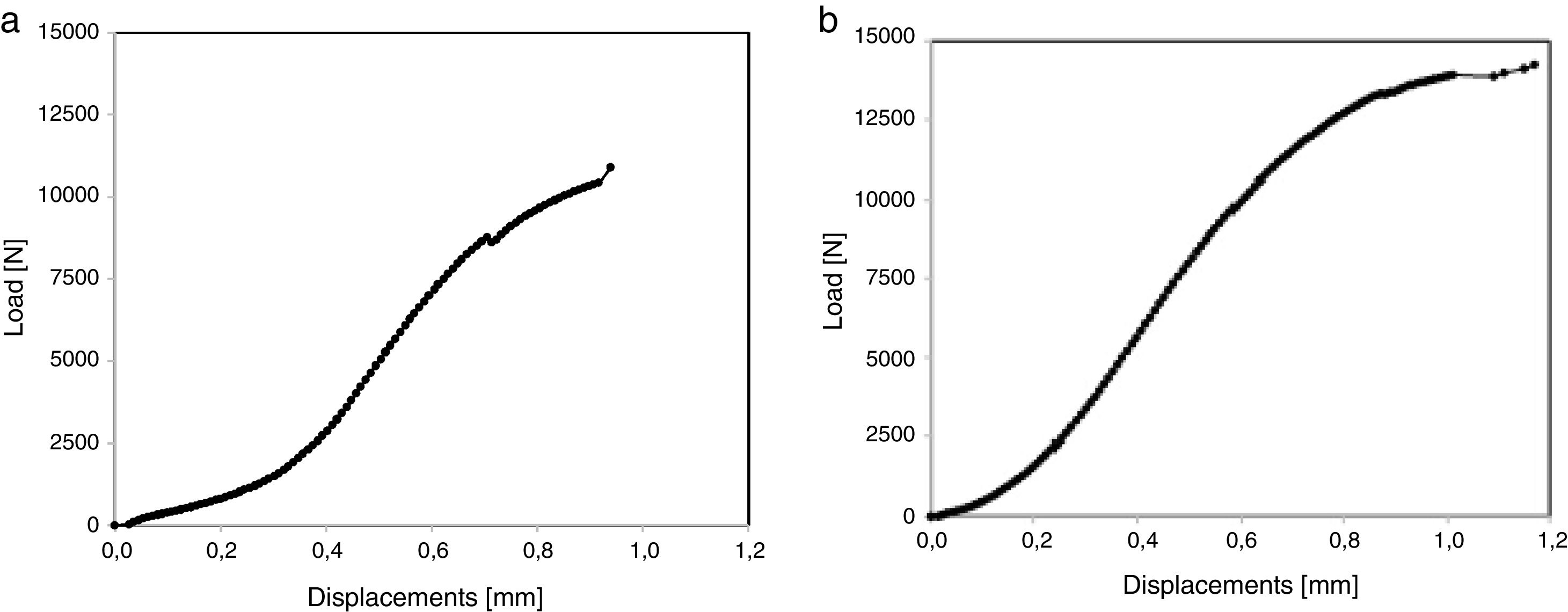
For each trial, the load values applied and the resulting deformations were recorded using the data acquisition software of INSTRON. The data acquired, in the form of text file, were further analyzed and from them the Load vs. Displacement curves for each cellular internal topology manufacture. Fig. 5a and b illustrates the load vs. displacement curves for the cub-octahedral and hexagonal internal topologies, respectively. Each curve was calculated as an average from the data acquired for the maximum load and the corresponding displacements on the specimens tested.
 cub-octahedral and (b) hexagonal cellular topology.")
For the cub-octahedral internal geometry, as shown in Fig. 5a, specimen's breakage occurs for a maximum compression load of 10.9kN, corresponding to a stress value of 37.7MPa. The maximum displacement average obtained was 0.94mm. Regards to hexagonal topology rupture happened for a maximum load value of 14.25kN, equivalent to 49.31MPa, and a maximum displacement of 1.17mm as displayed in Fig. 5b.
From these results it can be concluded that cellular hexagonal topology presents a higher mechanical strength, than those observed for cub-octahedral internal topology, thereby making its application possible for an internal structure of injection molds for varied applications. For both cellular topologies the results experimentally obtained, stresses and displacements, were superior to those computationally achieved by numerical analysis.
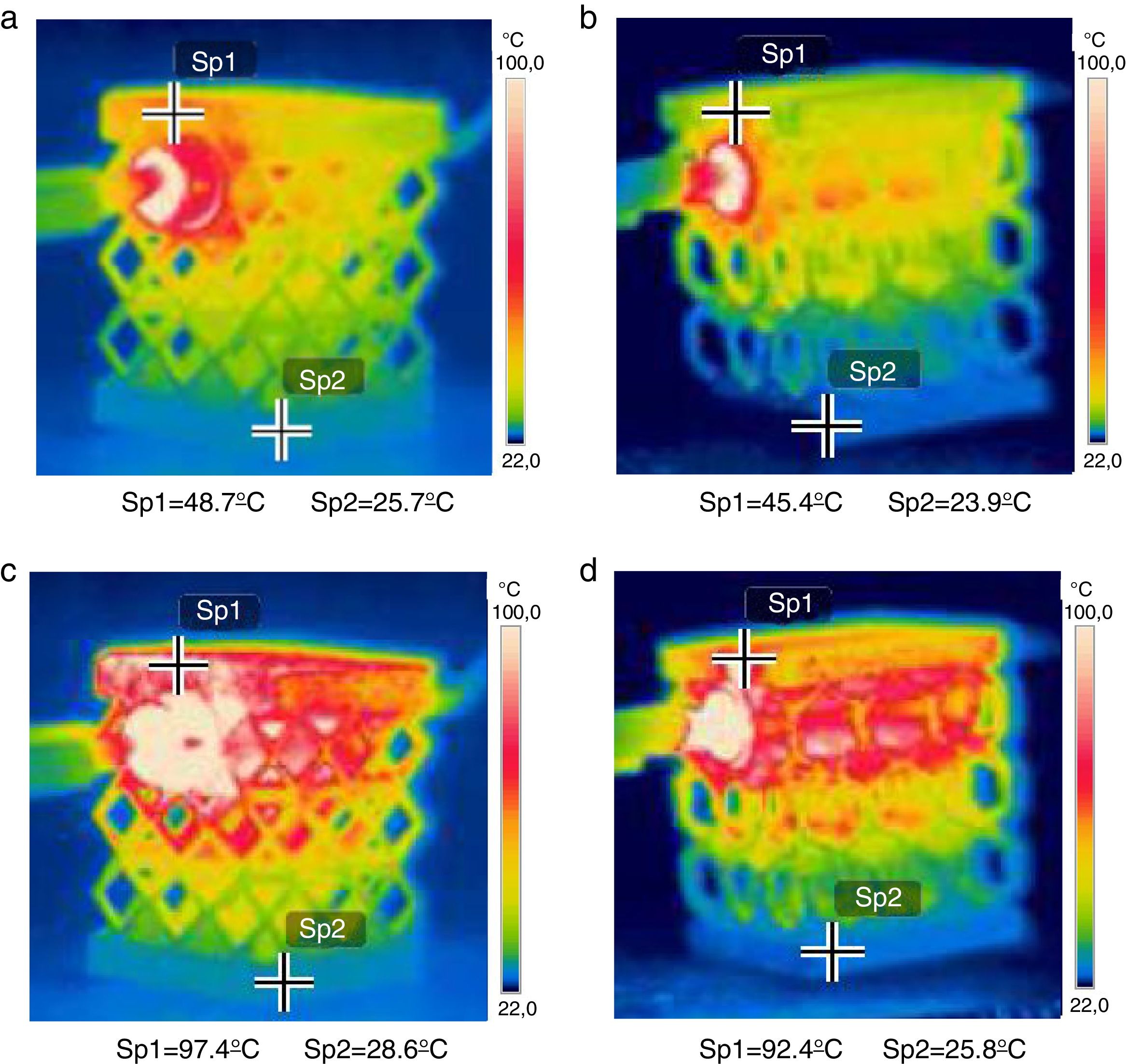
4.2Experimental thermal testsSince it was not possible to perform thermal tests in an adiabatic room it was difficult to replicate with enough accuracy the conditions applied in the computational simulation. Experimental measures of heat transfer therefore suffered the influence of certain parameters difficult to be controlled by the user. Some of these parameters are the room air temperature, where experimental tests were done varying between 23°C and 25°C, and the heating resistance began at a temperature room and took a few seconds to reach 90°C, while in numerical study the temperature starts at 90°C keeping this setting value. Nonetheless the thermal tests were conducted using a heating resistance, accompanied by a thermocouple connected to a control board on which one could set its temperature, and subsequently temperature values over time recorded by using a thermal imager FLIR T650SC. Another thermocouple was used to verify temperature values. A set of three images were taken in each test, one in the initial state, another 15s after application of the heat source and the last elapsed 45s of test as was done in the numerical study. The images were subsequently processed and analyzed using the FLIR tools software so that they can be compared with thermal computational results. For all the tests performed an emissivity of 0.62 was taken for AISI H13 according to that reported by [45]. Fig. 6a–d shows the images supplied by the thermography machine for the cub-octahedral and hexagonal specimens, respectively, after 15 and 45s after the test has started.
 15 and (c) 45s after heat source application and on the hexagonal topology elapsed: (b) 15 and (d) 45s after heat source application.")
For the cub-octahedral topology and after 15s from the start of the test, the top of the test specimen reached the 48.7°C of temperature, whereas at the bottom the temperature was maintained near ambient temperature with the value of 25.7°C as shown in Fig. 6a. After elapsing 45s of test, the temperature at the specimen top increases to 97.4°C and the base temperature suffers a slightly increase with a value of 28.6°C, as can be seen in Fig. 6c. Regarding hexagonal topology, as demonstrated in Fig. 6b and d, the specimen top reached the temperature of 45.4°C and 92.4°C, respectively, for 15 and 45s after heat source application. The bottom temperature increased from 23.9°C to 25.8°C with the increase of elapsed test time from 15 to 45s.
From the set of thermal results experimentally obtained it can be concluded that regardless of the elapsed time value, 15 or 45s, specimens with a cub-octahedral internal topology have a better heat conduction behavior than the hexagonal subject topology since higher temperatures were verified. Both specimens are presented as good heat conductors, better to the specimen top than to the bottom, which is not surprising due to the proximity of the location of heat source application. Nonetheless the cub-octahedral topology has presented a superior thermal behavior because both temperatures, at the top and at the bottom, were greater than those verified for the hexagonal specimens. In addition, the time required to reach maximum temperature was greater for the hexagonal topology. These results are according to those obtained computationally.
5ConclusionsThe combination of the injection molds production with the advances of AM technologies emerged as a quicker and more sustainable alternative to the construction of these structures. Taking full advantage of SLM additive manufacturing technology, it is possible to improve the internal topologies of these bulk structures, turning them into more appropriate cellular structures for the desired structural and thermal load solicitations. Applying this methodology, a dramatically reduction of the structure overall weight and the decrease of the amount of material required for molds pieces production can be reached. With these purposes, test bodies representing parts of mold structure with two different types of internal topology were built by SLM technology. The development and generation of both internal topologies had the main objective to obtain a high degree of internal porosity while still get satisfactory performances in terms of thermal and mechanical behavior when compared with the corresponding bulk structures.
The mechanical and thermal behaviors of each developed internal topology were evaluated numerically and, subsequently, evaluated experimentally through mechanical compression and heat transfer tests. Both results, numeric and experimental, showed that both cellular topologies were good conductors of heat. The heat is, however, conducted more quickly to the top, which corresponds to molding area, than for to the bottom of the structure. This is the ideal condition for molds structures, since it is imperative that the applied heat should be rapidly conducted to the top while the opposite phenomenon should happen at the base in order to improve cooling and heating cycles of the molding zone. In addition, it was found that the hexagonal internal topology provides a higher mechanical strength when compared to the cub-octahedral structure, while concerning heat conduction behavior the cub-octahedral topology is more efficient. Both topologies have demonstrated to be appropriate for use in mold structures. The internal design must be, however, an optimized function of a specific application, i.e. for the purpose intended. Regarding the amount of material needed to build specimens with the same dimensions as bulk pieces, it should be highlighted that a saving of about 58% on the material to be processed is reached with the cellular internal topologies developed.
As future work it is imperative to produce molds with the improved internal topologies here presented and test them in real operating conditions. Furthermore issues such as: (i) cellular internal density variation adjusted to different applications; (ii) internal architecture variation in an attempt to find the best possible performance for a given mechanical and/or thermal stress; (iii) numerical and experimental performance, e.g. bending, tensile and fatigue testing of structures in order to thoroughly evaluate the mechanical characteristics of cellular SLM manufactured structures and to compare results with the obtained using the conventionally bulk structures. These matters are currently in development and soon upcoming publications will be dedicated to them.
Research funded by the Project Reference (UID/Multi/04044/2013) from the Portuguese Foundation for Science and Technology.
