


The keel design of the tibial tray is essential for the transmission of the majority of the forces to the peripheral bone structures, which have better mechanical proprieties, thus reducing the risk of loosening. The aim of the present study was to compare the behaviour of different tibial tray designs submitted to torsional forces. Four different tibial components were modelled. The 3-D reconstruction was made using the Mimics software. The solid elements were generated by SolidWorks. The finite elements study was done by Unigraphics.
A torsional force of 6Nm. applied to the lateral aspects of each tibial tray was simulated.
The GENUTECH tibial tray, with peripheral trabecular bone support, showed a lower displacement and less transmitted tensions under torsional forces. The results suggest that a tibial tray with more peripheral support behaves mechanically better than the other studied designs.
El diseño de la quilla de una bandeja tibial es fundamental para la transmisión de la mayor parte de las cargas a las estructuras óseas periféricas, las cuales tienen mejores propiedades mecánicas reduciendo, de este modo, el riesgo de aflojamiento. El objetivo de este estudio es comparar el comportamiento de diferentes diseños de bandeja tibial ante cargas de torsión. Se modelizaron 4 componentes tibiales diferentes. La reconstrucción 3D se llevó a cabo con el programa MIMICS. Los sólidos se generaron en SolidWorks. Se realizó el estudio por elementos finitos mediante Unigraphics.
Se simuló una torsión de 6 Nm aplicada sobre los laterales de cada bandeja tibial.
La bandeja tibial GENUTECH® con apoyo en el hueso trabecular periférico mostró un menor desplazamiento y menores tensiones transmitidos bajo fuerzas de torsión. Los resultados indican que la bandeja tibial con apoyo más periférico tienen un mejor comportamiento mecánico mejor frente a los otros diseños estudiados.
Aseptic loosening is one of the main causes of mobilization of tibial components. The type and quality of fixation, as well as the quality of the adjacent bone, have an influence on the rates of loosening of the prosthesis.1–6 Postoperative bone quality can be measured using bone density indicators. Various monitoring techniques have been developed to determine this index through images taken in vivo during regular patient monitoring. Several authors have related these indicators in order to predict the mechanical behaviour of bone structures.1–7 However, there is currently no consensus on the characterization of the mechanical behaviour of bone, both in trabecular and in cortical areas.1–3
Some studies argue that trabecular bone, peripheral and close to the cortical, has a higher density and, therefore, greater resistance and elastic module than that in the central part.1,2
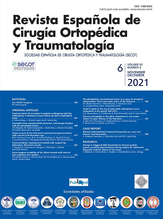
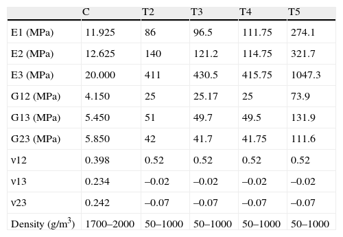
In several studies, Rho (1996)8 and Au et al. (2005),9 proved that the proximal tibial bone has greater resistance in the axial direction than in the radial. This is supported by the characteristics shown in Table 1, which presents the elastic modules of cortical and trabecular bone in the different axes (x, y, z). Z is direction 3 (vertical direction or compression) and, as can be seen, the values of E3 (Z axis or vertical) are notably higher than the values in E1 and E2 (X and Y axes) related to tangential or radial forces. The conclusion is that bone has a better performance under compression loads than under radial loads.
Mechanical properties.
| C | T2 | T3 | T4 | T5 | |
| E1 (MPa) | 11.925 | 86 | 96.5 | 111.75 | 274.1 |
| E2 (MPa) | 12.625 | 140 | 121.2 | 114.75 | 321.7 |
| E3 (MPa) | 20.000 | 411 | 430.5 | 415.75 | 1047.3 |
| G12 (MPa) | 4.150 | 25 | 25.17 | 25 | 73.9 |
| G13 (MPa) | 5.450 | 51 | 49.7 | 49.5 | 131.9 |
| G23 (MPa) | 5.850 | 42 | 41.7 | 41.75 | 111.6 |
| ν12 | 0.398 | 0.52 | 0.52 | 0.52 | 0.52 |
| ν13 | 0.234 | –0.02 | –0.02 | –0.02 | –0.02 |
| ν23 | 0.242 | –0.07 | –0.07 | –0.07 | –0.07 |
| Density (g/m3) | 1700–2000 | 50–1000 | 50–1000 | 50–1000 | 50–1000 |
ν12, ν13, ν23: Poisson coefficient (dimensionless) and density (g/m3) of the proximal tibia according to Au et al.9
E1, E2, E3: elastic modules (MPa); G12, G13, G23: transversal elastic modules (MPa).
The objective of the present study is to assess the influence of the design of the tibial keel on the behaviour of torsion forces through a finite element model. The working hypothesis assumes that different keel designs in relation to the length and the section exposed in the most external tibial area will transmit loads in a different manner to the peripheral bone structures, which have better mechanical properties.
Those keels with a greater length and a greater section in contact with the bone are expected to dissipate tensions better and cause smaller deformations, thus offering a better mechanical behaviour against torsion forces.
Materials and methodsIn this study we conducted a simulation of the mechanical behaviour against torsion forces of the 4 different models of keel existing in the market. In addition, we assessed how tensions derived from torsion were transmitted to the bone. We were able to analyze how implant design affects the reduction of the tension level and its distribution towards the area with a better mechanical behaviour in the proximal tibia.
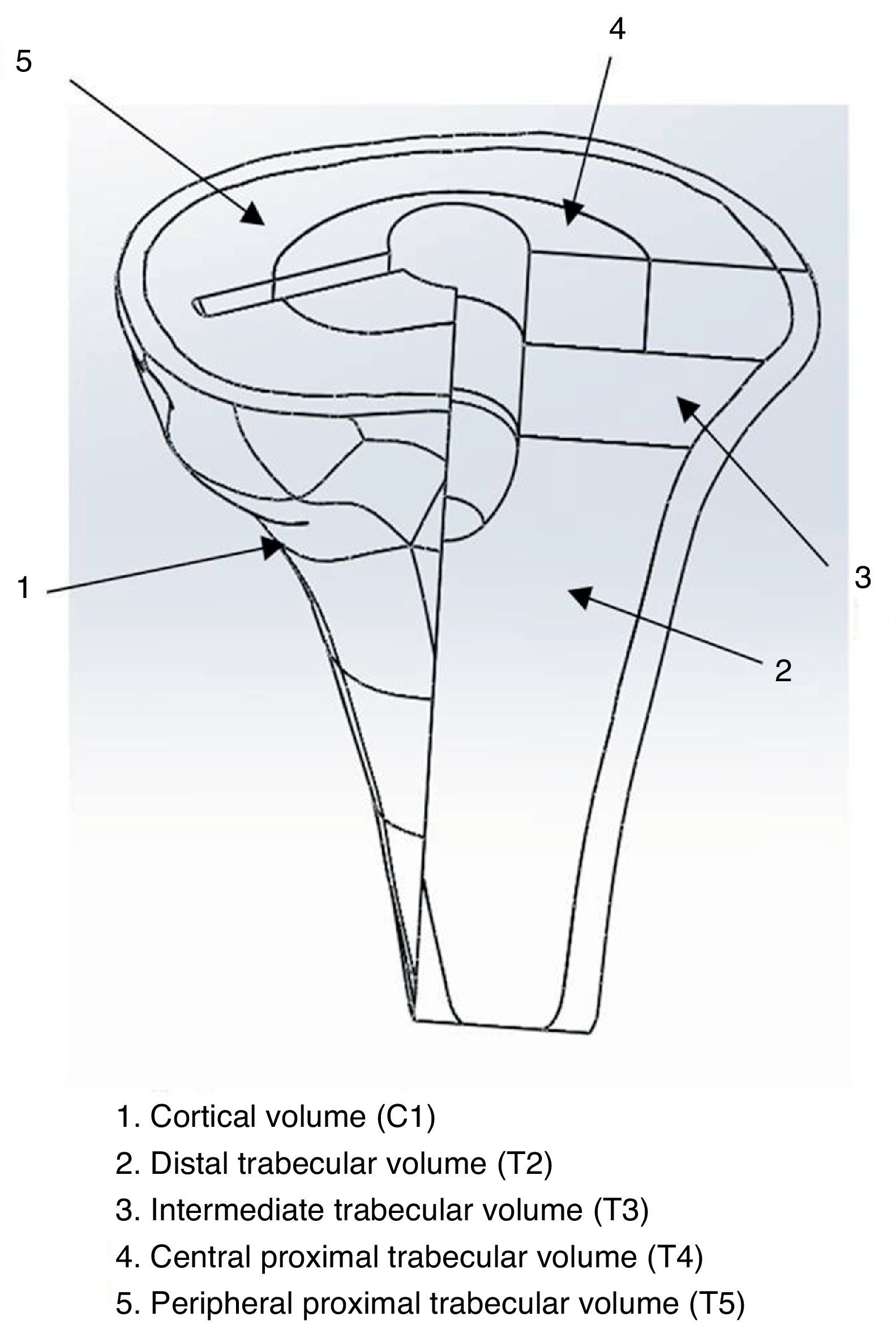
Tibial modelling processAt a specialized Radiology Unit (Hospital Clínic, Barcelona), we conducted a reconstruction of the proximal third of the tibia, into a 3D model, based on computed tomography (CT) data. The solid part was produced using the design software package CAD SolidWorks (Dassaults Systemes SolidWorks Corp., Concord, US) based on the STL file generated by the Biomechanics Institute of Valencia, with the MIMICS reconstruction programme (Materialize HQ Technologielaan 15, Leuven, Belgium). In order to simplify the model, we only used the proximal 100mm of the tibia. We applied a transversal section at 10mm from the superior part of the tibia to establish the support area of the tibial tray to be placed (Fig. 1). The mechanical characterization of the bone regions was carried out based on the properties used in the study by Au et al., 2005.9 The model proposed in the present study was a simplification of the model by Au, grouping areas with similar properties (Fig. 2). The properties by volume can be seen in Table 1.
Preparation of the implant models

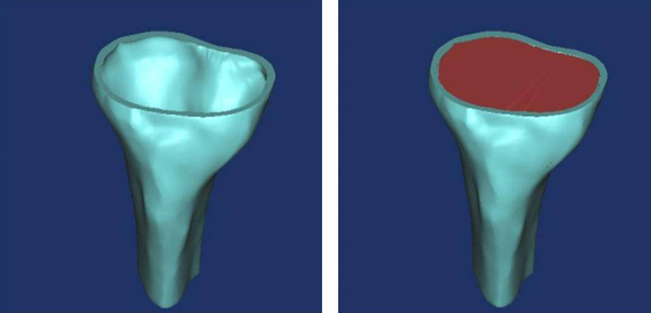
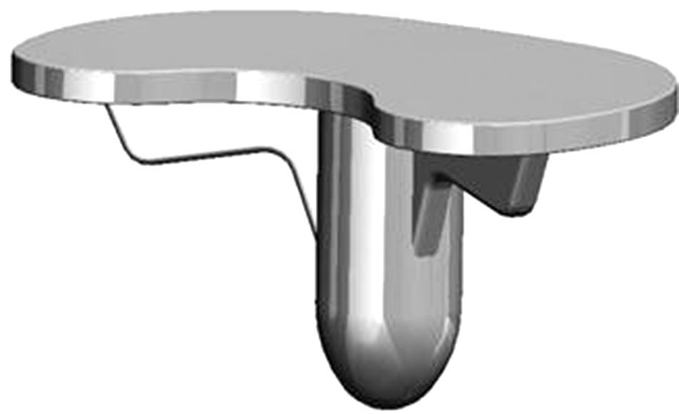
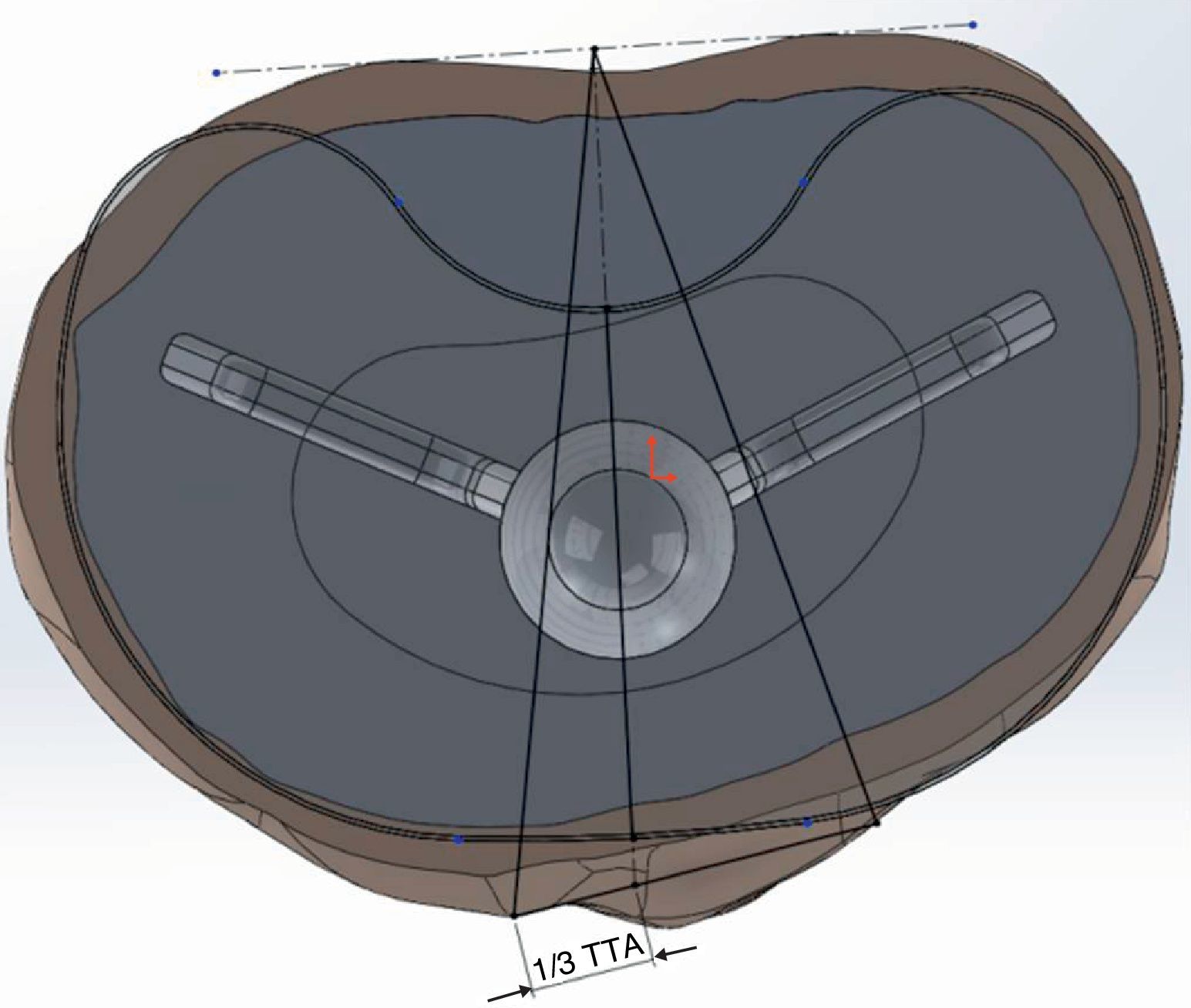
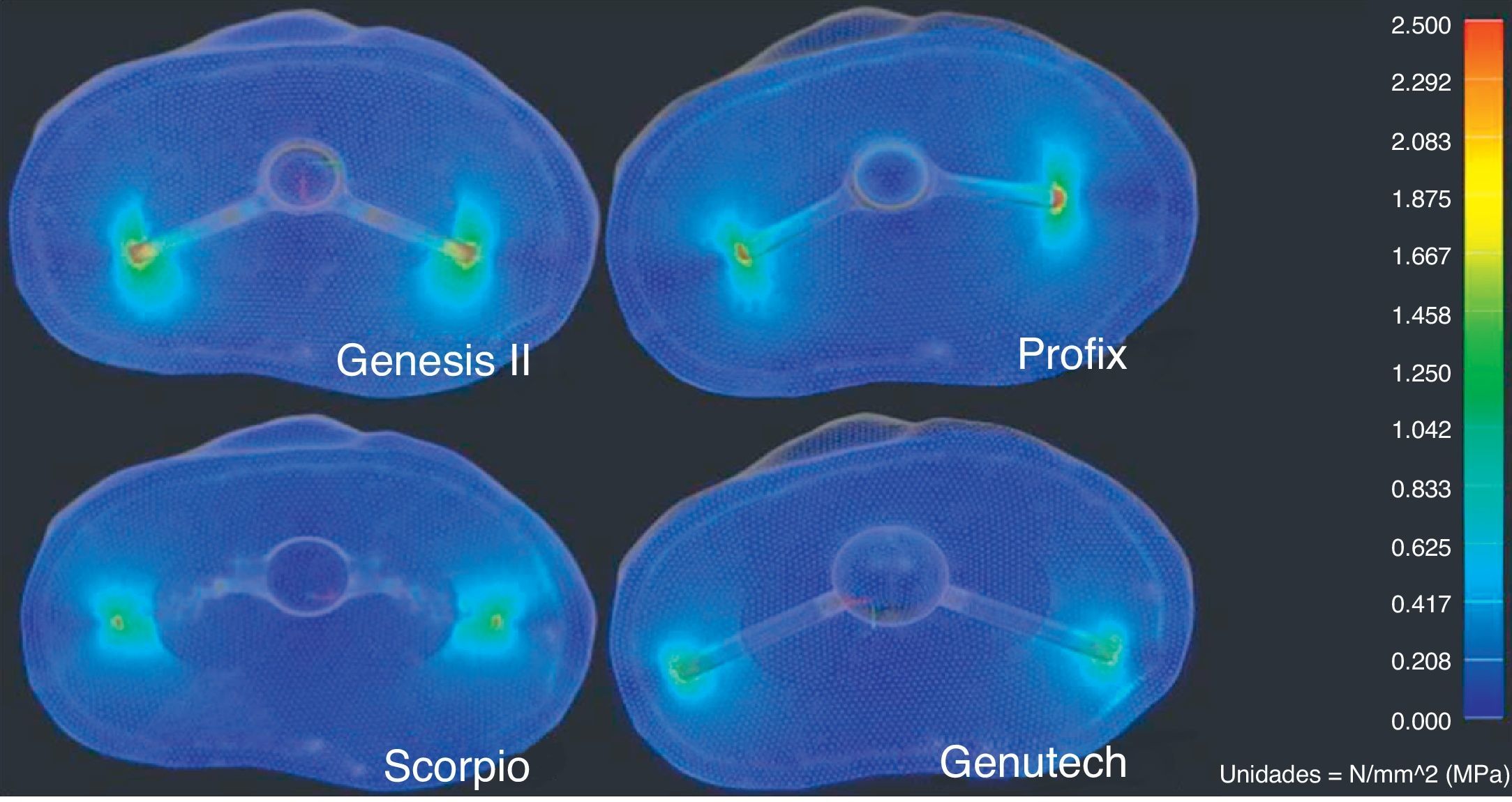
We modelled 4 tibial trays, made of a titanium alloy, with different primitive geometry of the keel (Fig. 3). The first 2 corresponded to the GENESIS II and PROFIX models (Smith and Nephew, Inc., Memphis, US), whilst the third was the SCORPIO model (Stryker 4100, Kalamazoo, US). Lastly, we used the GENUTECH® model (Surgival, Valencia, Spain) (Fig. 4). We selected the best size in each model corresponding to the size of tibia generated. The size of each implant corresponded to an approximate mediolateral length of 75mm; the medium lengths between the opposite ends of the keels were: SCORPIO: 50mm, PROFIX: 44mm, GENESIS: 48mm, GENUTECH®: 60mm. The tibial tray was placed following a standard positioning (1/3 with respect to the anterior tibial tuberosity) (Fig. 5).2–5

 tibial tray.")
 tibial tray regarding the anterior tibial tuberosity.")
We placed the implant by subtracting from the coinciding volumes once the tibial component was positioned. We did not include bone cement in the model. We forced the union between the blades of the implant and the bone, leaving the central axis and the superior part free. The different portions of the bone were joined together.
The study by finite elements was conducted through the recreation of the surrounding conditions and torque load for each of the tibial trays in a homogeneous manner (position and orientation of the tibial tray), in order to make the study reproducible for all the models.
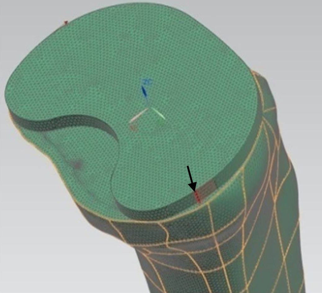
For the mechanical simulation we used the software programme Unigraphics NX 8.5 (Siemens PLM Software, Corporate Headquarters Siemens, Munich, Germany) with a Nastran calculation engine. For the generation of the bodies we used hexahedral-type elements with 10 nodes and a maximum ridge size of 1mm. We applied a torque of 6 Nm (Fig. 6) to the model, placing the most medial and lateral ridges of the tibial component2 (according to ISO 14243-1:2003). We restricted the movement and turns of the nodes of the external surface of the cortical bone to compare the index of tension only in the trabecular area.
 tibial tray. The image shows the direction in which the torque is applied (arrow).")
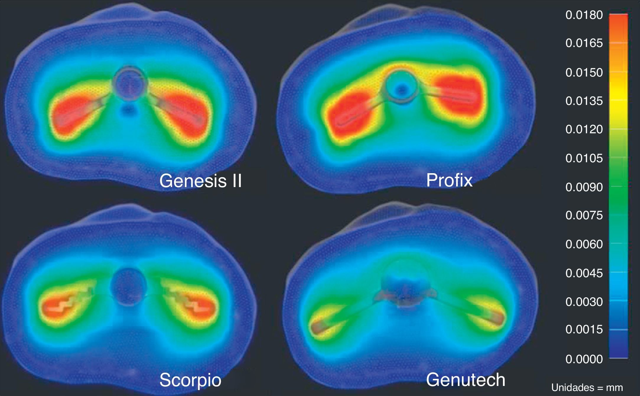
We analyzed the results of the total displacements (Fig. 7), as well as the results obtained from the von Misses tensions (Fig. 8) and the maximum traction and cutting tensions.
Results

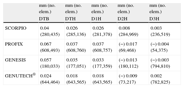
The results of the study are represented in Table 2 and show that the GENUTECH® tibial tray enabled a load distribution which was localized in the most external peripheral trabecular bone and a larger trabecular area.
Results of displacements in mm and node of the mesh where it takes place.
| mm (no. elem.) | mm (no. elem.) | mm (no. elem.) | mm (no. elem.) | mm (no. elem.) | |
| DTB | DTH | D1H | D2H | D3H | |
| SCORPIO | 0.04 (280,435) | 0.026 (285,136) | 0.026 (281,378) | 0.008 (284,969) | 0.003 (236,519) |
| PROFIX | 0.067 (608,493) | 0.037 (608,760) | 0.037 (608,757) | (−) 0.017 (69,468) | (−) 0.004 (54,375) |
| GENESIS | 0.057 (180,033) | 0.035 (177,051) | 0.033 (177,359) | (−) 0.013 (180,112) | (−) 0.003 (794,810) |
| GENUTECH® | 0.024 (644,464) | 0.018 (643,565) | 0.018 (643,565) | (−) 0.009 (73,217) | 0.002 (782,825) |
DTB: maximum displacement on the tibial tray; DTH: maximum displacement on the bone structures; D1H: maximum displacement in direction 1 produced on bone structures; D2H: maximum displacement in direction 2 produced on bone structures; D3H: maximum displacement in direction 3 produced on bone structures.
The greatest displacements produced on the proximal tibia by this simulation were observed in the anteroposterior direction. The results reflect less bone displacement transmitted by the GENUTECH® implant.
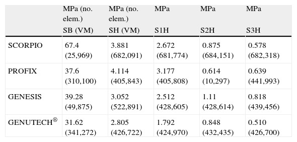
Regarding the resulting tensions, according to the criteria by von Misses (Table 3), the GENUTECH® implant had the lowest resulting tension levels.
Results of tensions in MPa and node of the mesh where it takes place.
| MPa (no. elem.) | MPa (no. elem.) | MPa | MPa | MPa | |
| SB (VM) | SH (VM) | S1H | S2H | S3H | |
| SCORPIO | 67.4 (25,969) | 3.881 (682,091) | 2.672 (681,774) | 0.875 (684,151) | 0.578 (682,318) |
| PROFIX | 37.6 (310,100) | 4.114 (405,843) | 3.177 (405,808) | 0.614 (10,297) | 0.639 (441,993) |
| GENESIS | 39.28 (49,875) | 3.052 (522,891) | 2.512 (428,605) | 1.11 (428,614) | 0.818 (439,456) |
| GENUTECH® | 31.62 (341,272) | 2.805 (426,722) | 1.792 (424,970) | 0.848 (432,435) | 0.510 (426,700) |
DTH: von Misses tension produced on bone structures; SB: von Misses tension produced on the tibial tray; S1H: maximum main tension in direction 1 produced on the bone structures; S2H: maximum main tension in direction 2 produced on the bone structures; S3H: maximum main tension in direction 3 produced on the bone structures.
The present study confirms that tibial trays with different keel geometries transmit torsion forces differently. The GENUTECH® tibial tray model has been found to have less displacement and lower tension levels in the transfer to bone.
The main loads produced when walking take place at the axial level, coinciding with the direction with the best mechanical behaviour of the tibia. However, the efforts produced by anteroposterior and torsion loads, combined with the axial, are the cause of the main tensions in the transversal plane of the tibia.1
The design of the tibial tray is a very important factor which affects the transmission of loads. The transmission of excessive loads could produce excessive effort in the periprosthetic area and cause a collapse of the bone volume containing it.1 On the other hand, the absence of transmission of efforts may induce a decrease of the mechanical properties of the affected bone area.2,5,10
For these reasons, it is important to take into account several biomechanical factors when designing a tibial component:
- –
The level and distribution of implant–bone loads.
- –
The resistance of the prosthetic components.
- –
The resistance of the adjacent bone.
Torsion efforts generate cutting efforts in the transversal plane of the implant–bone union which can cause aseptic loosening of the implants. Despite the existing bibliography on studies by finite elements of tibial trays,11,12 there is no consensus on which implant models offer better clinical results.
It has been proven that the bone structures of the proximal tibia have greater resistance in the periphery8,9; therefore, it seems logical to think that those designs which carry their loads to these areas will afford a more efficient transmission of tensions. Nevertheless, we have not been able to find references which confirm this point, so the present study seems to be the first conducted along those lines.
The results obtained in the present study reflect the fact that the design of the GENUTECH® tibial tray offers the least displacement and transmits the least load to the bone. Moreover, when we observe the location of the maximum tension levels, we can see that they appear in the areas where the bone offers its best mechanical properties. Thus, with equal torque, the GENUTECH® tibial tray should, theoretically, offer a lower probability of suffering loosening.
The cornerstone of this study is the mechanical concept of moment of inertia, which is defined as “resistance presented by a body to rotate about any of its main axes”. The moment of inertia is influenced by the geometry of a body. Specifically, in the case of the studied tibial trays, the factors which influence the moment of inertia are: the length of the arms of the keels (those with a longer length offered a greater moment of inertia) and the section resisting rotation. Keels with rectangular sections, as in the PROFIX and GENUTECH® models, are more efficient than those with triangular sections, such as the GENESIS II and SCORPIO models. Furthermore, among the most efficient models (rectangular section), those which concentrate a greater section in the most external tibial part are more effective at dissipating tension since having a greater contact area enables a more homogeneous and less concentrated distribution of loads.
We conducted several finite element studies of the tibial tray models mentioned previously in order to determine the distribution of tensions on the tibia.2–4 In these cases, we assessed various aspects, such as support and geometry of the tibial stem. The conclusions seemed to indicate that a correct placement and a maximum contact surface between the tray and bone minimized tensions. This is one of the aspects gathered in our study, but applied to the geometry of the keel and its contact with the bone.
Bone is very resistant to compression loads but not that much to traction and cutting loads.8,9 The GENUTECH® tibial tray has been shown to promote the distribution of traction and cutting loads in the transversal plane, which is better suited to torsion efforts.
There is no consensus on the mechanical characterization of the bone of the proximal tibia. Nevertheless, several studies have confirmed that trabecular bone areas close to the cortical are more resistant than other and more central parts.8,9
The main limitation of the study is that, since the objective of the analysis was to identify the behaviour of the tibial tray under torsion loads, the results cannot be directly extrapolated to the clinical performance of the implant in vivo. Neither have we examined the possibility of a cemented implant, a very frequent situation in clinical practice. Nevertheless, we would not expect to observe considerable differences in behaviour, as the cemented area is generally the lower part of the tibial tray. Lastly, another limitation of the present model also worth mentioning was being based on bibliographic data on bone densities and their mechanical properties.8,9 Anatomical tibial reconstruction, which was subsequently categorized through bibliographic data, may not correspond exactly to each specific situation.
The results obtained indicate that the tibial tray with more peripheral support has a better performance under torsion forces. Further biomechanical studies would be required in order to assess keel designs against various load conditions taking place on the tibial tray, and to gauge the effect of cement.
Evidence levelEvidence level IV.
Ethical disclosuresProtection of human and animal subjectsThe authors declare that no experiments were performed on humans or animals for this study.
Confidentiality of dataThe authors declare that no patient data appear in this article.
Right to privacy and informed consentThe authors declare that no patient data appear in this article.
Conflict of interestsSergio García, José Ángel Cortijo and Iván Navarro are employees of the R&D Department of Surgival. Francisco Maculé, Pedro Hinarejos, Lluís Puig-Verdié, Joan Carles Monllau and José Antonio Hernández Hermoso are scientific consultants for Surgival.
Please cite this article as: García David S, Cortijo Martínez JA, Navarro Bermúdez I, Maculé F, Hinarejos P, Puig-Verdié L, et al. La geometría de la quilla condiciona el comportamiento de la bandeja tibial frente a fuerzas de torsión en prótesis totales de rodilla. Rev Esp Cir Ortop Traumatol. 2014;58:329–335.
