


Plasma electrolyte oxidation was used to modify the surface of different Ti alloys: c.p. Ti (α hcp structure), Ti–15Nb (α′+β structure) and Ti–33Nb–33Zr (stable β cubic structure) and the influence of elements and microstructure in the TiO2-based ceramic layer formed as well as the surface properties was analyzed. The XRD patterns confirmed the presence of TiO2 (anatase and rutile) in the c.p. Ti. For Ti–15Nb (wt.%) indicated the presence the same oxides also of pentoxide niobium (Nb2O5). For Ti–33Nb–33Zr (wt.%) indicated just the presence of rutile as the stable oxide one at room temperature and dioxide zirconium (ZrO2). In addition, the formation of calcium carbonate CaCO3 and calcium phosphate Ca3(PO4)2 was detected in all 3 materials. The ceramic-like layer was more homogeneous for c.p. Ti and Ti–15Nb and more irregular hole like-pores for Ti–33Nb–33Zr. Bioactive ions used were detected in all alloys and the roughness for Ti–15Nb was higher compared to c.p. Ti. and Ti–33Nb–33Zr. The contact angle for the three samples was higher than 100°.
La electro oxidación por plasma fue utilizada con el objetivo de sintetizar recubrimientos de óxidos en la superficie de diferentes aleaciones de Ti tales como: Ti c.p. (estructura α hcp), Ti-15Nb (estructura α′+β) y Ti-33Nb-33Zr (estructura cúbica β estable). Así mismo, esta técnica permitió evaluar el efecto de los elementos de la aleación; la microestructura de la capa cerámica formada, cuya base es TiO2; así como las propiedades superficiales. Los patrones de XRD confirmaron la presencia de TiO2 (anatasa y rutilo) en el Ti c.p., así como la presencia de los mismos para la aleación Ti-15Nb (% en peso) y la formación del pentóxido de niobio (Nb2O5), mientras que para la aleación Ti-33Nb-33Zr (% en peso), el análisis de DRX mostró la presencia del rutilo, como el óxido estable a la temperatura ambiente, así como del dióxido de zirconio (ZrO2). Además, en los 3 materiales se detectó la formación del carbonato de calcio CaCO3 y fosfato de calcio Ca3(PO4)2. Adicionalmente, la capa cerámica fue más homogénea para el Ti c.p. y Ti-15Nb, mientras que los microporos formados fueron más irregulares en la aleación Ti-33Nb-33Zr. Los iones bioactivos utilizados se detectaron en todas las aleaciones. Sin embargo, la rugosidad para el Ti-15Nb fue mayor en comparación con la del Ti c.p. y Ti-33Nb-33Zr, aun cuando el ángulo de contacto para las tres muestras fue superior a 100° indicando una superficie más hidrofóbica.
The surface has an essential function in the reaction of the biological environment with the implant. If surface topography [1], porosity, chemical composition, are in suitable ranges, the osseointegration process will occur [2]. The main problem found to guarantee the excellent osseointegration is because the surface material is bio-inertness being difficult to create surface oxide on titanium alloys and leading to slow bone cell adhesion to the implant compared to bioactive materials [3]. The bioactive surface of Ti and its alloys depend specifically of the alloy elements, microstructure, such as grain size, phase composition, morphology and chemistry of its surface layers [4,5]. Therefore, suitable parameters adjustment on surface modification and the specific techniques could improve the biocompatibility and fast osseointegration process. The mainly techniques based on coatings treatment to create biologically active surfaces are: ion implantation, laser surface treatment, electrodeposition [6–8], physical vapor deposition [9] and anodic oxidation by plasma electrolytic oxidation (PEO). Recently, PEO has been successfully used to create a micropores pattern applied to titanium alloys [10]. Porous surface of the titanium can promote the adhesion and proliferation of bone cells [11] and more than that, can create a better mechanical fixation to the surrounding tissue [12]. PEO has appeared as a breakthrough electrochemical method to produce metal-oxide-based films with customized features on the surface of valve metals, such as Ti [13–15]. This is an electrochemical procedure that induces to the development of a ceramic-like film on materials surface, generally characterized by high thickness, providing wear and some corrosion resistance. PEO is an easy, rapid and versatile method to treat surface metals of variable size and geometry also, is recognized as ecologically friendly, thus becoming very appealing to be used for industrial applications [16].
Besides is characterized by the phenomenon of electrical discharge on the metal that acts as an anode immersed in an electrolyte at the potentials above the spark voltage of the coating [17].
The oxide film exhibits a variety of different properties that depend on the alloy elements of the material as well as the electrolyte, processing parameters, such as anode potential, electrolyte composition, temperature, and current density [18]. Thick, porous and well-adhered TiO2 oxide films may be successfully grown in the surface of biomedical metallic implants with multifaceted geometries, such as dental or orthopedic implants made out of titanium and titanium alloys [19,20]. The electrochemical immersion used for PEO processes may be supplemented with bioactive ions such as calcium (Ca), phosphorous (P), and magnesium (Mg) aiming their incorporation into the anodic films during electrochemical reactions that take place during the processes, accompanied by the conversion of the metal surface into titanium oxide. The addition of these elements in the electrolyte and consequent enrichment of PEO films with them, may provide not only excellent corrosion protection and enhanced tribological properties [21], but also can improve the osseointegration properties of the materials when applied in the orthopedic filed.
The alloys based on system Ti–Nb–(Zr) are very interesting due to some excellent mechanical, biological and electrochemical properties for medical application field. Zr is an element that belongs to the same group as Ti in the periodic table, presenting similar chemical properties [22]. Zr acts as a strong hardening agent for the solid solution [23] and is easy to form solid solutions with Ti, which is added to improve mechanical and corrosion resistance as well as the biocompatibility [24]. Adding Zr can also decrease the martensitic transformation temperature (Ms) of the α′ phase and slightly decrease the alloy's melting temperature [25,26].
On the other hand, Nb is important β stabilizer which has been frequently used in traditional α+β systems and high strength metastable β titanium alloys [27–29].
The present work will show significant differences among three Ti alloys (commercial pure Ti (CP-Ti), Ti–15Nb (α′+β phases) and Ti–33Nb–33Zr (β stable alloy) namely: CP-Ti, TN15 and TNZ33, that are formed for different microstructure, phase and chemical composition in the influence of ceramic-like film formation during the PEO coating.
Experimental procedureSynthesis of as-cast samples and PEO preparationAn arc melting furnace with a non-consumable tungsten electrode on a water-cooled copper hearth (Edmund Bulher model D-72411) was used to melt the CP-Ti, Ti–15Nb and Ti–33Nb–33Zr (wt%) samples under an ultra-high purity argon atmosphere. Before the melting process, the raw materials were prepared by cutting them to the applicable sizes and subsequently weighing them according to the calculation of material balance, and loading them onto the top of a copper crucible in the melting chamber. The melting process took place under vacuum that is achieved by pumping the chamber up to the vacuum condition (10−5mbar) and subsequently draining it by argon, so that the melting chamber is free of oxygen. The ingots were re-melted eight times to ensure the process had undergone completion rather than to improve their chemical homogeneity. For PEO preparation cuts of 1mm were made in the cross section of the samples using a high-speed cutter (Isomet 5000-buehler). Hereafter were subjected to griding up to # 600 mesh of sandpaper to have the same roughness pattern for all samples surfaces before the PEO process. The samples were cleaned with distilled water and ethyl alcohol/acetone for 1h in an ultrasonic bath.
For the PEO bath, was used an electrolyte solution formed by calcium acetate hydrate, β-glycerophosphate and magnesium acetate tetrahydrate at a molar concentration of 0.35M, 0, 02M and 0.1M. The bath was homogenized at room temperature in a magnetic stirrer until all components are dissolved. The Pt electrode was used as reference (as cathode) and the sample as anode. The time of the process was of 1min and was made by galvanostatic method, keeping the current 2.5A and for current recording, an Agilent digital bench multimeter, flexible cables, and a computer were used to record the records. Electrochemical curves (current vs time) of the three samples can be shown in Fig. 1 and indicates the evolution of current during the PEO process. The three curves showed two main stages during the ceramic growth layer. In Fig. 1b it is possible no note in more details the galvanostatic control, limiting the current at 2.5A. This stage corresponds to the traditional anodizing process. Then, when the potential exceeds a specific critical value, the dielectric barrier of the ceramic layer starts to broken at vulnerable spots, leading to appearance of several sparks over the surface. The current flow starts to concentrate at the sparking locations, triggering local thickening of the coating. As the potential is increased with time, those sparks transform into highly energetic micro-arcs. The central second stage is started when the potential reaches the set value (300V). In this moment the potentiostatic control takes place, resulting in the decrease of current and reducing the number of micro-arcs at the surface.
Structural and microstructural characterization of PEO surface of as-cast samples
The structural characterization (identification of the present phases) of the bulk and the coating layer were made using X-ray diffractometer with Cu Kα radiation (Bruker-D8 Advance ECO) operating with 0.05 steps at the angles where the diffraction peaks were wider and 0.02 degrees for narrower peaks. Counting times per step were in the order of 10s. For the identification of crystallographic peaks pattern, the Inorganic Crystal Structure Database (ICSD) was used to match to the experimental ones. Morphological analyzes and elemental distribution (Ti, Nb, Zr, Mg, Ca and P) were performed using a Scanning Electron Microscope (SEM, from Philip XL-30 FEG), equipped with a Secondary Electron detector, Backscattered Electrons and X-ray Dispersive Energy (EDS).
Thickness and porosity of the coating layer formed after PEOTo analyze the thickness of the layer, the cross-sectional zone of the samples was prepared (grinded and polished) and they were evaluated by SEM analyze. The porosity of the coating layer was determined by analyzing the images obtained by SEM using the software Image J®.
Evaluation of the roughness coating layer after PEOThe roughness pattern and homogeneity of the microporosity layer formed was studied using an instrument that was used for measuring surface roughness (Olympus LEXT OLS 4000), combining three optical technologies, confocal, interferometric and focus variation. The samples were placed one at a time under the microscope in laboratory conditions (normal pressure, room temperature 25°C, relative humidity 60%). Their observation was carried out with 40× objective. The light source used was the green LED (530nm), while a brightfield objective and the confocal mode were employed. All three samples were measured by taking images of their surface and data concerning their topography, dimensions and their parameter. The roughness was evaluated considering three measures of the absolute average relative to the base length (Ra) parameter.
Wettability and free energy of coating layer formed after PEOThe analyses of wettability and free energy was based on sessile drop technique. Experiments were carried out at 37°C. Three analyses were performed per sample. The values were represented using media and standard deviation.
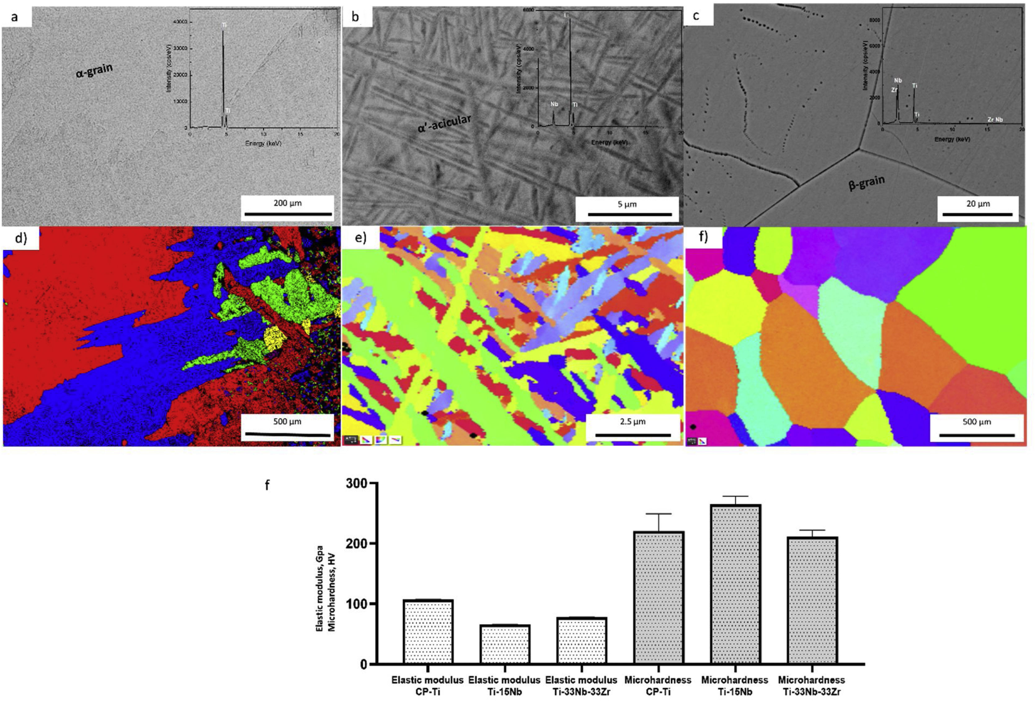
ResultsCharacterization of as-cast Ti–15Nb and Ti–33Nb–33Zr before electrochemical treatmentThe microstructural and mechanical properties information of as-cast CP-Ti, TN15 and TNZ33 are indicated in Fig. 2a–f. The CP-Ti sample was formed by large equiaxed α-grains, with average grain size (GS) approximately 500μm (Fig. 2a and d) and the TN-15 alloy was formed by heterogeneous and millimetric acicular grains. Increasing the β stabilizer content Nb to 33wt%, the grain size (GS) visibly increased with more homogeneous distribution changing its morphology to equiaxed ones. According to mechanical properties, the as-cast TN15 alloy, presented microhardness and elastic properties lower compared to TNZ33 (Moeq of 21.1wt%). In a recent work reported by dos Santos et al., the TN15 samples were formed by a heterogeneous microstructure (α+β phases), with an average GS of 1.29μm and an Moeq of 4.95wt% [30]. Introducing Zr as a neutral element, mechanical properties increased. Also, it is possible to note that the GS of the microstructure is higher compared to the TN15 alloy, which can increase the mechanical properties (Fig. 2f). So, the next results presented in this work will discuss based on the chemical composition of these samples as well as their microstructure.
, TN15 (b, e) and TNZ33 (c, f); elastic modulus, E (GPa) and microhardness (HV) values, for CP-Ti, TN15 and TNZ33 bulk samples (g).")
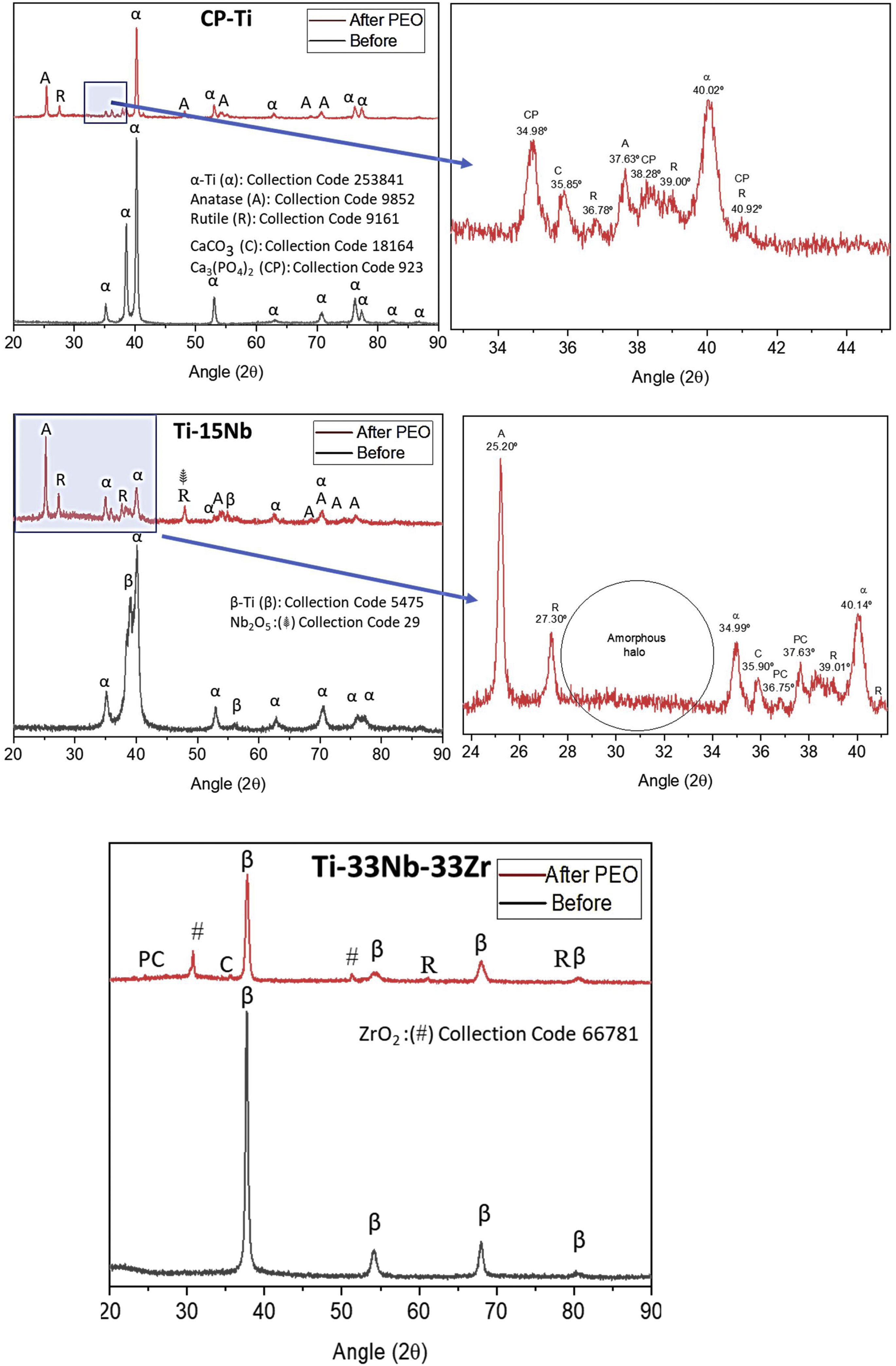
Fig. 3 shows XRD profiles of as-cast samples before and after PEO coating. The as-cast CP-Ti samples as expected was structured under hcp and after the PEO treatment it is possible to note the presence of anatase (metastable) and rutile (stable) Ti dioxide under tetragonal structure as well as the presence of CaCO3 and Ca3 (PO4)2. For the as-cast TN-15 samples, the XRD pattern showed the presence of two phases, being them β-Ti (less quantity) and α-prime-Ti (more quantity). After the PEO coating, the XRD pattern indicates the presence of the same oxides founded in CP-Ti and also the Nb2O5 (monoclinic) at the 48°. It is possible to note, the amorphous halo formed between 2θ=28–34°.

Increasing the alloy element content for 33wt% of Nb and Zr the β phase was stabilized as shown in its profile XRD and the anatase peaks were not found, just the rutile, ZrO2 (tetragonal) at the 54° and the CaCO3 oxides.
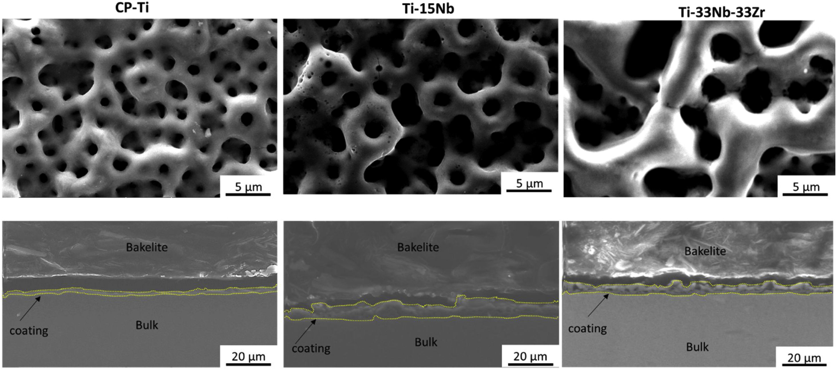
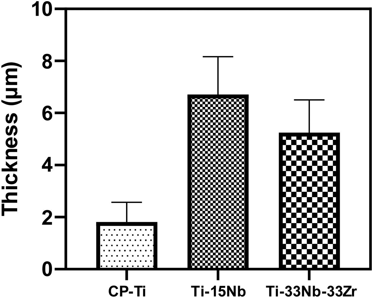
Morphology of the layer formation on different types of Ti samples are indicated in SEM images in Fig. 4. The CP-Ti samples presented a good homogeneous pores layer and no cracks was found. For TN15 alloy the same morphology was found, but the pore size increased and some cracks can be found. Differently for TNZ33 alloy, the morphology of the layer formed was distinct to the first ones. Elongated microholes mixed with micropores were created forming lesser regular morphology. Comparing the thickness of the surface barrier layer of the samples, the TN15 presented higher value followed by TNZ33 and CP-Ti indicated in Figs. 4 and 5.


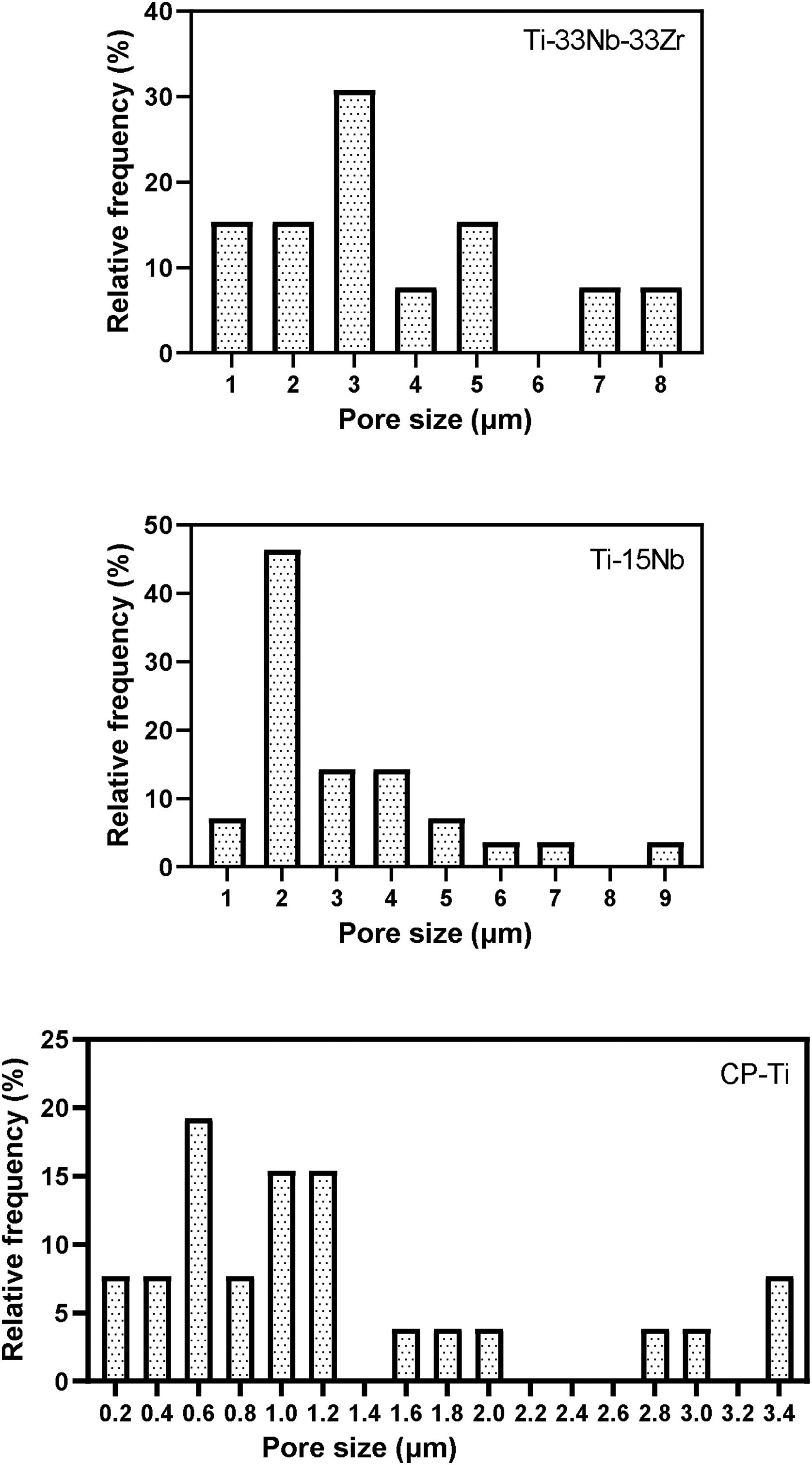
In Fig. 6 are indicated the relative frequency distribution of micropores found on layer surface of the samples. The CP-Ti sample is formed basically by micropores in the range of 0.2–3.4μm. Adding Nb content, the range size increased to 1–9μm for TN15 and 1–8μm for TNZ33 alloys. It is possible to note that the distribution of pores of Ti–15Nb follows a Gaussian distribution different of the CP-Ti and TNZ33 which can be characterized as more random. The size of pores was different depend on the alloy composition. Add Nb the pore size increase from 0.2 to 1μm. Increase the Nb content and Zr on the Ti the porous pattern was more heterogenous.
SEM and EDS evaluation
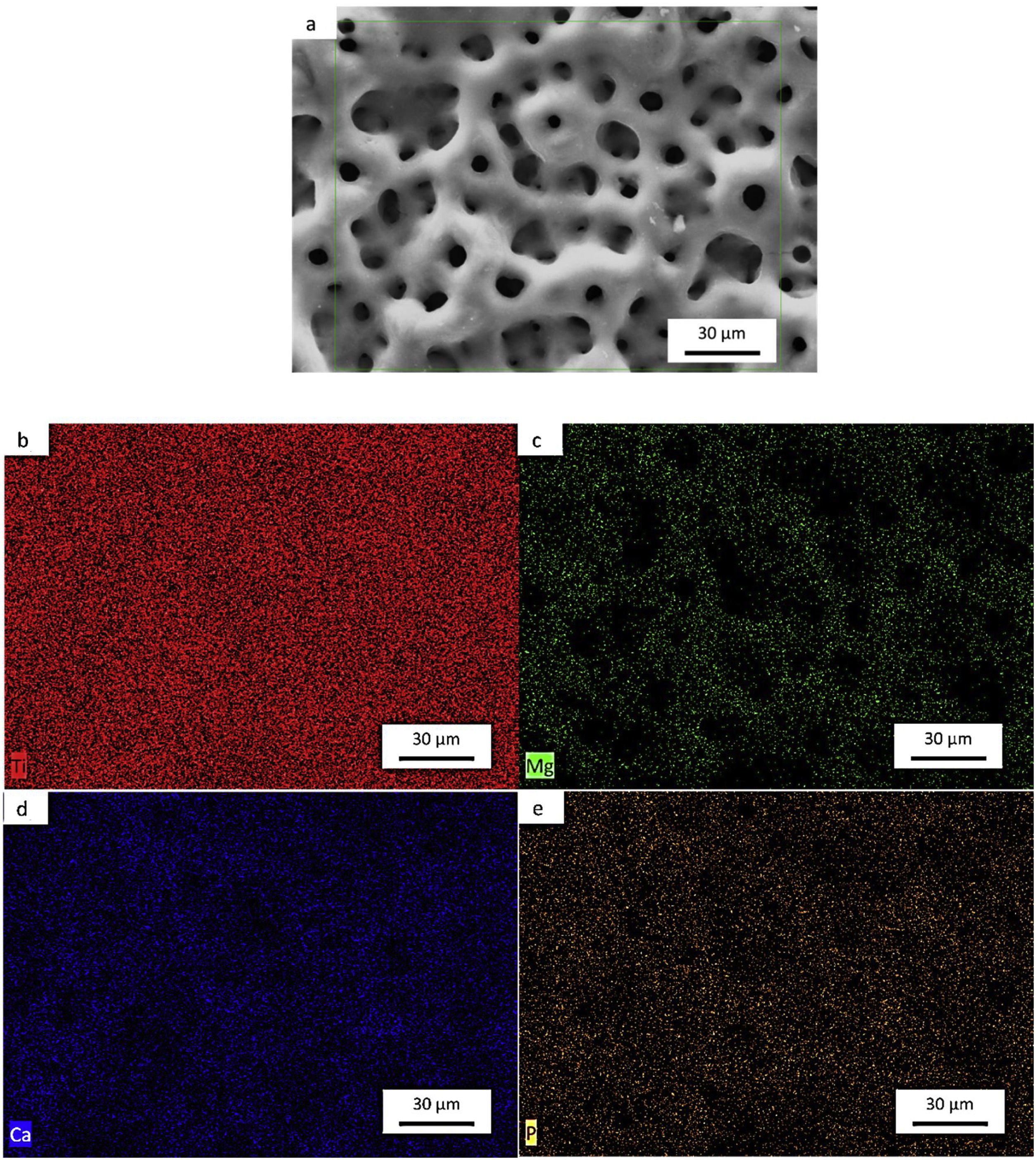
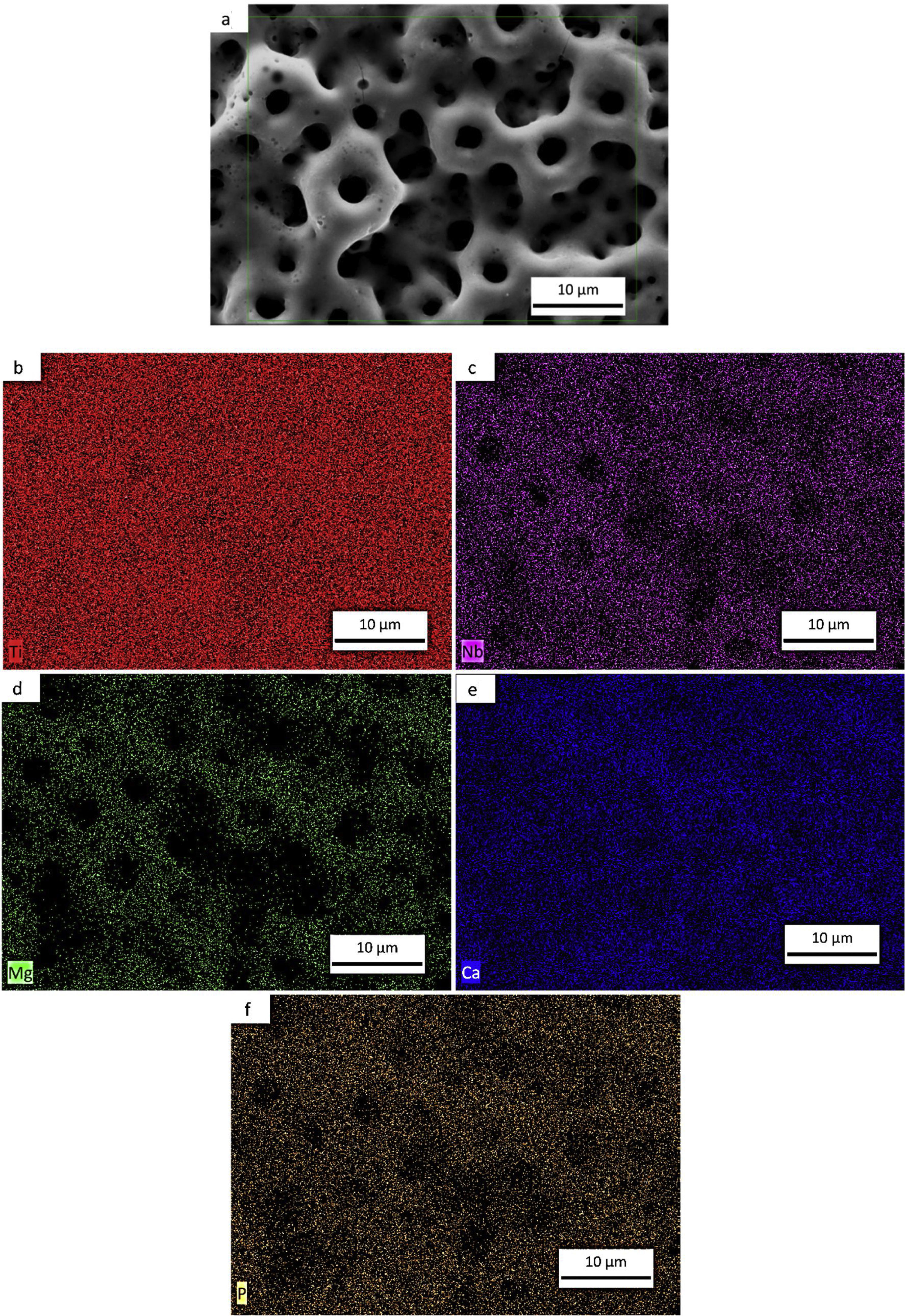
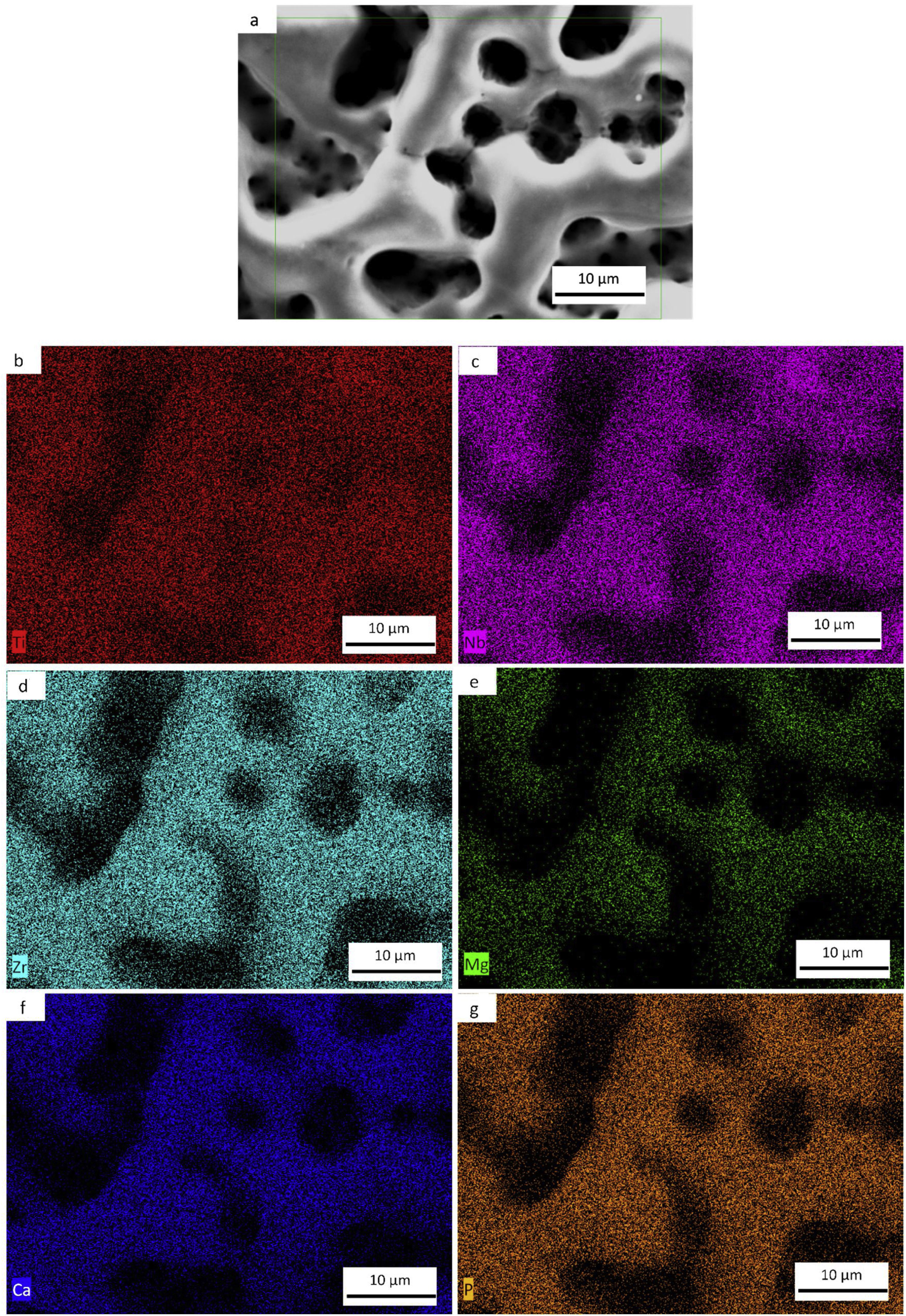
Figs. 7a–e, 8a–f and 9a–g shows the micrographs obtained by a backscattered electron detector of the microstructure and morphology micropores of the samples after PEO treatment. The microstructure consists of presence of Ti in all samples, as well as Nb and Zr for the Ti alloys showed by the elemental mapping in Figs. 7b, 8b, c and 9c, d. The three elements present a good distribution and homogeneity. For all samples it is possible to note that the Mg, Ca and P elements were incorporated on the microstructure seen in Figs. 7c, 8d–f and 9e–g. The incorporation of the three elements is accompanied the Ti and Nb elements and no preference was found.
 SEM of CP-Ti. (b)–(e) map distribution of Ti, Mg, Ca and P elements.")
 SEM of TN15. (b)–(f) map distribution of Ti, Nb, Mg and Ca and P elements.")
 SEM of TNZ33. (b)–(g) map distribution of Ti, Nb, Zr, Mg, Ca and P elements.")
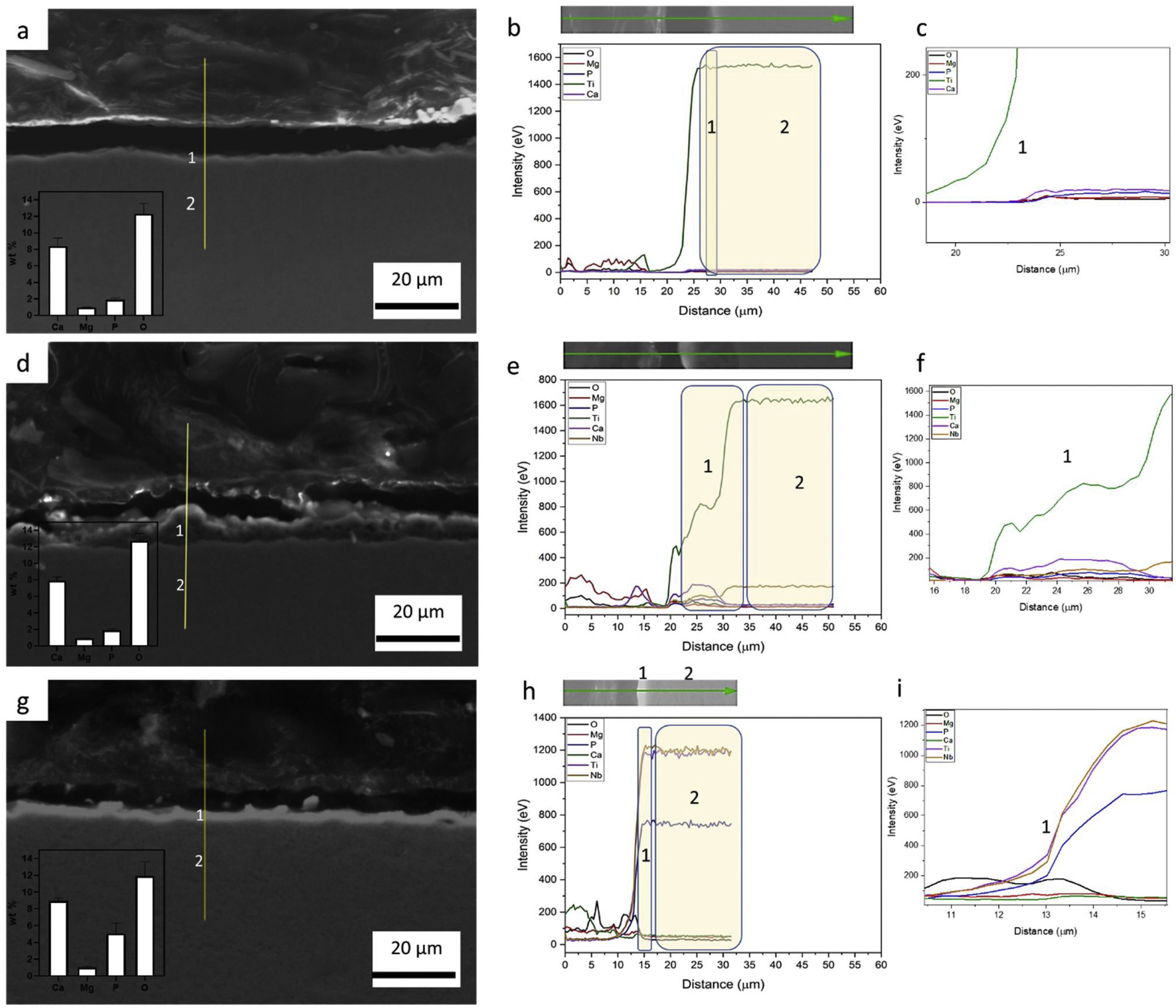
Influence of alloy elements on segregation of Ca, Mg and P bioactive elements was analyzed using linescan method in SEM analyses. The results can be found in Fig. 10. The linescan of CP-Ti also its SEM image referent to the linescan image (Fig. 10a–c)) showed two specific regions namely 1 and 2. According to the linescan direction, it is possible to note that in region 1 (barrier layer) there is high Ti intensity and low Mg, P, Ti, Ca and O intensities, close to zero. The same happens in the region 2 where Ti intensity is higher and no segregation of bioactive elements can be found. In more details, a zoom of the region 1 can be found in the second graph (Fig. 10c). It is possible see that the bioactive elements present a constant distribution over the microstructure, presenting a little increase close to 23μm of the linescan. For TN-15 alloy, two regions as the CP-Ti sample can be found (Fig. 10d–f). Differently of the first one, the region 1 (porous layer) presented high concentration of Ti, followed by Ca and Nb. The other elements, P and Mg presented a constant and small concentration. These characteristics are better indicated at the second curve plotted in Fig. 10f). Then, enter to the microstructure (region 2) of the TN15, the Ti and Nb elements present constant and linear distribution and the bioactive elements decrease their intensities. In the TNZ33 alloy, are indicated also two regions in The SEM image (Fig. 10g–i) and the distribution of the elements in the linescan can be seen in the both curves in Fig. 10h and i). First, in the region 1 (barrier layer) is formed by all the elements and different from the other ones, P element is accompanied with the Ti and Nb and its segregation was significantly higher (2wt% on CP-Ti and TN-15 surfaces and 5wt% on TNZ33 surface) than found on CP-Ti and TN-15 samples, through EDS analysis. The others bioactive elements present a linear and small distribution as can be seen.
Roughness profile, wettability and surface energy of the as-cast Ti samples after PEO treatment, CP-Ti, (b), TN15, and (c) TNZ33 using EDS and BSE detector. All images were obtained with a 1000× of magnification.")
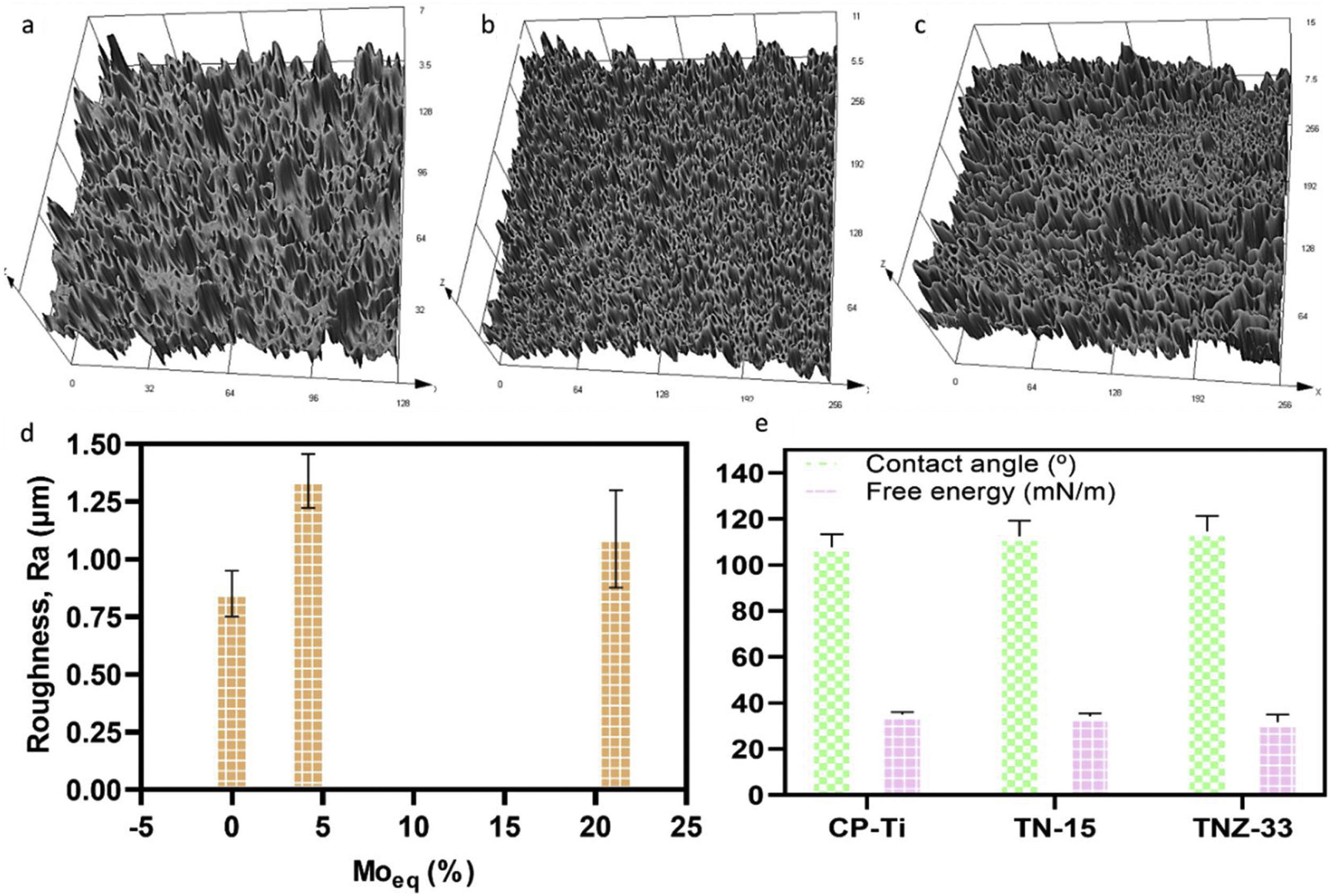
The profile roughness of different as-cast Ti samples and the quantitative values of them based of the Ra parameter are indicated in Fig. 11a–d. According to the confocal microscopy images the roughness profile of the CP-Ti and TN15 samples are more uniform compare to the TNZ33. The maximum Z value was found in TN15 followed by CP-Ti and TNZ33. The higher Z value represent the maximum height of the peak found during the image scanning and not the average of roughness. In order to evaluate the quantitative roughness of each sample the Ra parameter was taken into account. As observed, according to Fig. 10 TN15 showed higher roughness followed by TNZ33 and CP-Ti following the same tendency of range of pores and thickness of the barrier and porous layer formed.
, (b), and (d). Contact angle and free energy of pores layer formed during PEO process, (e).")
The wettability of the ceramic layer formed based on different Ti alloys was evaluated by measure of contact angle (CA) and surface free energy (SFE). The CA of three samples were close and were in the range of 107–112° (hydrophobic surfaces) and free energy in the range of 31–35mN/m. The contact angle and free energy were inversely proportional which is in accordance to others results already reported. There was no significative difference among the contact angle and free energy surface on the ceramic layer formed.
DiscussionThe addition of a β stabilizing element, which are refractory metals such as Nb, Ta and Mo with high melting point, requires high energy to form oxides of these elements on the surface of Ti alloys. From the potential used (300V) and consequently the temperature produced by the arc was not enough to crystallize the oxides formed on the TN-15 alloy, due to formation of amorphous halo in the XRD profile in Fig. 3. Unlike the TNZ33 alloy, the Zr element is very reactive with oxygen, making it easier for the formation of the oxide layer, requiring low energies for the crystallization and phase transformation of the oxides on the ceramic layer. According to literature, the standard Gibbs free energy for metallic oxidation of ZrO2 reaction value is −1080kJ/mol, while TiO2 reaction value is −945kJ/mol [31,32].
In the work reported to Correa et al. the Ti–15Zr–xMo system presented variation in the crystallinity of the oxides according to the chemical composition of the alloy. For the Ti–15Zr–5Mo, a biphasic alloy formed by α two prime and β phases, showed the presence of anatase, rutile, ZrO2 and amorphous layer confirmed by TEM analysis [33], being in agreement to the results found in this work.
This could be due to the greater ease of the short-range ordered TiO6 octahedra in arranging into long-range ordered anatase structure owing to the less-constrained molecular construction of anatase relative to rutile [34]. On the other hand, the more rapid recrystallisation of anatase could be due to the lower surface free energy of this polymorph, despite the lower Gibbs free energy of rutile [35]. That is, the higher surface free energy of rutile crystallites may favor the crystallization of anatase.
For TNZ33 samples, no anatase peaks was found in XRD profile and was possible to form just rutile under near room temperature conditions, being in accordance to literature, where rutile nanorods was formed under near room temperature conditions [36]. The main factors that can influence the anatase→rutile phase transformation can be related to its kinetics of temperature time conditions and chemical composition of the alloys. As both samples were treated at the same environment conditions, the amount of Nb, Zr or the β phase present in the TNZ33 could increase the kinetics of the phase transformation to rutile oxides.
In Figs. 4 and 5 are shown the morphology and thickness of the ceramic layer formed on different Ti samples. The irregular thickness formed on TNZ-33 samples can be related to insufficient fusion during the PEO deposition through the excessive ion concentration on specific areas leads to the PEO reaction front to enter the spark discharge stage, making the number or the size of gap/crack inside of the PEO coating to increase and thus ending up with an irregular layer formation.
The alloy composition can influence not only the morphology of ceramic layer, but also the porous growth during the PEO treatment. Zr is an element more reactive than Ti and Nb. In this case, during the electrochemical process, it could react with oxygen, increasing the temperature by the high potential applied (300V) and consequently the sparks on surface also increase, creating more available ions. This characteristic of reactivity can contribute to the irregular growth of ceramic porous layer on the metallic substrate, also seen on the irregular thickness of the ceramic layer formation.
It is visible that the alloy elements and the microstructure can influence the oxides formation but also the thickness of the barrier layer once the main differences between samples are the phases and Nb and Zr content.
TN15 alloy presented a biphasic microstructure (more heterogenous) and the presence of Nb as alloy element. During the PEO was formed further the dioxide Ti also niobium pentoxide. According to literature it is the most stable oxidation state of the niobium–oxygen system, niobium pentoxide (amorphous or crystalline) [37]. Besides, according to news reports, the pentoxide niobium indicated a uniform layer formed also related to the higher specific area [37].
In the biomedical field, as more regular and bigger the pores are better tensions force can be distributed promoting good mechanical fixation and strength [38]. Besides, there are more space for the new bone tissue ingrowth [39].
The roughness of the ceramic layer was represented according to the Molybdenum equivalent (Moeq) values. It was calculated for TN15 and TNZ33 alloys according to follow equation [40]:
where the concentrations, [X], of the elements, X, are used as a percentage by weight of the alloy. In a recent work reported by dos Santos et al., a correlation among Moeq, roughness, mechanical parameters (elastic modulus, microhardness) and structural properties were found on TN15, TNZ33 and another β-Ti alloys [30]. So, in the present work, the Moeq was used in order to show that this parameter also presented a correlation with roughness properties after the PEO process. It is possible to note that roughness of the samples presents the same tendency according to Moeq. The main characteristics is that the Moeq value indicate if the alloy can be classified as α+β, β stable or β metastable. For Ti alloy that present Moeq of 10wt% is sufficient to stabilize the β phase at room temperature. Above of 10wt% the alloys can be classified as β-metastable.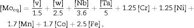
The results of wettability, showed that the PEO treatment promoted a hydrophobic surface (contact angle>90°) for all samples, and the SFE was quite close for three samples. The SFE is related directly with the process and reactions at the surface. If the SFE is high, the surface can interact more easily with other specimens, for instance in biological terms with cell adhesion processes [41], and the corrosion and wear properties could be stimulated. For the three samples modified by PEO, the SFE was quite close, being 35mN/m for CP-Ti, 34mN/m for TN-15 and 31mN/m for TNZ33. In another works, the SFE reported were higher, being 56mN/m for Ti64 substrate [42], in the range of 40–72mN/m for Ti64 and CP-Ti [43] and 50–60mN/m for c.p Ti, Ti–6Al–7Nb, Ti–45Nb and Ti–35Zr–10Nb [44]. It appears that surface morphology and chemical composition of the ceramic layer do not have a critical influence on SFE as stable hydrophobic surfaces. However, these surfaces have a 3D geometry formed by porosity which might be beneficial for the formation of bone tissue also be used to facilitate functionalization of the surface looking to reduce infection or to encourage growth of tissue. Besides, some recent studies have been demonstrated a hydrophobic surface reduce the proliferation of some bacteria, preventing biofilm formation [45].
Some studies have been reported that the SFE value is linked to the presence of different oxides. Lim et al. [46] reported that surfaces composed only for rutile are hydrophobic whereas when the surface is composed of a mixture of anatase and rutile phases, the surface becomes hydrophilic. On the other hand, surfaces formed only for anatase have been reported to be also hydrophilic [47]. The high SFE found for CP-Ti (35m/mN) which was formed by mixture of anatase and rutile is in agreement to the Lim et al. The ceramic surface formed on TN15 substrate have the mixture of anatase, rutile and Nb2O5, indicating that the Nb2O5 is a hydrophobic oxide and the amount of rutile is higher than the CP-Ti surface. However, in the ceramic surface on the TNZ33 substrate, was found a mixture of rutile and ZrO2. The TNZ33 ceramic surface presented a SFE of 31m/mN lowest than the others one. This result presents two hypotheses: the ZrO2 is a hydrophobic oxide such as rutile, as reported by Lim et al., or the ZrO2 present a hydrophilic profile and its amount is significantly small compared to rutile, consequently promoted a hydrophobic surface.
ConclusionsPlasma electrolyte oxidation (PEO) technique was used to create a porous ceramic layer formed by different oxides on Ti samples, depends on this chemical composition and microstructure. An electrolyte bioactive solution with the presence of Mg, Ca and P elements was used. The main findings in this work are highlighted below:
- •
The PEO coating promoted the formation of rutile (R) titanium oxide (TiO2) in all substrates, as well as CaCO3 (C) and Ca3PO4 (CP);
- •
The anatase (A) TiO2 was found on CP-Ti (alpha) and TN15 (α′+β) substrates;
- •
The biphasic TN15 alloy promoted the formation of amorphous halo, detected by the XRD profile, indicating that the temperature of PEO was not enough to crystallize the oxides;
- •
The crystalline oxides formation was dependent of the microstructure, phase and chemical composition of the substrate;
- •
The TiO2-based ceramic layer formed was thicker for TN15 substrate followed by TNZ33 and CP-Ti;
- •
The pore distribution (more homogeneously for TN-15) and roughness (higher for TN-15) presented a tendency based on microstructure and phase formation;
- •
All the bioactive elements (Mg, Ca and P) were found on the ceramic layer formed of the three samples, and high concentration of P on TNZ33 sample;
- •
Contact angle were higher than 100° characterizing three surface samples as hydrophobic ones and no significative difference was detected;
By these findings, the main conclusion and innovative points of this work is that the microstructure formed by α′+β phases promoted better ceramic layer characteristics. However, the TNZ33 formed just for β-grains leading to crystallization of TiO2 during the PEO coating, possible due to the presence of Zr, which is extremely reactive.
This study was financed partly by the Coordenação de Aperfeiçoamento de Pessoal de Nível Superior of Brazil (CAPES); Fundação de Amparo à Pesquisa do Estado de São Paulo (FAPESP), Finance Code 001, and Ph.D. grant #88887.371759/2019-00 (R.F.M.S.), and by FAPESP (São Paulo State Research Foundation) [“Projeto Temático” #2018/18293-8; pós-doc grant, #2021/03865-9], whom the authors thank.

