


With the commissioning of the Atlantic high speed railway line between Pontevedra and A Coruña, in the spring of 2015, the viaduct over the river Ulla has achieved the world record in the typology of high speed composite truss bridge, with three main spans of 225+240+225m. This exceeds the Nantenbach Bridge over Main River in Germany, which held the record since its conclusion in 1993 with a 208m span.
This article describes in detail the design and the main features of the viaduct, the new system of quality control of the execution implemented with great success. A description is also presented on the complex and outstanding construction processes used for the execution of the deck of the bridge and the foundation of the piers located on the river, with the exceptional temporary works that have been fabricated “ex profeso” for the execution.
Con la puesta en servicio del Eje Atlántico de Alta Velocidad entre Pontevedra y A Coruña, en la primavera de 2015, el viaducto sobre el río Ulla se ha convertido en el récord del mundo en la tipología de celosía mixta de alta velocidad con tres vanos de 225+240+225m que superan al del puente de Nantenbach sobre el río Main, en Alemania, que ostentaba el récord desde su conclusión en 1993 con 208m de luz.
Este artículo describe con detalle la concepción y las principales particularidades del viaducto, el novedoso sistema de control de calidad de la ejecución implementado con gran éxito, así como los complejos y singulares procesos constructivos empleados para la ejecución del tablero y de las cimentaciones de las pilas en el cauce, junto con los excepcionales medios auxiliares que ha sido necesario fabricar ex profeso para su ejecución.
The viaduct over River Ulla at the mouth of Arosa Estuary constitutes the most prominent structure on the Atlantic high speed railway line between Pontevedra and A Coruña in northwestern Spain. Its three centre spans are now the world's longest on a composite truss bridge for high-speed rail traffic [1].
Its site near the Arosa Estuary, in extraordinarily beautiful surroundings subject to strict environmental protection, induced the Directorate General for Railways to shortlist an ideas competition. The solution submitted by IDEAM was awarded the contract for the detailed design, which was geared to meeting the following objectives:
- •
to sustain the aesthetic proposed and ensure that the structure would blend into its surrounds;
- •
to minimise the number of piers in the riverbed while building the viaduct to the technical requirements of a high speed railway bridge at an affordable cost;
- •
to deploy construction processes with the lowest possible impact on the riverbed and banks;
- •
to maximise transparency and minimise the visual impact on the surrounding landscape.
The prominence of the works and their inevitable effect on the landscape called for a design that would blend suitably with or even enhance the surrounds. The solution, inspired by the beauty and environmental variety of the estuary, was based on a highly transparent truss design in which depth transitions between the riverbed piers were smoothed with fish belly-shaped curvatures. The resulting deck appears to ‘float’ over the estuary (Figs. 1 and 2), in a deliberate digression from the traditional angular variations in depth that would have rendered the support afforded by the centre piers overly conspicuous.


With its pearl grey concrete and light green steel truss, the viaduct blends discreetly and elegantly with the surrounds, where the predominantly green woodlands and grey river are sprinkled with bright reflections on the occasional sunny day and filtered through a cloak of mist and fog on so many others.
2Structural concept and descriptionThe conditioning factors described in the Introduction informed a solution consisting in a continuous truss bridge with a steel and concrete structure that would afford double composite action in the negative moment areas. The typical approach spans were to measure 120m and the three long main spans 225, 240 and 225m, the longest 20% longer than the former world record 208-m centre span on Nantenbach Bridge over the River Main [2] in Germany.
The design for the 1620m viaduct envisaged 12 spans (50+80+3×120+225+240+225+3×120+80m) (Fig. 1) and two joints fitted with track expansion devices at the abutments.
The five variable depth spans (Fig. 2) were designed to measure 17.90m over the bearings (17.50m steel) and 9.15m (8.75m steel) at mid-span, and the likewise composite truss on the 120-m approach spans were to have a constant total depth of 9.15m.
The four artfully designed goblet-shaped centre piers (P5 to P8) were to be stiffly secured to the composite truss deck, forming a composite portal frame sufficiently stiff in the three centre (225+240+225-m) spans (Fig. 2) to bear the strain induced by high speed and the concomitant live loads on alternating spans.
The design optimised the stiffness in the four main piers to constrain deck rotation as required, while controlling the bending moment transferred via frame action to the pier foundations to elude any need for over-dimensioning [3].
To that end, the main side piers (P5 and P8, Fig. 2), located on the outer ends of the 225-m spans, were designed with two unengaged walls restrained at the foundations and pierhead. This arrangement would control the moment restraint deriving from the hugely different lengths of the two adjacent spans (225 and 120m), as well as the bending moment stemming from temperature- and rheology-induced pierhead displacement. These effects would be perceptibly greater in P5 and P8 than in the two centre piers (P6 and P7) due to the substantially longer distance, on the order of 350m, to the zero displacement point on the deck.
The remaining approach piers were designed to have conventional hollow rectangular sections and variable length- and transverse dimensions. In the design, the spherical deck bearings on these piers were longitudinally detached, with transverse displacement constrained in one of them and free on the other.
The Warren truss envisaged in the design would consist in 15-m long modules in which the two lateral sets of nodes on the upper chord would be spaced 6m apart and the diagonal web members slanted at around 45° from the horizontal in the constant depth area; the sheet steel would form parallelograms 0.80m wide and 1.00m deep on the upper chords and diagonals and 0.80m wide and 1.20m deep in the bottom chord.
In the design, the upper chords were crowned with an additional closed profile welded to the upper flange to be embedded in the concrete slab. By welding the connectors to the sides of this member, the load transfer axis in the connection would be closer to the barycentre of the upper slab, thereby reducing eccentricity-induced parasitic bending moments on the connection (Fig. 3).

S355-J2+N and S355-K2+N (for sheets over 60mm) quality steel was specified for the truss in the approach spans, and S-460-M and S-460-ML (for sheets over 65mm) in the three variable depth, longer centre spans.
The top slab depth was to vary from 0.46 to 0.25m and the RC-35 cast-in-place concrete was to be poured on composite, full-width precast slabs.
In the design, the RC-50 bottom slab would be cast between and secured to the two bottom chords to establish double composite action in the areas subjected to negative moments. In all other areas, the bottom concrete slab would consist in merely formal, i.e., non-structural, concrete to facilitate inspection and maintenance (Fig. 4). Except as otherwise indicated below, the aforementioned design specifications were implemented in viaduct construction.
3Foundation construction
Further to the geological survey, the uppermost level of the ground under the alignment consists in loose colluvium on the banks and alluvium in the estuary, both resting on a granite substratum with a more or less altered surface.
The abutments and simple land-side approach piers P1 to P4 and P8 to P11 have shallow foundations (footings) built over the granite substratum where the mean allowable stress is 1.00MPa. Two of the three riverbed piers (P5 and P6) rest on 1.5-m diameter capped piles restrained in the sound granite, while the third (P7) has shallow foundations built directly on the rocky substratum.
3.1Provisional wharf to access riverbed foundationsA provisional wharf was built to provide access to the foundations for the three riverbed piers (Fig. 5) and carry the steel deck segments to the positions from which they could be hoisted into place. The nearly exclusive use of land-based resources for construction that this entailed hastened works progress while respecting the environmentally protected banks.

The deck over the wharf consisted in a series of statically determinate steel spans 6m long and 14m wide (Fig. 6) to accommodate two 4.5-m traffic lanes separated by a 1-m central reserve, plus two 2-m wide outer corridors divided in two, half for laying supply pipes for the construction areas and the other half for pedestrian traffic. This deck was supported by lintels resting on steel CHS piles 800mm in diameter and 12mm thick, driven with a pile hammer to the sound layer. Ref. [4] contains a detailed description of the typical cross-section and construction process for the wharf.
3.2Provisional sheet pile enclosures in riverbed foundations
Provisional enclosures (Fig. 5) were built around the sites for the three riverbed piers for dry construction of the foundations. These enclosures were also used as working platforms to erect the piers and hoist the steel deck segments into position.
These structures, with 62-, 68- and 65-m outer diameters at piers P5, P6 and P7, respectively, consisted in sheet piles forming two concentric rings spaced at 10m and designed to bear bending moments. Both rings were hooped with circular braces positioned at several levels, the steel hoops on the outer ring to bear tensile and the reinforced concrete hoops on the inner ring to bear compressive stress [4].
The inner sheet piles in piers 6 and 7 were driven to rock depth. The excavation depths were 8m in P5, 10.5m in P6 and 13m in P7 (Fig. 7). At peak high tide the estuary rises to 2.54m above sea level, very near the elevation of the enclosure platforms (+3.0m). Such deep excavations, on the order of 15m, and the presence of water around the exteriors, called for enclosures with substantial retaining power.

The outer rings were braced with perimetric S-355 steel hoops. Piers 5 and 6 were hooped with one such member each, while two were required in pier 7 (Fig. 7).
The compression braces circling the inner sheet pile walls were RC-40 hoops with a 1.0×1.0-m rectangular cross-section. Three braces were needed in piers 5 and 6 (Fig. 8) and four in P7.

In addition, a double ring of columns was jet-grouted around the inner sheet pile wall in all three enclosures to seal the interface between the rock and the sheet piles to prevent leakage. These columns also played a structural role in pier 6, where the bearing capacity inherent in their circular shape provided lateral support for the toes of the sheet piles.
As greater strength was needed to restrain the toes on the inner sheet piles in pier 7, which became detached during excavation, a reinforced micropile was built at the foot of each sheet pile to resist the resulting shear stress (Fig. 7).
3.3Enclosures and riverbed foundationsThe sheet piles for the outer rings in the enclosures were vibration driven from the wharf and subsequently braced with steel hoops.
The backfill for the inner enclosure ring was dumped from lorries standing on the wharf into the stipulated space, previously lined with geotextiles to minimise the outflow of fines into the estuary.
The sheet piles for the inner enclosures were then driven from the surface of the fill, after which the feet of the sheet piles were superjet-grouted. Lastly, the P7 enclosure was micropiled from the platform.
Pier 5 foundations consisted in 42 capped piles 1.5m in diameter, while in pier 6, 56 piles were driven 1.5m into the grade I-weathered granite substratum. In both cases the operations were performed from the top of the enclosure fill at an elevation of +3.0m. The piles were sheathed in re-usable casing until they struck rock; the use of sludge was avoided to prevent possible leakage to the estuary. The casing was driven until contact was made with the more or less altered rocky substratum or, where it appeared, with very dense, compact granite gravel. After all the piles were driven, the enclosures were excavated (Fig. 8), the hoops were built at the respective levels and the pile heads were cut down (Fig. 9) to accommodate the rebar (Fig. 10) and cast the concrete for the pile caps.

.")
The pier 5 and 6 pile caps measure 30×24×4.5m (Fig. 10) and 34.5×30.5×5m, respectively; the bottom pile cap elevation is −5.0m in the former and −7.5m in the latter.
Given these dimensions which translated into a volume in the larger of the two of 5260m3, concrete casting was hardly an insignificant operation. Concrete was poured continuously, in one case for over 50h, in the three riverbed pier foundations. Several types of concrete were used, depending on the layer of the pile cap. SCC-35 self-consolidating concrete was applied in the bottom 0.7m to ensure adequate placement around the dense bottom reinforcement; conventional vibrated RC-35 was used in the middle area; and FRC-35 fibre-reinforced was poured in the uppermost metre to prevent surface cracking. Furthermore, in the inner area that interfaces with the concrete pier, the material used was of the same quality in both, RC-70. The RC-35 piles were designed for service loads of 8MPa.
The shallow foundations under pier 7 consist in a 27×24×5.25-m footing, set at a depth of 8.6-m. The lean concrete (RC-15) across which the footing rests on the grade III- (or lower) weathered granite substratum bears a maximum co-barycentric stress of 0.76MPa and a maximum peak stress of 1.00MPa (Fig. 11).

Upon completion of the riverbed foundations, the enclosures were filled and the inner hoops demolished, in the reverse order of construction during the filling operation. The inner sheet piles were subsequently removed, leaving the islands ready for deck segment transport and hoisting.
The tops of the P5, P6, and P7 pile caps are located on the order of 1m below the natural riverbed. Consequently, with the removal of the inner fill, the outer enclosures and the wharf after the deck was erected, the estuary was restored to its original state.
4Deck manufactureIn light of the singularity and complexity of the steel structure and the huge volume (nearly 20000t) of structural steel required for the deck, the contractor proposed and the site management agreed to divide manufacture between two groups of steelworks. Initially, half of the viaduct was to be manufactured at the Ascamón-Joama plants in the Spanish region of Asturias and the other half at Martifer, a plant in Portugal. The complexity of the works and the construction deadlines subsequently necessitated the enlistment of two additional manufacturers in the Spanish region of Galicia: Emesa and Dizmar (Fig. 12).

To simplify handling, manufacture and shipping, the trusses forming the deck were conceived from the design phase to comprise the following standard components (Fig. 13): upper nodes, upper chords, diagonal web members, bottom nodes, bottom chords, tie girders and cross-braces.

Once all the separate components of each segment were made, they were welded into larger sub-assemblies: node+chord or node+chord+node. These sub-assemblies and the remaining standard components (diagonal web members, tie girders and braces) were shipped to the site yards for final assembly.
To that end, three large-scale segment assembly bays (Fig. 14) were built on site, all with capacity to assemble segments up to 17.5m high. In addition, wide spaces were cleared near abutment 1 (A1) and underneath the viaduct between pier P9 and abutment 2 (A2) for use as on-site storage and assembly yards.
4.1Steel structure quality control
The detailed specifications for the project laid down the general criteria on which on-site workmanship quality control for the steel structure was based [5]. The core principle consisted in vesting the contractor with responsibility for accrediting steel structure conformity to the existing legislation on steel structures as part of its quality control programme. The aforementioned specifications stipulated that the contractor could be commissioned to directly conduct and certify all the controls set out therein or assume responsibility for the control conducted by the steelworks, subject to verifying at least 20% of the plant trials. Consequently, the unit price included the cost of all control tasks incumbent upon the contractor.
The detailed specifications required the contractor to ensure compliance by each and every manufacturer with absolutely all the stipulations on control and hire an independent control body to be permanently on site at the plants and the worksite. This body was responsible for certifying conformity of steel structure workmanship on behalf of the respective manufacturer and reporting to the site management accordingly.
It also supervised and validated at-plant and on-site steel structure manufacture throughout, including material orders and acceptance, approval of welds and weld procedure qualifications and review of the workmanship controls and non-destructive testing (NDT) conduced at the plant.
In addition to continuous plant and quality control system supervision and auditing, the contractor's quality control bodies (Alfainstant and subsequently AMT) verified at least 20% of the trials conducted by the steelworks. Such verification was not confined to merely repeating non-destructive tests (penetrant testing, magnetic particles inspection, ultrasonic testing and radiographic testing), but during the assembly stage also included inspection of sheet cutting and edging (groove preparation), dimensional controls, pre-weld visual controls and geometric controls and trial assembly, to name a few.
In addition to the contractor's control system, the site management was assisted by a team of engineers (TYPSA), on which the designer firm (IDEAM) sat as expert steel structure adviser, as well as by a further independent quality control body (Applus). The latter audited the contractor's entire workmanship control system and had further verification trials (around 20%) conducted by a QC laboratory which also performed random NDT verifications.
The contractor's entire control system was set out in three inspection point programmes: steelworks manufacture, worksite plant assembly and on-site assembly, which established the percentage of self-control trials conducted by the manufacturer and the verification trials conducted by the contractor's control body.
The contractor's quality assurance plan described the control systems and mechanisms and contained an organisational chart showing the tasks and responsibilities of all the agents involved in manufacturing and quality control. It also established the mechanisms for reporting incidents and non-conformities.
A manufacturing or assembly incident was defined as a flaw or non-conformity detected at the steelworks during any of the manufacturing stages. All incidents, regardless of their significance, were reported to the contractor's and the site management's control bodies. Minor incidents were reported by the manufacturer, documented and solved, with no need to suspend production. Incidents of greater significance were reported to the control bodies and the solution agreed upon by the contractor's control body and the manufacturer, based on the repair procedure proposed by the latter.
Workmanship flaws or defects detected by the contractor's control body but not by the manufacturer's quality control system constituted non-conformities.
Non-conformities were filed, for instance, when the steelworks plant detected recurrent incidents in a given process, such as dimensional flaws or defects in typical welds identified by ultrasonic testing, denoting a systematic flaw of much greater significance than an occasional individual flaw or defect calling for process or control procedure restructuring rather than mere sporadic repair.
Non-conformities identified by the contractor necessitated suspension, documentation of the non-conformity, analysis of the cause and proposal not only of an ad hoc solution, but corrective measures to prevent systematic or recurrent defects. Implementation of repairs and resumption of production was contingent upon the site management's validation of the proposal.
The inspection point programmes stipulated specific control procedures and acceptance criteria. Measures were taken prior to works commencement to ensure that all the actors involved in workmanship control were fully aware of the criteria to be applied and the schedules that would be used to validate each specific trial. At the River Ulla Viaduct, control was based primarily on European standards (EN series) and their translation into Spanish (UNE-EN series). Other legislations (essentially American, AWS series and similar) were resorted to only in the absence of relevant EN standards.
After welding, plant sub-assemblies were only authorised for shipping or worksite yard steel segments for on-site assembly where conformity with all the workmanship controls and NDTs laid down in the respective inspection point programme was documented and fully certified.
4.2Shop drawings for steel structuresThe complexity of the works, the geographic scatter of the steelworks and the many control agents involved led the contractor to hire a Steel Structure Construction Coordinator, who served as a liaison between the site management and its technical assistance team for steel structure-related matters. One of the foremost responsibilities of the position was to coordinate and unify all technical proposals for adapting, modifying or adjusting a given detail among all the plants.
Another essential factor on which control was based was the system for approving and validating shop drawings for the steel structure.
The steelworks developed detailed shop drawings and cutting sheets for each steel plate from design drawings. Responsibility for accrediting shop drawing and cutting sheets conformity was vested in the contractor, who in turn outsourced the task to a specialised consultant. After the shop drawings were approved, they were forwarded to the site management's technical assistance team for in-plant supervision and authorisation or observations for corrections.
The complexity of the steel structure called for considerable prior study and development of a series of recurrent details by all the parties concerned (steelworks plants, contractor and technical support team, together with the design engineer who assisted the site management) to ensure that the shop drawings contained the solutions for all connections, welds, transitions and specific details to prevent problems from arising during construction. The level of definition of the shop drawings for the steel structure is described in Ref. [6].
Many possible worksite problems were avoided by not accepting under any circumstances drawings for dimensionless or tabulated typical details that failed to represent plate thickness, geometry, angle of incidence, root openings, root faces or groove preparations at all the specific welded connections.
The 131 design drawings defining steel structure details spawned over 6000 shop drawings and nearly 20000 cutting sheets, with precise definitions for each steel plate, connection and weld on the bridge. Such meticulous engineering was imperative to guarantee the satisfactory visualisation of all the details, given the need to comply with very strict fatigue resistance standards in light of the mission and nature of this composite high speed viaduct.
4.3Assembly sequence drawingsIn addition to the shop drawings and cutting sheets, assembly drawings were prepared for each typical component (upper nodes and chords, diagonal web members, bottom nodes and chords, upper and bottom tie beams and cross-braces), defining:
- •
the assembly bedplates;
- •
weld order and sequence, including the pre-assembly tack welds;
- •
weld procedures, methods and positions and thermal pre-treatment;
- •
the ancillary resources needed to provisionally brace the steel plates in each component;
- •
tools for turning and all other ancillaries required for handling components;
- •
all the intermediate stages involved in assembling standard components, sub-assemblies or segments.
As the fatigue resistance of a permanent bridge component may be weakened by welded ancillaries, re-usable hoisting and turning tools (Fig. 15) were designed for handling nodes, chords, diagonals and so on with no need for such devices. This proved to be an efficient and effective approach, given the modularity of the structure and the many components with identical outer geometries.

Where lugs were needed to assemble large-scale segments on site, they were consistently defined on shop drawings with suitable fatigue details, dismounted further to specific removal and repair procedures and subject to intense subsequent control.
4.4Splicing of standard components and fatigue resistance designThe connections between chords and nodes were designed to elude the need for four welds on the same cross-section, staggering flange and web connections with a geometry that favoured welding bearing elements prior to loading them with the elements to be borne. As Fig. 13 shows, as a rule the nodes were formed with the end of the bottom flange cantilevered and the end of the upper flange set back. That geometry was reversed in the chords to simplify adjustment and assembly and to avoid establishing four welds on the same section (Fig. 16).

With this geometry, a coupon could be cut into the top flange at the end of the chord to more readily perform three full penetration butt welds with flush-finish dressing inside the cross-section (formed by the webs and the bottom flange). As a result, a fatigue detail category 71 [7] weld with a backing strip was converted into at least a fatigue detail category 80 butt weld dressed to flush [7].
Wherever possible, steel structures should be designed without single-sided welds, which indispensably call for the use of steel backing strip. Rather, butt welds should be made from both sides or from one side with provisional ceramic backing strips and subsequent dressing to a flush finish. Butt welds with steel backing strip, in addition to delivering a lower detail category, may generate a series of problems described in greater depth in [6].
As a rule, in a more conventional bridge with composite girders or box girders, such as the Arroyo las Piedras [8] or Archidona [9] composite high speed railway viaducts, the main butt welds in webs and flanges are nearly always made from both sides, obviating the need for single-sided welds with steel backing strip. In trusses, on the contrary, the latter solution must often be adopted, for the connections between nodes and chords and nodes and diagonal web members are often accessible from the outer side only, necessarily requiring the use of steel backing strip.
On the River Ulla Viaduct, although efforts were made to minimise their use, many connections, such as between diagonal web members and nodes (Fig. 13) or the welds joining flanges in node-chord connections, called for steel backing strips. Ref. [6] contains a detailed description of the precautions that must be taken in the performance and control of single-sided butt welds with backing strips to ensure that the connection actually welded is a fatigue detail category 71 according to UNE-EN 1993-1-9 [7].
4.5Fatigue in connections and transitionsIn a truss structure with nodes at 15-m intervals, the connection details are recurrent, with the exception of minor variations in the dimensions (thickness) of the plates and the welds. Hence the importance of a suitable approach with a design geared to welds with a satisfactory fatigue detail category.
A few examples of the main repetitive details, in which each node was fully defined on the shop drawings from the outset, are summarised below.
- •
The drawing on the left in Fig. 17 details the transition for the fillet weld between the flange and web of a diagonal or chord at its interception with a truss node, where the diagonal or chord flange is joined to the web in the truss node with a partial penetration weld, generating a cup hole in both the plan and elevation views, which was remedied with transitions and moderate grinding along the edges of the weld. To ensure suitable fatigue performance, 12 cup holes had to be sealed in each node. To elude the existence of such a large number of sealing strips, which could detract from durability, the solution adopted was a moderate transition with slopes of 1/5 between the fillet weld outside, and the partial penetration weld inside, the centre of the node, as shown in the photograph on the right in Fig. 17.
- •
The detail for web insertion nodes called for transitioning from two partial penetration but welds with groove preparations on the notched flange only to two partial penetration welds with groove preparations on both the notched flange and the edge of the web. That in turn required moderate (1/5) transitioning to accommodate the change in the groove, as defined in detail in the shop drawings for each case (Fig. 18).
- •
Further to detail 3 in Table 8.4 in Ref. [7], to attain a fatigue detail category 80 the edge finish on the webs in web insertion nodes must be tapered and rounded with a radius of over 150mm and have a ground tangent weld (Fig. 19).
- •
Fig. 20 depicts the detail for the end of the weld connecting a web to an upper flange on the bottom node or a bottom flange on the upper node, where the partial penetration weld between notched flange and web was crowned with a tapered, 1/5 slope transition at a cup hole located at the end of the web. The cup hole was subsequently sealed with a plate to ensure node weather-tightness.
- •
To brace the upper truss chords along the entire deck and the bottom chords in the variable depth area, a bracing plane had to be established with X-braces made of CHS profiles, welded to gussets in turn welded to the node flanges. Application of this solution, which is more or less conventional in steel and composite decks, to a highly recurrent detail on this viaduct was contingent upon the following precautions to ensure its suitability.
- -
Further to detail 4 in Table 8.4 in Ref. [7], to comply with a fatigue detail category 90, gusset edges must be tapered and rounded with a radius of over 150mm and the edge of the weld must be ground (Fig. 21).
![Detail 4 from Table 8.4 in Ref. [7] and tangent weld in a gusset-flange node.](https://static.elsevier.es/multimedia/04395689/0000006600000277/v2_201703310305/S0439568916000024/v2_201703310305/en/main.assets/thumbnail/gr21.jpeg?xkr=ue/ImdikoIMrsJoerZ+w96p5LBcBpyJTqfwgorxm+Ow= "Detail 4 from Table 8.4 in Ref. [7] and tangent weld in a gusset-flange node.") Figure 21.
Figure 21.Detail 4 from Table 8.4 in Ref. [7] and tangent weld in a gusset-flange node.
- -
Gussets must as a rule be thinner than the main plates on a bridge, in this case on the nodes. Consequently, resorting to the more conventional solution of transitioning from the thicker steel was not judged to be the best approach, for it would have weakened the strength of the main longitudinal section. Here, butt welding the gusset to the flange and transferring the stress on the gusset to the flange more smoothly with an additional fillet weld was deemed to be a more suitable solution (Fig. 21).
- -
 and detail with transition and no cup holes (right).")


![Detail 4 from Table 8.4 in Ref. [7] and tangent weld in a gusset-flange node.](https://static.elsevier.es/multimedia/04395689/0000006600000277/v2_201703310305/S0439568916000024/v2_201703310305/en/main.assets/gr21.jpeg?xkr=ue/ImdikoIMrsJoerZ+w997EogCnBdOOD93cPFbanNcmaQhbHYBdp0SiDFRxASFlCCXC4M6VtYS12saK2YND8uR1GG+desXWQPTb3sPHnasRBQEkkshquBCwY2wc6in3v6SlNdCXaJ9bKUwEhMep1940aquvuje79jkJcsghsFK00Z2VWUZnTk9zQG91aLhXAiNfeAVDasMfc2XUA4q79bD+6scqt08AheF6h8KyHYiQ37nxz6CVccdoqKJns7haRgO6oqiUOeMuyWpRI0WNFvV6QUslIBBer51Of6NOLYs= "Detail 4 from Table 8.4 in Ref. [7] and tangent weld in a gusset-flange node.")
The design for the steel structure in the four constant depth (50+80+120+120m) approach spans on the left bank (Fig. 1), positioned between A1 and P4, stipulated that the segments should be hoisted onto provisional shoring where they were to be welded to ultimately form a continuous girder.
After the works were awarded, the River Ulla joint venture studied an alternative procedure. The initial proposal was adapted to use launching technology on spans 3 and 4 (between piers P2 and P4) in light of the scant accessibility of these areas, particularly for segments and cranes, in addition to the presence of two roads underneath the alignment between P2 and P3 and a railway track near P4.
This construction procedure, in keeping with the original design, adopted the general principle of building a continuous girder as the bearing structure and an overhead yard between A1 and P2 for segment assembly, while eluding hoisting operations between P2 and P4.
The launching gantry had to be installed on piers P1 and P2 and provisional overhead shoring was required to avoid interference with a tunnel close to A1 in the preceding section of railway, awarded to another contractor.
Construction on the four spans was divided into three stages, as shown in Fig. 22.

In the first stage, the segments needed to build 120-m span 4 were hoisted with cranes to the launching gantry and positioned on shoring between A1 and P2 and on piers P1 and P2. Upon completion, this 120-m section was launched from P2 to P3 from an ancillary structure anchored to P2. Given the -1.8% grade in this stretch, the section was back-stayed to A1 throughout the operation, during which jacks positioned on P2 pulled on the gradually lengthened back stay cables.
Shoring sited at two intermediate positions between P2 and P3 served as support for the section launched, shortening the length of the cantilever (Fig. 23). Several of the shoring structures between A1 and P2 were used for provisional assembly operations only, i.e., not for launching operations per se.

In the second stage, the span 3 segments were hoisted to the launching gantry and connected to the section launched previously by continuous welding. The full 240-m section comprising spans 3 and 4 was then launched from P3 to P4 (120m).
The photograph on the left in Fig. 24 depicts the beginning of the second stage, as the section was launched off P3, while the middle photo shows the section in place between P3 and P4 at the end of the operation. An intermediate shoring structure positioned between P3 and P4 reduced the front end span to 60m. The picture on the right in Fig. 24 shows a crane hoisting the stage 3 segments (Fig. 22) between P2 and A1.

Ref. [10] contains a detailed description of the launching process; the criteria followed to position jacks on some of the provisional shoring to directly or indirectly control the reaction on each bearing throughout the process; the intermediate stages between two launches; the ancillaries needed for the operation, including front jacks and collapsible nose beams, rear jacks, lugs for hooking onto the launching units and back stays, among others; and the controls conducted during the two operations.
5.2Hoisting of full sections to build right bank approachesIn the design, the three constant depth approach spans (120+120+80m) on the right bank of the River Ulla running between P9 and abutment A2 were to be erected by hoisting segments onto provisional shoring where they would be welded to ultimately form a continuous girder.
In the absence of any hindrance at ground level between P9 and A2, the River Ulla joint venture proposed to adapt the construction procedure and sequence, building the three spans on more readily accessible low shoring platforms directly underneath the final deck location, and subsequent hoisting into place one by one. The construction and hoisting sequences are shown in Fig. 25.

In the first stage, the sections were built underneath the future deck on shoring barely raised off the ground (Fig. 26).

To hoist the 465-t structure for span 12 (Fig. 27), it was provisionally restrained by anchoring the top of segment zero to adjacent abutment A2 and attaching boxes filled with sand to the bottom as an arrester against the abutment [11]. Due to its delta shape and hinge at its provisional bearing, the zero segment on the P11 end was temporarily restrained (from the time it was positioned until immediately prior to hoisting) to prevent overturn. The hoisting cables were then hooked to the end of span 12 and secured with back stays to the heavier preceding section to prevent overturn during hoisting, during which the provisional torque restraint was released.

The hoisting and staying reactions as well as segment zero geometry were controlled during hoisting.
After the first section was hoisted, its zero segments on both ends were provisionally secured and thus braced it was welded into position, after the connections were duly fitted. Reels with extra cable were designed for each connection and positioned at the ends of the chord and diagonal for quicker and easier alignment of the components for overhead connection.
With the first section in place and segment zero on the second in position at P10, span 11 was hoisted between P10 and P11 (left photograph in Fig. 28). As this 900-t, 120-m long (centres) section had to be offset on the span 10 side with a section of similar characteristics and weight, to secure segment zero on P10, a counterweight had to be used to enhance safety and prevent possible overturn of the pierhead segment during hoisting.
 and 10 (right).")
In the third and last hoisting operation, the 965-t section running between P9 and P10 was raised from both ends and joined by continuous welding to the two adjacent spans (photograph on the right in Fig. 28).
See Ref. [11] for a detailed description of the hoisting process for these three spans and the ancillaries needed.
5.3Balanced cantilevering construction of variable depth spansDue to the environmental protection afforded the estuary, the five variable depth centre spans, measuring a total of 930m, were erected with balanced cantilevering techniques from the four centre piers, as envisaged in the design (Fig. 29).

The large size and heavy weight of the steel ‘W’-shaped zero segments in each pierhead added to construction complexity. Each side of the 375-t segment measured 35m long and 17.5m high. The standard components shipped from the plant were assembled with each side of the segment face down on the platforms resting on the sheet piles at the foot of each pier (left photograph, Fig. 30) used to build the foundations. Once all the components were welded, the two sides were uprighted simultaneously with a large (25-m high) provisional ancillary structure positioned on the pierhead (right photograph in Fig. 30). This complex operation involved simultaneously jacking the top members of the zero segment upward and sliding the bottom members, propelled by jacks and connected to skid shoes, toward the pier on tracks (Fig. 30).

The two uprighted sides of the segment were balance-hoisted (left photograph in Fig. 31) to the pierhead elevation. To position these two huge elements in their permanent location they had to be skidded inward, secured to a pin connection at a lower level and subsequently rotated from the head of each side to slope each half-segment on a grade of 1/17.5. Once in their permanent position, the two sides were inter-braced at the upper tie girders and their bottom chocks were concreted (right photograph in Fig. 31).

The concrete pierheads were subsequently cast, after which the piers and zero segment were ready for balanced cantilevering to commence.
Beginning at the zero segment, the steel structure to be cantilevered was divided into full width, 15-m long segments, with a 7.5-m stagger between the ends of the upper and bottom chords to facilitate overhead assembly. The following segments were cantilevered off piers P5-P8 (Fig. 32).
- -
Six segments were built in span 5 (PK−) and six in span 6 (PK+) from pier P5.
- -
Six segments were built in span 6 (PK−) and six in span 7 (PK+) from pier P6.
- -
Seven segments were built in span 7 (PK−) and six in span 8 (PK+) from pier P7.
- -
Six segments were built in span 8 (PK−) and six in span 9 (PK+) from pier P8.

The variable depth segments were assembled in two of the three assembly bays sited alongside the river banks (middle and right-hand photographs in Fig. 14). The segments measured nearly 17.50m high (the biggest ones) by 7.10m across at the top and nearly 10m at the bottom and 22.5m long from the nose of the upper chord to the rear of the bottom chord. They weighed a maximum of 300t each.
In light of their enormous size, for readier construction and shipping, the variable depth segments were divided into the following standard components: rear-cantilevered upper chord, front-end upper node, front-end diagonal and cantilevered rear diagonal, bottom node and cantilevered bottom chord, tie girders and cross-braces for upper and bottom nodes and chords (Fig. 33).

The segments were assembled on a production line two-by-two and trial assembled (Fig. 33) to ensure perfect alignment of the six ends after hoisting. Where physical trial assembly was not performed, the segments were joined virtually with computer software to ensure the same degree of precision and accuracy.
The elements on the ‘open’ segments (with staggered upper and bottom nodes [12]), i.e., the cantilevered rear of the upper chord, the cantilevered diagonal springing from the bottom node and the cantilevered bottom chord, staggered 7.5m beyond the upper chord (Fig. 33), had to be provisionally secured with specially designed braces. These devices controlled strain during transport and hoisting and adjusted the cantilevered ends of the diagonal and rear of the bottom chord for alignment with the preceding segment.
The variable-depth segments were transported on site on two separate (one for each side of the segment) self-propelled, multi-wheeled platforms (Fig. 34).

Span 9 was directly accessible by land and all the span 5, 6 and 8 segments could be hoisted from the wharves (Fig. 29). The section in the centre span between P6 and P7 was the sole balance-cantilevered member that was inaccessible from land.
One of the possibilities studied during the design and early into the works stage was to carry the two arms of the span 7 section in barges. That operation had to be ruled out, however, due to the difficulties involved. Ultimately, the segments for the centre span were hoisted into place over the estuary with mobile derrick cranes, as described in the following section.
With this solution, the variable-depth span sections were built with no contact with the ground below and hence without affecting the main riverbed, the marshes or the plant life on the bank, further to the project specifications.
5.3.2Derrick cranes for segmentsThis part of the deck was built with balanced cantilevering techniques first from P5 and P8 and subsequently from centre piers P6 and P7. This called for designing and manufacturing four derrick cranes, two stationary and two mobile, on which to position a hydraulic jack-based hoisting system.
The ‘stationary’ derrick cranes were so called because as they hoisted the segment from a position anchored to the deck (Fig. 35), they carried no load other than their own self-weight when travelling.

The mobile derrick cranes (Fig. 36), in turn, could collect a segment at the base of the pier, hoist it partially, carry it parallel to the direction of the bridge while suspended (underneath the existing cantilever) to its location at the end of the section under construction and then hoist it into its permanent position for welding to the preceding segment. As these mobile cranes were needed in the centre span between P6 and P7, two stationary and two mobile derrick cranes were designed and manufactured.

Since piers P5 and P8 were accessible from the ground or the provisional wharves, there the mobile derrick cranes operated like their stationary counterparts, hoisting the segments vertically while anchored to the deck, with no need to move suspended segments in any other direction than upward.
Hydraulic jacks propelled the derrick cranes over the truss on skid shoes over tracks resting on lubricated neoprene-Teflon bearing pads positioned on the closed profile crowning the upper chords.
The stationary derrick cranes were fitted with hoisting jacks that were aligned vertically with the hoisting lugs on the segments (Fig. 35) very near their centre of gravity. Once hoisted to the desired elevation, the segments were aligned with a transverse hoisting beam fitted with a slanted jack (Fig. 35) hooked to the alignment lugs, which were located at in the front end. When the alignment jack was released, the segment rotated, bringing the bottom chord into position, whereas when the jack piston was closed, the segment rotated in the opposite direction, moving the bottom chord away from its position [12].
The main difference between the mobile and stationary derrick cranes was that in the former the hoisting jacks and cables could not be aligned vertically with the hooking lugs positioned on the top of the segment when carrying suspended segments in a horizontal direction. Rather, the cables had to be realigned outward with a cross-beam located on the derrick crane, and a transverse hoisting beam had to be placed between the segment and the hoisting cables (Fig. 36). Once the segment was at its specified elevation, alignment cables were secured to the lugs located on one end of the element for minor re-positioning prior to welding [12].
5.3.3Overhead segment alignment and weldingWhen the segments were nearly in position, the accuracy of their alignment was verified topographically prior to welding to the preceding segment. Positioning involved the use of hoisting jacks, the transverse hoisting beam (in stationary derrick cranes) or stiffening cable tensor jacks (in mobile derrick cranes). As necessary, manual tensioners or jacks were used.
Overhead adjustment and welding were performed on specifically designed welding platforms protected from the wind and rain. Each derrick crane was fitted with four welding platforms: two at the front for adjusting and welding the upper chords, diagonal web members and braces (Fig. 37); and two at the rear, with longitudinal and vertical mobility to adjust and weld the bottom chords and braces at different elevations, depending on deck depth.

The front welding platforms were fitted with removable inner components that had to be in position to access the inner side of the chords and removed for the crane to move to the next position. The provisional stiffening was removed from the rear welding platforms when the crane was in motion.
Broadly speaking, the sequence to position a hoisted segment was as follows: assembly of the inner components on the front platforms, alignment and welding of the upper chord and upper cross-bracing, alignment and welding of the bottom chord and diagonal, change in rear welding platform position, coupling and welding of the bottom cross-brace, welding of the crowning profile on the upper chord, partial removal of the front welding platforms, and lastly, unhooking of the hoisted segment and travelling forward to the next hoisting position.
The photographs below show balanced cantilever progress from P5 (Fig. 38) and several stages of progress from other piers (Fig. 39).
5.3.4Joining balanced cantilevers.")
 and P8 (left) and subsequently from P6 and P7.")
With the exception of span 9, each pair of variable depth sections was joined by a segment with a special geometry. This segment was divided in two: an upper chord that was welded to the end nodes in the two adjacent cantilevers, and a lower element, consisting in two bottom chords, the mid-bottom node and two cantilevered diagonals springing from the bottom node.
The construction process was as follows in all cases.
- •
The bottom of the segment was hoisted and aligned with one of the two ends. The bottom chord and diagonal on the other end were fitted with cable on a reel for more accurate longitudinal alignment.
- •
The segment was provisionally secured with ancillary elements on the end opposite the chord and diagonal and the length of the cable was subsequently adjusted as needed to align and weld the joining segment.
- •
During the night, the ends of the two upper nodes were simultaneously secured with provisional tools to subsequently position the upper chord of the closing segment with the aid of adjustment cables on reels on both ends.
- •
Once all the components were welded and tested, the securing ancillaries were removed and the derrick cranes were released, closing the balanced pair.
The sequence followed to join the spans was as follows.
- •
On the P4 end of span 5, the segment was hoisted with the stationary derrick crane from the PK− end of the cantilever (Fig. 40).
- •
In span 9, a double segment was hoisted from the ground with cranes, one end was rested on P9 and the other welded to the PK+ side of the cantilever (Fig. 41). Span 10 was hoisted fully assembled from the end of the segment located on the pier (photograph on the right in Fig. 28).
- •
In span 6 the segment was hoisted with the stationary derrick crane from the PK− end of the P6 cantilever (Fig. 42).
- •
In span 8 the segment was hoisted with the stationary derrick crane from the PK+ end of the P7 cantilever (Fig. 43).
- •
The closing segment for the 240-m centre span (span 7) was hoisted with the mobile derrick crane from the PK+ end of the P6 cantilever (Fig. 44).


Once spans 5 and 9 were completed and the deck structure was continuous from A1 to P5 and A2 to P8, the bearings on piers P4 and P9 were lowered by 25cm in simultaneous and strictly controlled operations. The aim was to reduce the portal effect-induced bending moments on piers P5 and P8 resulting from the huge difference in the span lengths (225 and 120m) on either side of these two main piers. Lowering these bearings reduce the decompensated bending moments from the permanent loads on piers P5 and P8.
Lagging somewhat behind steel structure assembly, concrete was cast on the lower deck slab across the entire bridge. Composite structural concrete was cast in negative moment areas, while in positive moment areas unconnected to the truss, concrete was laid merely to ensure access to deck interiors for inspection purposes. The travelling formwork used to cast the bottom slab concrete in both the constant and variable depth areas of the viaduct (Fig. 45) hung from an upper ancillary structure attached to the crowning profile on the upper chords.

The upper slab concrete was cast on full-width precast slabs positioned with a tower crane mounted on the steel deck itself. This operation lagged behind both the steel structure assembly and bottom slab casting (Fig. 46).

Pursuant to standard practice in composite bridges with reinforced slabs, the upper slab was cast to a sequence that avoided self-weight-induced cracking in hooging areas (Fig. 46). Continuous watering and geotextile protection were deployed to prevent drying shrinkage-induced cracking in the slab.
6ConclusionsWith the commissioning of the high speed Atlantic railway between Pontevedra and A Coruña in spring 2015, the viaduct over the River Ulla (Figs. 47 and 48) set a new world record for span length in composite high speed truss typology bridges. Its three 225+240+225-m spans are longer than the 208-m span on the Nantenbach Bridge, which had held the record since its completion in 1993.


As noted in the foregoing, a number of circumstances make the River Ulla viaduct a unique structure, including:
- •
the use of three very complex construction processes: hoisting in place of whole spans, incremental launching and balanced cantilevering in the main spans;
- •
the use of unique ancillary resources manufactured explicitly to build the viaduct;
- •
the use of large-scale (up to 68m in diameter) sheet pile enclosures to dry-build the riverbed foundations;
- •
the face-down assembly of the zero segments for the centre riverbed piers (measuring 35m long by 17.5m high and weighing 2×375t), followed by complex and unprecedented uprighting and hoisting operations;
- •
the use of high thermo-mechanical performance steel uncommon in Spanish bridges (S-460-M and S-460-ML);
- •
the construction of three large on-site segment assembly bays with an indoor clearance of 20m;
- •
the on-site transport and hoisting of 300-t segments up to 17.5m tall with self-propelled multi-wheeled platforms;
- •
the use of high-strength (RC-70) and self-consolidating concrete on the centre piers;
- •
the >70-h uninterrupted casting of over 5000m3 of concrete in foundations, with thermocouple-controlled setting temperatures;
- •
the deployment of a standard-setting steel structure quality control system unprecedented in Spain for controlling steel and composite bridges and viaducts.
These unique features earned the River Ulla viaduct the 2015 edition of the Construmat award for the best civil works, 2015 edition of the San Telmo award, price awarded by the Galicia Demarcation of the College of Civil Engineers, and the accesit of the VII Aqueduct of Segovia 2015 prize awarded by the College of Civil Engineers and Fundación Caminos.
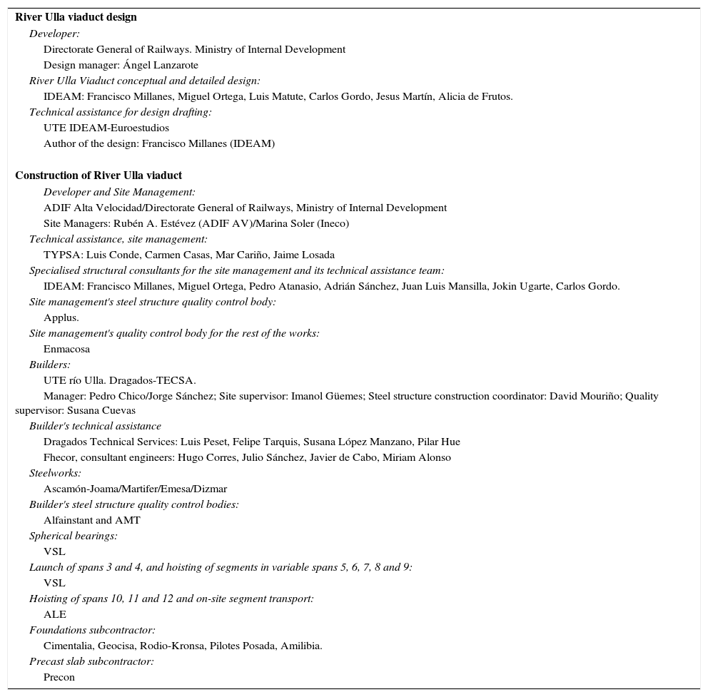
| River Ulla viaduct design |
| Developer: |
| Directorate General of Railways. Ministry of Internal Development |
| Design manager: Ángel Lanzarote |
| River Ulla Viaduct conceptual and detailed design: |
| IDEAM: Francisco Millanes, Miguel Ortega, Luis Matute, Carlos Gordo, Jesus Martín, Alicia de Frutos. |
| Technical assistance for design drafting: |
| UTE IDEAM-Euroestudios |
| Author of the design: Francisco Millanes (IDEAM) |
| Construction of River Ulla viaduct |
| Developer and Site Management: |
| ADIF Alta Velocidad/Directorate General of Railways, Ministry of Internal Development |
| Site Managers: Rubén A. Estévez (ADIF AV)/Marina Soler (Ineco) |
| Technical assistance, site management: |
| TYPSA: Luis Conde, Carmen Casas, Mar Cariño, Jaime Losada |
| Specialised structural consultants for the site management and its technical assistance team: |
| IDEAM: Francisco Millanes, Miguel Ortega, Pedro Atanasio, Adrián Sánchez, Juan Luis Mansilla, Jokin Ugarte, Carlos Gordo. |
| Site management's steel structure quality control body: |
| Applus. |
| Site management's quality control body for the rest of the works: |
| Enmacosa |
| Builders: |
| UTE río Ulla. Dragados-TECSA. |
| Manager: Pedro Chico/Jorge Sánchez; Site supervisor: Imanol Güemes; Steel structure construction coordinator: David Mouriño; Quality supervisor: Susana Cuevas |
| Builder's technical assistance |
| Dragados Technical Services: Luis Peset, Felipe Tarquis, Susana López Manzano, Pilar Hue |
| Fhecor, consultant engineers: Hugo Corres, Julio Sánchez, Javier de Cabo, Miriam Alonso |
| Steelworks: |
| Ascamón-Joama/Martifer/Emesa/Dizmar |
| Builder's steel structure quality control bodies: |
| Alfainstant and AMT |
| Spherical bearings: |
| VSL |
| Launch of spans 3 and 4, and hoisting of segments in variable spans 5, 6, 7, 8 and 9: |
| VSL |
| Hoisting of spans 10, 11 and 12 and on-site segment transport: |
| ALE |
| Foundations subcontractor: |
| Cimentalia, Geocisa, Rodio-Kronsa, Pilotes Posada, Amilibia. |
| Precast slab subcontractor: |
| Precon |