


The nucleation and growth of ZnO nanorods by hydrothermal method onto seed layer deposited onto an ITO/PET substrate. Concentrations of 10 and 15mM were used for the synthesis of the seed layer solution, as well as 10 and 15mM for the hydrothermal treatment, it is noted that the entire process was carried out at low temperature (<100°C). The synthesis of ZnO nanorods was carried out in two stages: (i) A nucleation process, using the sol–gel method to obtain a seed layer; and (ii) a growth process, using the hydrothermal process to promote the perpendicular growth of ZnO nanostructures. The X-ray diffraction (XRD) ZnO results revealed a preferential orientation along the (002) axis, with a wurtzite hexagonal structure. The crystallite size (27nm) and Gibbs free energy of the films were calculated, which exhibited a minimum diameter for the nucleation of ZnO nanorods (22 and 30nm of the core diameter). The thickness layer is between 200 and 500nm. These results indicate that ZnO nanorods with an average diameter between 50 and 195nm are obtained, oriented perpendicularly to the ITO/PET substrate, synthesized by a low temperature process. Their potential applications are in power generators and sensors.
La nucleación de nanobarras de ZnO por el método hidrotermal sobre una capa semilla depositada sobre un sustrato ITO/PET. Se utilizaron 10 y 15 mM de concentración para la síntesis de la capa semilla, así como 10 y 15 mM para el tratamiento hidrotermal, se remarca que todo el proceso se realizó a baja temperatura (<100°C). La síntesis de nanobarras de ZnO se llevó a cabo en dos etapas: i) Proceso de nucleación, utilizando el método sol-gel para la capa semilla; y ii) un proceso de crecimiento, utilizando el proceso hidrotermal para el crecimiento de nanobarras de ZnO. Los resultados por difracción de rayos X revelaron una orientación preferencial a lo largo del eje C (002), con estructura hexagonal wurtzita. El tamaño de cristal fue de 27 nm, la energía libre de Gibbs exhibió un diámetro mínimo para la nucleación de nanobarras de ZnO (22 y 30 nm del diámetro del núcleo). El espesor de la capa con nanobarras está entre 200 y 500 nm. Las nanobarras de ZnO presentaron un diámetro entre 50 y 195 nm, orientadas perpendicularmente al sustrato ITO/PET. Por las propiedades del material le dan aplicaciones potenciales para generadores de energía y sensores.
Since the emergence of nanotechnology terms, nanoproducts have undergone innovative technological and engineering developments, because they offer drastic changes to the science and lifestyle of people around the world. Metal oxides are among those compounds, the new developments of which are focused on the achievement of a nanometric size, because they are very different in terms of their physical and chemical properties with respect to their materials at a macrometric size. One the main reason is their high specific surface area, which allows to have more contact sites to interact [1]. During the last decades, the study of nanostructures based on zinc oxide has increased, due to the multifunctional characteristics it presents such as: high chemical stability, semiconducting and piezoelectric properties, present optical transparency, photostability, the non-toxicity of its particles [2,3]. Furthermore, Zinc oxide is also a semiconductor material, which is extensively used to obtain various types of nanostructures. The importance of the growth of ZnO nanorods onto ITO/PET substrates lies in the use of a non-toxic, light-weight, cheap, flexible and suitable material for large-scale roll-to-roll manufacturing in gas sensor [4], solar cell [5], Light-Emitting Diode (LED) [6], degradation photocatalytic [7], humidity sensor [8], salmonella and E. coli detection [9] and ferroelectric and dielectric applications [10]. In investigations related to ZnO, it was found that the chemical part of the synthesis is of interest to the scientific community due to the versatility of the handling of the nanostructures and morphologies that can be achieved with this metal oxide, and it is even emphasized that films of ZnO should already be handled as a material available in the market [11]. The growth of ZnO nanorods on ITO/PET has been reported in previous work, by sputtering technique [12], sol–gel [13] and CVD [14]. Thus, the work reported here highlights the procedure of obtaining nanorods of ZnO at a low temperature using the hydrothermal method (HT) of ZnO precursors. The growth of ZnO nanorods on ITO/PET using the hydrothermal method has great potential to be integrated in nanoscale devices; however, the effects of the concentration of precursor reagents are still under study. It is known that the concentration of a zinc nitrate hexahydrate solution [Zn(NO3)2)·6H2O] and hexamethylenetetramine [C6H12N4] [15], used for the hydrothermal synthesis of ZnO [16], can determine the diameter and length of nanorods [17], while the length is considered to be a function of the growth time [18]. Furthermore, the aspect ratio and density are related to the growth temperature [19]. The concentration of precursor reagents is involved in the nucleation of ZnO nanorods in hydrothermal synthesis and Gibbs free energy [20], which explains the growth of nanoparticles in the solution. The nanorods on polymeric films are being investigated due to the increased use of devices that are becoming smaller and smaller [21].
In the present work, the controlled growth of well aligned ZnO nanorods, synthesized using a combined deposition procedure of sol–gel synthesis, followed by a hydrothermal method, on Indium tin oxide-coated polyethylene terephthalate (ITO/PET) substrates is described. The purpose of the study was to test a simple and easy method such as sol gel to form a uniformly deposited layer of ZnO on the ITO/PET substrate as a seed layer that promotes the growth of well-oriented ZnO nanorods through a hydrothermal treatment. For this purpose, two ZnO precursor solutions concentrations of 10 and 15mM and 90°C with 2.5h of hydrothermal treatment were used, in order to identify the effects of ZnO growth in structural terms as size, shape and orientation (produced according to the experimental procedure presented below). Additionally, the effective grain diameter of the coupling layer is elucidated for the precise control of the growth of ZnO nanorods. For this reason, here, we report a reproducible procedure of obtaining nanorods of ZnO through a low-temperature process using a simplicity hydrothermal method with environmentally friendly ZnO precursors free impurities.
Experimental detailsSubstrate cleaning process, treatment for UV and oven dryingIn the experiments, Indium tin oxide-coated polyethylene terephthalate (ITO/PET) sheets, with a surface area of 2.5cm×2.5cm, provided by MSE Supplies were used as a substrate. The ITO/PET sheets were cleaned with acetone, isopropanol, and deionized water in an ultrasonic bath for 10min, in each solvent. The sheets were dried using a heat air gun to remove surface water. The next step was an ultraviolet (UV) light treatment for 10min. Finally, oven drying at 100°C for 30min. UV light treatment ionizes atmospheric oxygen and affects organic molecules (exciting them or forming free radicals), which can be desorbed from the surface, leaving it clean of contaminants and with a higher surface energy. These highly reactive species react with bonds on the surface of substrates resulting in the formation of high-energy hydroxide groups. This helps with ITO substrate surface energy, increasing the hydrophilic character of the surface [22].
The factors or parameters that control the adhesion between the layers of an organic material and those of an inorganic one is not well defined, as expressed in Mittal's research 2019 [23], since there are various parameters required to achieve a good adhesion and among them is the procedure of substrate cleaning. In this study a film is deposited, which forms a coupling layer with ZnO precursors, and this allows for the adhesion of a layer of synthesized ZnO at a low temperature onto the ITO/PET substrate. The above, is expressed and confirmed by Duoc et al. (2019) [24], who argues that the parameters of reaction temperature, time, and concentration of precursors play an important role in obtaining ZnO nanorods.
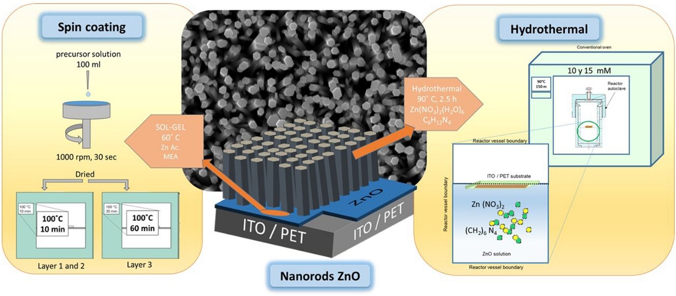
ZnO nucleation process on ITO/PET substratesPrior to the ZnO growth process, ITO/PET substrates must be prepared with a ZnO coupling layer using a ZnO seed solution through the solgel method. Zinc acetate dehydrate [Zn(O2(CCH)3)2 (H2O)2] (JT Baker, 99.0–101%), isopropyl alcohol (JT Baker, 95%) and ethanolamine [C2H7NO] were used as a starting material, solvent and stabilizer, respectively. The molar ratio of zinc acetate dehydrate and ethanolamine was 1:1 and the concentration of zinc acetate was 10 and 15mM [25]. At the same time, this dissolution was subjected to constant stirring for 2h at 60°C to promote the complete dissolution of the precursor reagent and obtain a homogeneous solution, which was aged for 24h to obtain the ZnO seed solution, as shown in Fig. 1(a). It is expected that small zinc-oxo-acetate oligomers will form in the initial stage, starting from the gradual forced hydrolysis of soluble complexes, such as Zn, during aging [26].
, (a) dissolution of dehydrated zinc acetate in isopropyl alcohol and (b) layer deposit and drying process with seed solution.")
ITO/PET substrates were coated with the ZnO seed solution to get a seed layer (SL). The procedure followed for this consisted in attaching the substrate at the holder of the spin coating equipment, then putting 100μl of the ZnO seed solution on the ITO/PET substrate and starting the spin coating process at a rate of 1000rpm for 30s. Samples of ITO/PET substrates coated with the coupling layer were dried at 100°C for 10min. This coating/drying process was repeated two more times, and finally, the drying time for the third layer was 30min at 100°C. The ZnO seed layer process scheme described above is shown in Fig. 1(b).
ZnO hydrothermal growth process onto the ZnO seed layerFor the growth of the ZnO nanorods, the hydrothermal solution (HT) was prepared by mixing an equimolar aqueous solution of zinc nitrate hexahydrate [Zn(NO3)2·6H2O] (Sigma–Aldrich, 98%) and hexamethylenetetramine [C6H12N4] (Sigma–Aldrich, 99%). The solutions were prepared at concentrations of 10 and 15mM. The substrate coated with the ZnO seed layer was immersed in the corresponding solution of zinc nitrate hexahydrate and hexamethylenetetramine. The substrate was placed face down inside onto the Teflon vessel reactor, to avoid a disturbance in hydrothermal growth. Subsequently the Teflon vessel reactor was placed in a conventional oven, as can be seen in Fig. 2. When the samples reached 90°C, the growth time was 150min. After the hydrothermal process, the samples were rinsed in deionized water and dried at 100°C in an oven for 10min.

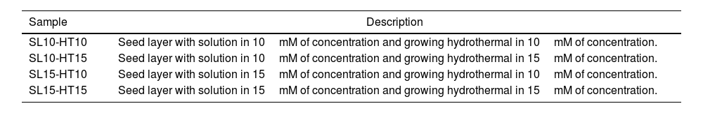
The samples obtained are listed in Table 1, where SL meaning seed layer and HT is Hydrothermal, 10 and 15 refers to concentration in solution by seed layer and hydrothermal, respectively.
Nomenclature of samples obtained.
| Sample | Description |
|---|---|
| SL10-HT10 | Seed layer with solution in 10mM of concentration and growing hydrothermal in 10mM of concentration. |
| SL10-HT15 | Seed layer with solution in 10mM of concentration and growing hydrothermal in 15mM of concentration. |
| SL15-HT10 | Seed layer with solution in 15mM of concentration and growing hydrothermal in 10mM of concentration. |
| SL15-HT15 | Seed layer with solution in 15mM of concentration and growing hydrothermal in 15mM of concentration. |
The photographic image (Fig. 3), shows a ZnO/ITO/PET hydrothermal growth sample obtained with a10mM solution precursor onto a ITO/PET flexible substrate, as could be see the drying treatment did not affect the flexibility properties of the ITO/PET substrate.
Structural and morphological characterization
The ZnO crystalline structure was investigated by X-ray diffraction (XRD) using an X-ray diffractometer (Panalytical model Empyrean), Cu-K-radiation and λ=1.54Å. The ZnO size, shape and orientation was analyzed by field emission scanning electron microscopy (FESEM) in a microscope (Bruker model Nano Gmbh).
Results and discussionCrystalline structure of thin ZnO films by X-ray diffraction and its correlation with Gibbs free energyEvidence of the crystallinity degree of ZnO films on a flexible ITO/PET substrate is shown in the XRD pattern, provided in Fig. 4(a). One intense signal is centered at 26 2θ, which corresponds to the PET substrate. In addition, there are four main peaks located at approximately 34.45°(2θ), 36.30°(2θ), 47.50°(2θ) and 62.90°(2θ), corresponding to the compound ZnO, which is consistent with the values of the standard ICCD card no. 00-036-1451. All films were poly-crystalline and presented the highest peak at approximately 34.45° (2θ) in the plane (002).
 derived by sol–gel and after a hydrothermal synthesis at 15mM with a PET-associated peak (b) derived by sol–gel and after a hydrothermal synthesis at 10 and 15mM in the hydrothermal solution.")
Fig. 4(b) shows the XRD patterns of ZnO nanorods, obtained by sol–gel and subsequent hydrothermal synthesis. No intermediate characteristic peaks of impurity of Zn(OH)2 were observed [17], indicating that the precursor material is dissolved within the ZnO core (ICCD card no. 38-0385). The diffraction peaks measured for the ZnO nanorods at 10 and 15mM show Bragg peaks for films corresponding to the (002) and (101) planes, with a hexagonal structure, confirming their wurtzite-like crystalline structure, which is consistent with the 00-036-1451 ICDD card for ZnO.
The peak at 25.92 2Θ degree correspond to the diffraction peak of the PET substrate coated by ITO [27]. According to the X-ray diffraction measurement, the seed layer is not crystalline.
The degree indicates the preferential growth along the [002] direction, corresponding to texturization on the C axis [28], because the c-plane, perpendicular to the substrate, is the most densely packed and thermodynamically favorable in the wurtzite structure. The average network parameters were a=3.20Å and c=5.22Å, with a ratio of c/a=1.63. The quality of the c-orientation of the ZnO thin films was calculated by the relative texture coefficient (TC, measures the relative degree of preferred orientation during the crystal growth of the material) through Eq. (1)[29].
where TC002 is the relative texture coefficient of diffraction peaks (002). The terms I002, I101, I102, and I103 are measured diffraction intensities due to the (002), (101), (102), and (103) planes, respectively, while I0020, I1010, I1020 and I1030 are the standard intensities, according to the ICCD card number 00-036-1451, measured from randomly oriented samples. The calculated values of TC for the films are shown in Fig. 5, a behavior of the texture coefficient is shown as the concentration changes. It was observed that the TC values of the crystalline ZnO layer in the (002) direction are greater and increases as the concentration in the seed layer increases, which means that the nanostructures prefer to grow in this direction, in comparison with the other directions (which is consistent with the SEM images). Additionally, Fig. 5 shows that the TC values for planes (101), (102) and (103) vary as the concentration increases, without being greater than plane (002).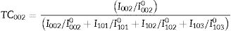

The crystals size was calculated using the Debye–Scherrer Eq. (2):
where λ is the wavelength of the X-ray beam, θ is the diffraction angle, D is the crystallite size, k is the form factor, and β is the full width at the Half Maximum (FWHM) peak. The average crystalline size for the ZnO nanorods at 10 and 15mM was 27.41nm, as listed in Table 2. An almost linear trend in the grain size is observed for each concentration.
The growth mechanism proposed is that the ZnO nanocrystal growth process is divided into two parts: (i) nucleation, which is the initial process through which a crystal is formed from a solution, a certain number of ions, atoms or molecules are organized into a characteristic solid crystalline pattern, and additional particles are deposited that promote the crystal growth [30]; and (ii) the growth process. This study focuses on the nucleation from a solution. In a solution with a constant temperature and pressure, the nucleation is directed by the difference in free energy between liquid and solid phases [31]. The growth of nuclei is generated randomly and spontaneously to form a new phase by homogeneous nucleation. In general, the free energy, between a solid particle of a solute (is assumed to be a spherical radius r) and a solute in a solution is equal to the sum of the surface free energy, ΔGS, meaning the free energy of a particle's surface, ΔGS is a proportional magnitude to r2, so it is a positive amount. ΔGV is a negative amount proportional to r3. Thus,
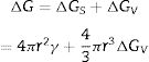
where ΔGV is the free energy change of transformation per volume and γ is the interfacial tension, that is, between the crystalline development of the surface the supersaturated solution in which it is located. The right-side terms of Eq. (3) have an opposite sign, and they are directly related to r. Hence, the free energy of the formation ΔG passes through a maximum value. According previous studies [32,33] the growth of nanorod nucleation, obtained from the formation of the initial nucleus in the hydrothermal process, may be due to the growth of nanoparticles either on the surface or on the edge of grain. The model proposed by Demes et al. 2019 involves a nucleation on the surface of the nanoparticle (on the entire surface or a structural defect). According to Eq. (4), the calculated Gibbs free energy was calculated for the grain size obtained in our experiments:
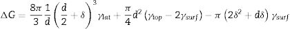
where d is the initial diameter of the nucleus, δ is the initial thickness increment of the nanoparticle, γlat is the surface energy of the side wall, which, according to Claeyssens et al. 2005 [34] and other researchers, has values in the range of 0.8–1.1Jm−2, and γtop is the surface energy on the top of the planes, which, according to the literature, has a range between 1.2 and 1.6Jm−2, for our experiment the selected values were γlat=0.96Jm−2 and γtop=1.49Jm−2. Assuming that γsurf is the surface energy of the ZnO nanoparticle, as has been reported by Li et al. 2012 and other researchers, the value for the hydrated ZnO is 1.42±0.21, γsurf. The Gibbs free energy ΔG is found to depend on the nucleus diameter, when the nucleation starts the initial thickness (δ) increment of the nanoparticle is related to the matter that the growing particle receives. Therefore, according to the literature, growth can be achieved by adding atomic layers of Zn or O, with growth along the c-axis, supposes that at 0.06nm δ≈c/8, 0.20nm δ≈(3/8)c, or adding ZnO groups, which infers 0.26nm δ≈c/2 and 0.52nm δ≈c[32]. The results in Fig. 6, show a general description as a function of the nucleus diameter (d) when δ vary and γlat=0.96Jm−2 and γtop=1.49Jm−2, in the first instance, when ΔG>0 for all nucleus sizes, the nanoparticles are stable and do not grow. While for ΔG<0; δ take values of 0.06, 0.20 and 0.26nm and initial diameter (d) is 10, 22 and 30nm respectively, being these crucial diameters to ZnO nanorods grow on the C axis.
Morphological analyses and ZnO layer thickness calculate
The FESEM analysis was performed to determine the morphology of the synthesized structures as well as the size and orientation of the nanorods. In Fig. 7 shows the morphological properties of the ZnO nanorods grown on a flexible PET/ITO substrate, Fig. 7(a) corresponds to the concentrations of 10mM in seed solution SL and 10mM in HT, Fig. 7(b) is 10mM in SL and 15mM in HT, Fig. 7(c) is 15mM in SL and 10mM in HT, finally 7(d) is 15mM in SL and 15mM in HT. All samples showed growth of hexagonal nanorods, where it is possible to observe two kinds of arrangement: (i) Fig. 7(a) and (c) with average diameter of 50 and 80nm respectively, also shows partial vertical growth of nanorod with dimensions of about 500 –700nm lengths, (ii) Fig. 7(b) and (d) shows complete growth on the c axis of nanorods, moreover, the top of the nanorods shows a hexagonal facet, indicating that the nanorods are single crystals growing along the [002] direction. The calculated average diameter is 165 and 195nm respectively and lengths between 0.4μm and 1μm.
 ZnO nanorods with 10mM for ZnO seed layer and 10mM in HT, (b) ZnO nanorods with 10mM for ZnO seed layer and 15mM in HT, (c) ZnO nanorods with 15mM for ZnO seed layer and 10mM in HT and (d) ZnO nanorods with 15mM for ZnO seed layer and 15mM in HT.")
FESEM Images ZnO nanorods obtained by hydrothermal synthesis, (a) ZnO nanorods with 10mM for ZnO seed layer and 10mM in HT, (b) ZnO nanorods with 10mM for ZnO seed layer and 15mM in HT, (c) ZnO nanorods with 15mM for ZnO seed layer and 10mM in HT and (d) ZnO nanorods with 15mM for ZnO seed layer and 15mM in HT.
A high density of growth of nanorods with a homogeneous coating on the entire surface can also be seen. The nanorods with greater dimensions were obtained with the conditions SL15-HT15 (Fig. 7c). These changes in growth of ZnO nanorods can be attributed to increase in concentration at the hydrothermal process stage, when the concentrations of Zn2+ and OH− reach the critical value of the supersaturation and the nucleation begins the polar top planes attract more ion (because these faces [001] are polar) contributing to faster growth the vertical aligned ZnO nanorods [20]. Based on the above, it is reasonable to expect that nanorods orientation is determined by nucleation and growth of the first few layers of atoms on ZnO seed layer, the greatest disposition of Zn2+ and O2− ions on the surface of the substrate results in a well-defined hexagonal morphology (as observed from in Fig. 7). This is because of growth along the c-axis or (001) direction is faster compared to the growth along the other directions [35]. The growth rate trend (ν) for nanorod faces is as follows ν [001]>ν [101]>ν [100] [36], this property allows the fastest growth occurs along the c-axis. To minimize the free surface energy, the nanorods have a tendency to grow along their the c-axis more rapidly than along their plans as the polar faces promote electrostatic interactions among the ion species in the solution [37].
These FESEM images obtained from the HT treatment and with the concentrations described, are conclusive that the concentration of the precursor solutions of ZnO is a decisive factor in the size of the nanorod structure and its orientation. Being the ZnO nanorods obtained with a concentration of 15mM in HT, those that present the best alignment. It is also observed that the growth time of 150min at 90°C and 100°C for drying ZnO film, do not affect the orientation of growth.
ZnO nanorod layer adherence onto substrate was evaluated using the ASTM D 3359-17 standard test, the value adherence obtained was classified as 3, as observed in Fig. 8a. Fig. 8b shown a uniform layer of ZnO nanorods, the approximate thickness of the seed layer and of nanorods is also illustrated.
Conclusions ASTM D3359-17 classification 3 in adherence test, (b) layer thickness of ZnO nanorod growth.")
The hydrothermal method of synthesizing ZnO nanorods using a ZnO solgel seed layer on ITO/PET substrates showed good results as a low temperature method for obtaining well aligned ZnO nanorods. ZnO well adhered thin films with nanorods shapes oriented toward and perpendicular to the plane of the ITO/PET substrate, were obtained (plane 002) for 10 and 15mM solutions precursor concentrations. In this way, a route for synthesizing ZnO thin films with a single-like crystalline structure is demonstrated. The XRD results provide evidence that the synthesized ZnO structures are composed of hexagonal wurtzite-like crystal structures. It is important to mention, that by XRD analysis, the ZnO sample that presented the highest intensity with a concentration of 15mM for the seed layer and 10mM in the hydrothermal treatment, we assume that could indicate major ZnO nanocrystal growth. With the Gibbs surface-free energy model, it was possible to understand that the minimum diameter size of the ZnO nanorod nucleus is between 10 and 30nm. The synthesis route is a reproducible at 90°C which is a low-temperature process, able to modulate the growth of ZnO nanostructures toward a desired morphology by controlling the synthesis parameters.
The present research was funded by Project CB CONACYT 2015 number 256221. Authors also thank to Scholarship number 722545 for the doctoral thesis of Fabiola Gomez, the postdoctoral scholarship provided by PRODEP to Dr. José Cervantes, with reference number SSA-5423/19.
The following are the supplementary data to this article:

