


The refractory used in the pyrometallurgical furnaces is periodically replaced because of wear. Refractory wear is determined by contact with the molten phases that interact with the refractory, in which chemical reactions are significant. Molten phases penetrate the refractory structure through the open porosity, this condition often being the first step in the complex phenomena of wear in these materials.
In this work, the infiltration of Mg–Cr–O and Al–Cr–O industrial refractories by the molten phases in the copper-making process has been studied by adapting the sessile drop technique usually associated with wetting studies. An evaluation of the volume of liquid infiltration and the time needed to reach the maximum level were compared for three types of industrial refractories and three types of molten phases: fayalitic slag, matte and copper. An experimental analysis of the wetting behavior of those molten phases on the principal constituents of the refractories tested was developed to better understand the results.
El refractario usado en los hornos pirometalúrgicos sufre desgaste a lo largo de su vida de operación, por lo que debe ser reemplazado periódicamente. Este desgaste está provocado fundamentalmente por la interacción con las fases fundidas que interactúan con el mismo. Las fases fundidas penetran en la estructura refractaria a través de la porosidad abierta, siendo este primer paso en los complejos fenómenos de desgaste que se llevan a cabo en estos materiales.
Específicamente, en este trabajo se ha estudiado la infiltración de los refractarios industriales de Mg-Cr-O y Al-Cr-O por las fases fundidas del proceso pirometalúrgico de fabricación de cobre, mediante la adaptación de la técnica «sessile drop», la cual generalmente se encuentra asociada a estudios de mojabilidad. Los parámetros fundamentales a comparar han sido el volumen de infiltración y el tiempo necesario para alcanzar el nivel máximo infiltrado para tres tipos de refractarios industriales y tres tipos de fases fundidas (escoria fayalítica, mata y cobre). Además, de cara a comprender mejor los resultados obtenidos, se ha desarrollado un análisis experimental del comportamiento de la mojabilidad de esas fases fundidas sobre los principales constituyentes de los refractarios mencionados.
Copper is produced by hydrometallurgy (18%) and pyrometallurgy (82%) [1]. In pyrometallurgy, four steps are carried out to obtain copper from polymetallic sulphides [1–4]: smelting, conversion, fire refining and electrolytic refining. Smelting and conversion are oxidative processes that produce two immiscible liquids: the slag phase that contains Fe2SiO4 and Fe3O4, and the copper-enriched sulphide or metallic phase (matte with 50–70wt.% Cu in smelting and blister copper with 99–99.5wt.% Cu in conversion). Blister copper is fire-refined by injecting air into the bath to remove the residual S (ppm), and the resultant copper is cast to produce anodes (99.5wt.% Cu). Finally, the anodic copper is transformed into cathode copper (99.99wt.% Cu) by electrolytic refining (batch).
The furnaces used in this process are lined with refractories. The most widely used in the copper-making industry is the magnesia–chromite refractory [5,6], but alternatives such as alumina–chromite are emerging. During operation, refractory wear occurs as a consequence of the infiltration by the molten phases, chemical interaction between the molten phases and the refractory, and thermal and mechanical shocks. Refractory wear leads to high maintenance and operating costs.
The wear mechanism is a complex succession and superposition of phenomena; each can be analyzed independently, and in some cases, it is possible to identify the one responsible for the global degradation. Refractory materials are polyphasic with a defined chemical and crystalline structure for each constituent. The grains of these constituents remain cohesive thanks to the binder, in which the third constituent element to describe the refractory microstructure is the open porosity that forms during manufacture. The molten phases infiltrate the open porosity in accordance with certain physicochemical characteristics and, when this phenomenon occurs, it is the first step in the degradation of the lining across a range of furnaces and processes [5–8].
The infiltration of the refractory and its chemical interaction with the molten phases increases refractory wear in the vicinity of the liquid–solid interface. Both processes are influenced by the chemical composition and microstructure of the refractory. According to the literature [5,6,8] and previous works carried out by these authors [7,9], the infiltration modifies the microstructure of the refractory by filling the open pores and destroying the grain bonds. This infiltration causes the refractory to modify its physical properties and broadens the potentially reactive area where dissolution or any other type of chemical reaction between the molten phases and the refractory constituents can proceed. The result of those modifications leads to the detachment of the grain and/or to chemical degradation of the whole material.
In the copper-making process by pyrometallurgy, a reaction layer is formed on the hot face of the refractory, acting as a shield against additional infiltration; this reaction layer contains high Mg# olivine and iron-enriched spinel as a consequence of the reaction between the refractory constituents and the fayalitic slags. This reaction layer has physical properties that differ from the as-delivered refractory (mainly in density and thermal conductivity), so the spallation of this layer occurs during operation as a result of thermal and mechanical shocks [5–8]. Therefore, the internal areas of the brick become the new hot face in contact with the bath, so a new interaction between the molten phases and the refractory occurs, started by infiltration[10]. This cyclical effect is continuously repeated during the lifetime of the refractory, increasing refractory wear. It is widely accepted that in terms of the lining of reactors in the pyrometallurgical process of primary copper production, this cyclical process starts with the wetting and subsequent infiltration of different phases through the open porosity of the refractories [5,8].
The post-mortem analyses carried out on the refractory lining of Peirce Smith Converters and a Submerged Arc Furnace by these authors, accompanied by thermochemical calculations and simulations [7,9], manifest the importance of infiltration as a starting point in the degradation process of the refractory. Due to the highly complex infiltration process of porous refractories, controlled tests must be carried out to thoroughly assess the infiltration of a refractory by the molten phases in the pyrometallurgical process [8,11]. In this work, the spontaneous infiltration of three industrial refractory substrates by molten phases sampled from industrial furnaces at Atlantic Copper (Spain) has been evaluated by adapting the sessile drop method. Two types of magnesia–chromite refractories and an alumina–chromite refractory were used. No previous works have been found in the literature comparing these types of refractories (mainly for alumina–chromite refractory).
FundamentalsThe channels of porous refractories are braided, their sections vary along any given channel, and their internal surfaces are rough [12]. However, the main features of the thermodynamics and kinetics of pore infiltration can be explained using the very simple configuration of a unique, cylindrically shaped, straight-line pore with a constant section area [8].
The equilibrium value of the rise in liquid in the capillary can be calculated by minimizing the variation in total free energy as a function of the rise, from the border of the pore to the maximum distance in the capillary. The total free energy depends on three components (Eq. (1)) [8]:
- -
The force required to overcome gravitational forces when the distance changes from zero to the final infiltration point.
- -
The work done by the pressure applied when the front rises from the border to the final infiltration point.
- -
The change in the surface energy.

Eq. 1: Variation in free energy from the border (z=0) to the infiltration (z).where Po is the pressure applied on the liquid at the capillary entrance z=0. P the pressure of the vapor phase ahead of the infiltration front. σ is the surface energy of the melt. r is the radius of the pore. ρ is the density of the melt. θ is the equilibrium contact angle between the melt and the solid. z is the distance to the external border of the refractory.
At the equilibrium, the variation of the free energy for a differential infiltrated distance is zero [d(ΔG)/dz=0] so Eq. (1) becomes the following (Eq. (2)):
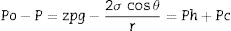
Eq. 1: Equilibrium state of Eq. (1). Ph is the hydrostatic pressure and Pc is the capillary pressure.
If the contact angle is θ<90°, the capillary pressure helps the liquid to infiltrate (wetting liquids; θ=0° means perfect wetting), whereas if θ>90°, external pressure is required to infiltrate (non-wetting melts) [8]. Oxygen in furnace atmospheres leads to a significant decrease in the contact angle [13]. For wetting systems, the capillary rise occurs spontaneously without any applied pressure [14].
Deviations from the ideal conditions must be considered for theoretical calculations. The roughness (even some microns) and heterogeneities on the surface (and pores), and the size distribution and non-cylindrical shape of the pores, are examples of non-ideal conditions. Empirical methods are used to evaluate the deviation from ideality [8].
The infiltration of the refractory by a molten phase can be accompanied by reactions which modify the chemistry of the liquid (viscosity, surface tension), the geometry of the pores and the formation of new phases [14,15]. These changes have considerable influence on the infiltration process because the kinetics and the driving force are modified. This influence can facilitate the infiltration but, in other cases, the effect is just the opposite because of the formation of reaction products that can act as a shield, thus avoiding further infiltration.
MethodologySessile drop experiments on refractory substrates have been carried out in his work. The sessile drop technique is based on the measurement of the contact angle (θ) between a liquid and a solid. It allows the calculation of the surface tension between the liquid and substrate using different mathematical descriptions, such as the Young Laplace equation that relates the contact angle to this fundamental magnitude. To achieve representative and accurate results, especially with molten phases over different types of substrates, this technique must carefully consider a series of characteristics for the experiment: the rugosity of the substrate, the mass of the liquid (it must be low), the effect of gravitational forces (negligible against surface forces) and the substrate (ideally monocrystalline, so the influence of the grain boundaries on the measurement can be minimized). This defect can influence the contact angle value; for example, the triple line falls directly on one grain boundary and the solid liquid system could be reactive.
After the experiment, the data collected, on the evolution in the time of θright and θleft, require rigorous analysis to evaluate the dynamic and difference, if any, between the two angles [8,16]. In this experimental study, we have used this technique for a very different purpose, and the experimental results presented here focus on the evaluation of surface properties.
The contact angle is determined by software that uses the analysis of the image projected by the system studied (a molten phase over a refractory). This software determines the shape and contour of the image and different geometrical parameters of the liquid. The evaluation of the gray scale values of the recorded image allows the detection of the so-called baseline (the contact between droplet and solid) and the drop outline.
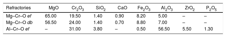
The industrial refractory substrates used in this work were designated by their industrial names: magnesia–chromite (electrofused “ef” and direct bonded “db”) and electrofused alumina–chromite. These materials are poly-constituents and each of constituent is polycrystalline. As well as these characteristics, the refractories have an open porosity, which is the main interest of this study focused on the infiltration of molten phases through this porosity. The molten phases used were matte from a flash smelting furnace (62% Cu), and slag and blister copper from the conversion stage (Peirce Smith Converter; PSC) (Table 1).
Composition of the substrates and molten phases used in this study. Units in weight percent (wt.%).
| Refractories | MgO | Cr2O3 | SiO2 | CaO | Fe2O3 | Al2O3 | ZrO2 | P2O5 |
|---|---|---|---|---|---|---|---|---|
| Mg–Cr–O ef | 65.00 | 19.50 | 1.40 | 0.90 | 8.20 | 5.00 | – | – |
| Mg–Cr–O db | 56.50 | 24.00 | 1.40 | 0.70 | 8.80 | 7.00 | – | – |
| Al–Cr–O ef | – | 31.00 | 3.80 | – | 0.50 | 56.50 | 5.50 | 1.30 |
| Molten phases | Cu | S | SiO2 | Al2O3 | CaO | Fe | Pb | Fe3O4 |
|---|---|---|---|---|---|---|---|---|
| Matte | 62.97 | 22.40 | 0.54 | 0.01 | 0.35 | 12.97 | 0.31 | 3.00 |
| CPS Fe slag | 47.56 | 0.15 | 9.20 | 0.40 | 0.70 | 19.34 | 1.98 | – |
| Blister copper | 99.2 | – | – | – | – | – | – | – |
Standard equipment was used in the experimental study: an EM301 heating microscope (Fig. 1) (Hesse Instruments; Germany). This set-up is mainly used to measure contact angles and characteristic temperatures of materials at high temperatures. In this case, the data provided by the image analysis software were used to determine the volume evolution of the molten phases on the refractory material.
. electrical eating furnace (MoSi2 elements), heating control system, gas inlet for control of the atmosphere, light source and intensity control, high-resolution camera for image capture, computer for overall control and image analysis software.")
EM01 heating microscope used in the experimental study (Hesse Instruments; Germany).
electrical eating furnace (MoSi2 elements), heating control system, gas inlet for control of the atmosphere, light source and intensity control, high-resolution camera for image capture, computer for overall control and image analysis software.


The preparation of the substrate started with the cutting of a sample from an as-delivered industrial brick. The shape and size were square, measuring about 10mm×10mm with a thickness of 2mm. These pieces were then polished to scrabble any irregularity. Due to the heterogeneity of the macrostructure composed of different materials, some fine dust could have penetrated the sample due to its porosity. To avoid this risk an ultrasonic bath with acetone was applied for 3min.
The molten phase was taken from a bulk solid sample previously ground and provided by the Atlantic Copper Smelter. A representative sample was obtained and then pulverized to 100% under 0.149mm. From this material, a sample within the 5–10g range was obtained and, after applying a light humectant, a cylindrical briquette of about 1.5mm×3mm was prepared in a press. The blister copper being a metallic material, a mechanical preparation was made to obtain a cylinder using a precision lathe.
The various liquid samples were placed over the substrate in the furnace and heated in a purified N2(g) atmosphere. The heating cycle consists of a first step from room temperature to 800°C at a rate of 60°C×min−1, then up to 1180°C at 60°C×min−1 rising to 1350°C at 10°C×min−1. The temperature was maintained at this level for 30min, enough time to array the equilibrium condition for the infiltration phenomena.
The contour images of the molten phase – substrate systems were recorded online, and their evolution were saved to a video file. The software for image analysis delivers geometric parameters of the shape of the projected image against time: baseline, height, and left and right contact angles. Furthermore, based on this information, the software estimates the characteristic temperatures defined in the standard pyrometric cone test. An example of the images of the evolution of the system from room temperature to the end of the experiment are shown in Fig. 2.
Quantification of the volume of infiltration from the shape of the remaining liquid drop start, (b) formation of the sphere with the sample 100% melted, (c) formation of hemisphere and (d) final condition.")
The geometric parameters obtained from the image analysis software allow the evaluation of the liquid infiltration by comparing the volume of the melted sample at the beginning (t=0 when the shape represents a complete melting condition of the sample) and the evolution of the remaining volume over the substrate. To develop this quantification, a relation between the geometric parameters and the volume is needed. Sommers and Jacobi [17] proposed a method to calculate the volume according to the following equation as a function of the contact angle (θ):
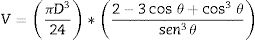
This approximation is appropriate for the evaluation of the volume because all the liquids tend to wet oxides, so a condition in which the liquid volume will always be represented by a semi-sphere skullcap is to be expected.
Microstructural characterizationA microstructural characterization of these commercial refractories was carried out using Scanning Electron Microscope (SEM) and EPMA. With the BSE images obtained, the porosity values were determined and compared with the values given by the supplier.
For this purpose, the ImageJ 1.50i scientific imaging software was used to set the porosity of the refractories. ImageJ is an open source Java image processing program that can display, edit, analyze and process images [18,19].
ResultsThe heterogeneous systems led to a response according to the relative size of the liquid sample and the elements of the microstructure: grain size of the constituents and pore size. In this case, when a sample of a few grams (5–10g) of liquid interacts with different interfaces, the result will strongly depend on which type of constituent the liquid makes contact with. Indeed, the size of the liquid drop formed while melted is close to the order of magnitude of the macrostructure of the refractory. The same is valid when the infiltration occurs, and the liquid flows into the channels according to the behavior of the melt with the specific solid with which it comes into contact.
The experimental dynamic evolution of the infiltrating volume on a substrate, as a function of the values measured as r and θ, has indeed produced variations for the same conditions, reflecting the particular conditions of the experiment. As examples, Figs. 3–5 show the experimental curves for each of the molten phases that reflect this characteristic.
 on MgCr ef. Red line and points correspond to the percentage of liquid infiltration. The second graph shows an experiment when it was not possible to acquire reliable information.")
 on MgCr db. Red line and points correspond to the percentage of liquid infiltration.")
 of (a) Al–Cr–O ef and of Mg–Cr–O db (b). Red line and points correspond to the percentage of liquid infiltration.")
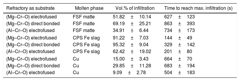
To calculate a final value for each molten phase/substrate couple, a minimum of five repetitions were carried out to produce a smooth curve, such as in the examples given (Figs. 3–5). Even then, the average and standard deviation for the volume of infiltration and the time taken to reach this level of infiltration (Table 2) amount to a non-negligible dispersion.
Results of the infiltration of the liquid (as vol.% of the initial) and the time taken to reach this condition.
| Refractory as substrate | Molten phase | Vol.% of infiltration | Time to reach max. infiltration (s) |
|---|---|---|---|
| (Mg–Cr–O) electrofused | FSF matte | 51.82±10.14 | 627±123 |
| (Mg–Cr–O) direct bonded | FSF matte | 69.19±25.21 | 863±393 |
| (Al–Cr–O) electrofused | FSF matte | 34.91±6.44 | 734±173 |
| (Mg–Cr–O) electrofused | CPS Fe slag | 91.22±7.03 | 144±49 |
| (Mg–Cr–O) direct bonded | CPS Fe slag | 95.32±9.04 | 329±142 |
| (Al–Cr–O) electrofused | CPS Fe slag | 62.42±19.02 | 201±80 |
| (Mg–Cr–O) electrofused | Cu | 15.00±3.43 | 664±70 |
| (Mg–Cr–O) direct bonded | Cu | 29.85±11.28 | 683±194 |
| (Al–Cr–O) electrofused | Cu | 9.09±2.78 | 504±183 |
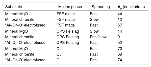
To generate more information on the fundamentals that drive the infiltration phenomena, and to explain the dispersion of the results, the apparent contact angle between the molten phases and the main pure phase constituents of the refractories were measured. The apparent contact angle is thus named because the system is not ideal when the surface properties can be determined. In this case, the substrates were three “pure” and dense constituents of the base materials used in the manufacturing of the refractories: mineral MgO and mineral chromite, and electrofused Mg–Cr–O. None of these materials, even the polycrystalline without porosity, are pure compounds, so the measurement is the determination of θ (each raw material's surface interaction with the molten phase).
The methodology used for these experiments was the same as that in the infiltration experiments, but in this case the result was the contact angle between the each of the same three molten phases and these substrates. The heating rate was 20°C×min−1 from room temperature to 1180°C, and 10°C×min−1 to 1350°C. Fractures appeared in the mineral chromite under these conditions. The problem was solved by prior thermal treatment at 70°C for 48h.
Two types of behavior were clearly identified regarding the spreading kinetic: a stable contact angle was first obtained with good concordance between θright and θleft and, in some cases, the spreading kinetic was observed to be slower, with less concordance between the two angles. Fig. 6 shows these different dynamics.
; Mineral Chromite and matte (b); Mineral Chromite and CPS Fe slag (c); electrofused Al–Cr–O and Cu (d). Red points are θright and blue points θleft.")
A summary of these results is shown in Table 3.
Results of the liquid infiltration percentage, and the time taken to reach this condition.
| Substrate | Molten phase | Spreading | θe (equilibrium) |
|---|---|---|---|
| Mineral MgO | FSF matte | Fast | 44 |
| Mineral chromite | FSF matte | Slow | 12 |
| “Al–Cr–O” electrofused | FSF matte | Fast | 67 |
| Mineral MgO | CPS Fe slag | Slow | 14 |
| Mineral chromite | CPS Fe slag | Fast/slow | 9 |
| “Al–Cr–O” electrofused | CPS Fe slag | Fast | 52 |
| Mineral MgO | Cu | Fast | 70 |
| Mineral chromite | Cu | Fast | 69 |
| “Al–Cr–O” electrofused | Cu | Fast | 74 |
Microstructural characterization was carried out for better support of the results. The BSE images of the microstructural characterization (Figs. 7 and 8 as examples) were processed using the ImageJ software. The results show that the porosity of the Al–Cr–O refractory is within the 8–12% range, of the Mg–Cr–O ef is 14–16% and of the Mg–Cr–O db is 16–18%.
 and the image processed by ImageJ (right). Pores in black. AZS: electrofused Al2O3–ZrO2–SiO2; E-Al: electrofused alumina; E-AC: electrofused alumina–chromite; Al–Cr–Si: electrofused alumina–chromite–silica.")
 and the image processed by ImageJ (right). Pores in black. Mgs: magnesia; EMC: electrofused magnesia–chromite; Chr: Chromite.")
In the case of the Al–Cr–O and Mg–Cr–O ef, the bonding between the constituent grains are mostly direct. By contrast, in the case of the Mg–Cr–O db in many cases intergranular phases are located between the grains.
From the BSE images, we conclude that in the case of the Al–Cr–O refractory (Fig. 7), the most abundant phase is the electrofused alumina–chromite–silica (Al–Cr–Si). This phase has crystals of alumina–chromite and large crystals with very high alumina content (>99.0wt% Al2O3; E-Al in fig. 7) rounded by alumina–chromite (E-AC). Electrofused Al2O3–ZrO2–SiO2 (AZS) grains are another constituents of the microstructure of this refractory type (Fig. 7); it present a matrix of alumina–silica and a dispersed phase with high zirconia content. Most of the grains are present without intergranular regions (no interphases between them). The pores are dispersed.
In the case of the Mg–Cr–O refractories (Fig. 8), chromite spinel (Chr) [Mg(Cr,Fe,Al)2O4] are as large crystals of and as secondary chromite within intergranular areas. The magnesia is as sintered magnesia grains (Mgs), mostly rounded by an external ring of electrofused magnesia–chromite. The electrofused magnesia–chromite (EMC) is formed by a magnesia matrix and chromite as dispersed phase. Mainly in the case of the Mg–Cr–O db, monticellite [CaMgSiO4] is located in intergranular areas. Monticellite does not enable direct bonding between the refractory grains, forming a weak point to face off chemical attack from the molten phases. Pores are homogeneously distributed along the microstructure of the refractory material.
Analysis and discussionAs shown in Eq. (1) the contact angle is a driving force that boosts, or halts, the infiltration process. From this consideration, the slag is the molten phase most likely to infiltrate the refractory microstructure, as the contact angles with the pure compound constituents of the refractory represent an extended wetting behavior. These conditions are widely reported in the literature: liquid oxides tend to wet solid oxides [13]. The results for the mineral MgO-slag couple present a slow spreading kinetic, suggesting that the spreading is controlled by the chemical reactions between the substrate and the molten slag. The same condition is observed in the interfacial interactions of mineral chromite and slag. In this case, the spreading kinetic is between a fast and slow process (θe reached after 150s), and the final contact angle, θe, is very low, presenting a complete wetting behavior that greatly facilitates infiltration. The chemical interactions between the substrate and molten slag that explain the slow spreading are represented by the dissolution into the slag of the constituent oxides of the solid compounds tested. The MgO in all cases can be dissolved in the fayalitic slag forming high Mg# olivine, and the chromite ore (spinel) incorporates iron into its structure to form iron-enriched spinel; this was demonstrated by the post-mortem analysis of industrial materials and thermochemical calculations [5,7,9]. Regarding the interaction with slag, the “Al–Cr–O” material seems to respond better, to the extent that the contact angle is significantly higher than the other two substrates analyzed. The “Al–Cr–O” material is promising as a constituent element of refractory material, inducing better characteristics to stop infiltration than those of the mineral MgO and mineral chromite. These good characteristics extend to the matte interaction, where the contact angle measured is significant, in this case presenting a low wetting behavior that compares to the behavior observed in metallic Cu. These qualitative results allow us to propose the hypothesis that electrofused materials respond better to the infiltration process regardless of the molten phase in contact.
It was expected that Cu would have the fewest wetting conditions on the oxides as Cu-oxide systems are not wetting systems (θe over 100°) [20]. In this case, the θe measured was about 70°. This difference could be due to the fact that the experiment, even using the sessile drop method, did not focus on the determination of the surface properties of a liquid/solid system, so the conditions required for such types of measurement were not considered. One main difference is that the polycrystalline substrate (industrial material) has different constituents, and it is important to note that the designation of the name corresponds only to an identification associated to the main constituent.
The infiltration results of the molten phases on refractories have a wide dispersion (Table 2), but a relation to the wetting behavior of the main constituents can be clearly identified.
As explained, the fayalitic slag from the PSC has an almost complete wetting behavior on the mineral MgO and mineral chromite. This condition clearly explains the complete and faster infiltration on the industrial refractories that have these main constituents. The same direct relation between the wetting behavior and the infiltration results can be identified in the metallic copper: less wetting behavior on the main constituents led to lower infiltration on the industrial refractories.
Based on the qualitative results obtained in this work, the three different refractories can be classified according to the ease (or difficulty) of infiltration by the molten phases used in this study. The classification proposed is the following: electrofused Al–Cr–O is the most resistant to infiltration, followed by electrofused Mg–Cr–O and finally, direct bonded Mg–Cr–O as the refractory with the lowest performance.
The dispersion of the results on the level of infiltration and the time needed to reach this condition can be related to the heterogeneous microstructure that each of the refractories tested. Due to the size of the infiltration test (sessile drop technique), the extension of the liquid can lead to interaction, preferably with one of the constituents of the refractory, which varied in each test according to a random condition. This experimental characteristic, even though far from the real conditions of infiltration phenomena at industrial scale, allows us to make a precise and quantitative analysis of the phenomena of the fundamentals that drive the infiltration. At industrial scale, more factors must be considered: for example, the metallostatic pressure the boosts the infiltration of the phases located in the bottom of the furnaces (Cu-rich phases) or the formation (or not formation) of new phases from the chemical interaction molten phase-refractory that could for a protective layer avoiding additional infiltrations (in the case of fayalitic slags) [5–9].
ConclusionThe infiltration behavior of molten phases of interest for the copper-making has been analyzed on three types of industrial refractory that line the reactors used in this process for primary Cu production. The infiltration tests were performed on industrial materials, and also included industrial molten phases. The choice of non-synthetic phases or more ideal materials was to generate representative conditions to enable us to simulate at laboratory scale the early stage of the complex wear and corrosion phenomena that take place on linings of the Cu pyrometallurgical reactors (found in previous works of the authors).
The adaption of the sessile drop technique is a good option for analyzing the fundamental mechanism of the infiltration phenomena, combining the quantification of the molten phase infiltration through the open porosity of an industrial refractory and analysis of the wetting behavior of the same molten phases on the pure main constituents of the refractories tested. Based on this proposed methodology, the fundamental infiltration formalism was qualitatively verified for the systems analyzed, allowing us to propose a classification of the materials based on the wetting characteristics of their individual constituents:
- -
For microstructure characteristics, electrofused materials perform better than direct bonded.
- -
The replacement of MgO by Al2O3 as main constituent improves resistance to infiltration.
Finally, the results analyzed for industrial conditions report a non-negligible dispersion; the explanation for this dispersion relates to the size of the experiment, in which the drop of the molten phase used in the “sessile drop technique” is close to the order of magnitude of the microstructure constituents of the industrial refractories.
Conflict of interestNone.

