


The properties of BaO–CaO–Al2O3–SiO2 (BCAS) glass seal materials reinforced with 5–30wt.% glass fiber are investigated. The seals are prepared by solid mixing process. The microstructure and phase content of the samples are studied. Mechanical properties are investigated by Vickers micro-hardness, nano-indentation and compression tests. The thermal properties of the samples are evaluated by conducting a dilatometry analysis. The electrical conductivity and leak resistance of the seal materials are measured at high temperatures. Increasing the amount of glass fiber in the composite samples decreases the magnitude of the thermal expansion coefficient. It is found the addition of just 5wt.% of glass fiber (GF5sample) increases the indentation fracture toughness of the seals by ∼280% without impairing other properties. It is also found that the GF5 sample has high electrical resistivity with the activation energy of 63.7kJ/mol and very low leak rate of 1.7×10⁻⁴sccm/cm at 750°C.
Se investigan las propiedades del sello de vidrio BaO-CaO-Al2O3-SiO2 (BCAS) con el 5-30% en peso de fibra de vidrio. Los sellos se preparan mediante un proceso de mezcla sólida. Se estudia la microestructura y el contenido de fase de las muestras. Las propiedades mecánicas se investigan mediante ensayos de microdureza, nano indentación y compresión de Vickers. Las propiedades térmicas de las muestras se evalúan realizando el análisis de dilatometría. La conductividad eléctrica y la resistencia a fugas de los materiales del sello se miden a altas temperaturas. El aumento de la cantidad de fibra de vidrio en las muestras compuestas disminuye la magnitud del coeficiente de expansión térmica. Se encuentra que con la adición de solo el 5% en peso de fibra de vidrio (muestra GF5) aumenta la resistencia a la fractura por indentación de los sellos en ∼280%, sin afectar otras propiedades. También se encuentra que la muestra GF5 tiene alta resistividad eléctrica con energía de activación de 63.7kJ/mol y una tasa de fuga muy baja de 1.7×10⁻⁴sccm/cm a 750°C.
Solid oxide fuel cell is a device converting chemical to electrical energy with high efficiency and low pollution [1]. A SOFC has at least three components, including an anode, electrolyte and cathode. The fuel (e.g. H2) is fed to the anode side, while the cathode is in contact with oxygen.
The two most common types of SOFCs are tubular and planar designs [2]. The planar solid oxide fuel cells (P-SOFC) have attracted much attention, especially due to their lower production cost and higher performance, as compared to the tubular design [2]. However, sealing various components of P-SOFC is one of the most important challenges hindering the commercialization of these cells [3]. In order to generate electricity with high performance, it is crucial to separate the fuel and oxidant (O2) effectively during the fuel cell operation period.
Seals are used to prevent leakage along with intermixing fuel and oxidant gases; both actions are crucial for the proper performance of P-SOFCs [4]. Sealing materials must have thermo-chemical stability under fuel cell working conditions; they should also be compatible with other SOFC components [4].
In addition, seals must be electrically insulating and have a thermal expansion coefficient matched with other SOFC components [4,5].
Various sealing materials have been developed for P-SOFC; these can be categorized into three groups: compressive seals, compliant seals and rigid bonded seals [6].
The rigid bonded seals are mainly based on glass and glass/ceramic materials that are softened at high temperatures; they bind different components of SOFC to each other [7]. The highly viscous glass at high temperatures wet SOFC components, creating a hermetic seal with self-healing and crack-blunting properties [7].
Glasses are of the most common materials for the sealing of SOFCs single cells and stacks; many different types of glass have been developed for SOFC applications, such as alkali silicates, alkaline earth silicates, borosilicates, aluminoborosilicates, barium calcium aluminosilicate (BCAS), etc. [3,4,6,8].
The BCAS glass is one the most common glass/ceramic sealants; there are many reports on the synthesis and characterization of such glasses for SOFC applications [9–13]. The properties of these glasses, such as glass transition temperature (Tg), degree of crystallinity, mechanical characteristics, electrical conductivity, etc., can be adjusted by controlling the composition and processing parameters [9–13].
In such glasses, BaO and SiO2 are network formers, while CaO is a network modifier. Al2O3 is an intermediate oxide that can act as a network former or modifier [14].
BCAS glass ceramics are used for joining and sealing different metallic and non-metallic materials. These glass materials are electrically insulating, creating gas-tight joints [15].
Seal materials must endure during the long life of SOFC; indeed, their mechanical properties and thermo-chemical stability are essential for the proper performance [3].
One of main drawbacks of glass seal materials is their low toughness, making them vulnerable to cracking during the SOFC thermal cycles operation.
Composite seals have attracted much attention in recent years due to the unique combination of the properties of the constituent phases [16,17].
In such materials, the overall properties of the seals can be adjusted by controlling the amount of the constituent phases and microstructure.
Different reinforcements, such as yttria stabilized zirconia fibers or powders [16], zirconia nano-particles [18], Al2O3[19], SiC fibers [20], mica [21,22], short alumino-silicate glass fiber [23] have been used for the preparation of glass composite seals for SOFC applications.
Glass fiber is one of the most common reinforcements for the preparing of various kinds of composite materials including glass–ceramics [24]. Due to the probable consistency of glass fiber with glass seals, this research aimed to investigate the properties of the BCAS/glass fiber composite seals. It was expected that the glass fiber would improve the indentation fracture toughness of the base glass seal. The composite seals have been prepared by mixing the short glass fiber and BCAS powder. The electrical, mechanical and thermal properties of the seal were studied.
Experimental procedureThe BCAS glass was synthesized by applying the melt quenching method. The weight percentages of the BCAS glass components included 56.4wt.% BaO, 22.1wt.% SiO2, 8.8wt.% CaO, 7.2wt.% B2O3 and 5.4wt.% Al2O3. The composition of the BCAS glass was chosen according to previously reported researches [25]. The weighted amount of the powders were pressed into the cylindrical pellet under the load of 200MPa.
All powders were purchased from Merck (Merck, Germany) and used as received. The pellets were then heated to 1330̊C with a heating rate of 10K/min and held at that temperature for 30min in a platinum crucible. The melt was then quenched in water and the prepared glass was crushed using a tumbling ball mill for 10h using alumina grinding balls. The powders were sieved down to ASTM634 sieve mesh number and the resulting powder with the average size of less than ∼20μm was milled again using a planetary ball mill for 20h at 300rpm, by alumina grinding media.
On the other hand, a short glass fiber (E-glass, Qingdao Material Company, China) with an average length of 25μm was mixed with the BCAS glass powder using a mechanical mixer in acetone.
The mixed powders were formed into a disk with a diameter of 10mm and a height of 5mm under the uniaxial pressure of 200MPa. Four different fiber glass/BCAS composites with 0, 5, 10, 20 and 30wt.% of the glass fiber were prepared, hereafter referred to as “GF”, followed by the weight percent of the glass fiber.
The specimens were sintered at different temperatures of 750°C, 850°C, and 900°C for 2h, with a heating rate of 200k/min.
The density of the sintered samples was measured by the Archimedes method. The particle size of the prepared BCAS glass was measured by applying the laser light scattering method (Litesizer 500, Anton-Paar, Austria).
The X-ray diffraction method (“XRD”, PW1730, Philips, Netherlands) was then used to study the phases present in the sample using the CuKα radiation. The XRD analysis was performed on samples in powder form over a 2θ range of 10–80°, step size of 0.05° and 50s of exposure time per step.
The microstructure of the sintered samples was studied by SEM (Mira3, TESCAN, Czech Republic). The sintered samples with the highest density were selected for further investigation.
The micro-hardness and indentation fracture toughness of the sintered specimens were measured by conducting the Vickers micro-hardness indentation test under the load of 100N on the polished surfaces. The Anstis formula was then used to calculate the indentation fracture toughness by measuring the crack length originated from the micro-hardness imprint [26]. The Young's modulus and nano-hardness of the prepared seals were evaluated by applying the nano-indentation method (NHT [3], Anton paar, Austria), using the method developed by Oliver and Phaar [27]. The maximum load, and holding time in nano-indentation test were 200mN and 10s respectively. The compression strength of the samples was measured according to ASTM C1424 on the samples (with a diameter of 15mm and thickness of 10mm) and the test was repeated for at least 10 samples.
The electrical conductivity of the sintered glass was measured by the electrochemical impedance spectroscopy (EIS) method at high temperatures and in the frequency range of 1MHz–7MHz, under air, by the impedance analyzer (VSP300, Biologic, France).
The thermal expansion coefficient of the samples was measured as a function of temperature, using the dilatometer (DIL 402, Netch, Germany) with a heating rate of 10K/min.
To prepare the seal paste, the glass powders were mixed with 20wt.% of the organic vehicle and ball-milled for 20h, using the zirconia grinding media.
The organic vehicle conferred the required fluidity to the paste; composed of 6wt% ethyl cellulose and 94wt.% terpineol.
The seal's performance under SOFC condition was tested using an anode-supported single button cell comprising Ni/YSZ, YSZ and LSM as the anode, electrolyte and cathode, respectively. At first, the anode support was prepared by the die compaction of Ni/YSZ and 10wt.% of graphite as a (pore former); this was followed by sintering at 1400°C for 2h. Electrolyte and cathode layers were applied on the anode substrate by employing the screen printing method. The resulting cell was sintered at 1200°C for 2h. The button cell was attached to the end of the alumina tube and the seal paste was applied around the cell. The Ag wires were connected to both sides of the cell with Ag paste (SOFC materials, USA); the resulting configuration was heated to 400°C to evaporate the binder in the seal with a heating rate of 5K/min. The I–V characteristic of the cell was recorded at 750̊C in 5vol%H2 in the N2 fuel gas with a flow rate of 40 SCCM on the anode side, and air on the cathode side by a potentiostat EIS.
To perform leak test, an alumina tube was closed at one end with the 8YSZ dense circular disk and sealed with the aid of the synthesized GF0 and GF5 specimen.
Argon gas at the constant pressure of 40kPa was then applied inside the alumina tube; the pressure drop was recorded at different time intervals with a temperature of 750̊C.
Results and discussionThe relative density variation (the ratio of the sintered density to the theoretical density) of different samples with the sintering temperature are presented in Fig. 1. The theoretical density of the composite (ρc) sample was calculated by considering the simple mixing rule, as shown below
where ρi and υi are the theoretical density and volume fraction of the glass matrix (g) and glass fiber (gf), respectively. The magnitude of the theoretical density of the glass matrix and glass fiber was assumed to be 3.93g/cm3h [25] and 2.49g/cm3[28], respectively.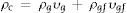
.")
As the sintering temperature was increased, the density of the samples was raised as well. However, the presence of the glass fiber seemed to inhibit the densification of the composite glasses, which could be related to the fact that glass fibers impeded the viscous flow of the matrix glass material. It has been reported that the presence of the rigid second phase in the glass matrix can generate stresses delaying the densification and/or creating cracks [29].
GF0 and GF5 samples were fully dense after sintering at 750°C in fact; they were not sintered at higher temperatures to prevent undesirable reactions. The sintering of GF10, GF20 and GF30 at temperatures higher than 850°C did not affect the relative density; so, this temperature could be considered as a proper sintering temperature. As high density is a one of the major requirements of the seal materials, the properties of the seals sintered at the proper temperature are presented in this paper.
The results of the XRD analysis of different samples are presented in Fig. 2. The as-prepared GF0 powder was completely amorphous (Fig. 2a), while the sintered samples showed some degree of crystallinity (Fig. 2b). The main crystalline phases in the sintered GF0 and GF30 are hexacelsian (BaAl2Si2O8, ICCD:01-088-1048) and crystalline silica (α-quartz), which are the typical phases in the BCAS glass materials [30]. The degree of the crystallinity of the GF30 composite is higher, which could be related to the higher sintering temperature and/or the presence of the glass fiber. It has been reported that the interface of the reinforcing fibers provides the nucleation site for the hexacelsian phase [20]. The crystallization of the hexacelsian phase is favorable for SOFC seals due to its high thermal expansion coefficient (CTE) [7]. The XRD patterns of GF5, GF10 and GF20 were nearly similar; so, it seemed that at least 30wt.% of the glass fiber was required to achieve the considerable difference in the XRD patterns.
, sintered glass at 750°C (b) and sintered GF30 sintered at 850°C (c).")
In addition, the XRD patterns of the samples confirmed the presence of minor phases which originated from the reaction between different components of the specimens. The crystallization of the hexacelsian phase in glass materials has been reported in many previous researches [31]. Hexacelsian is a metastable phase with a CTE of ∼10−8K−1 in the range of 30–1000°C it may be transformed to the monoclinic structure due to prolonged annealing, especially at higher temperatures [32]. The formation of the monoclinic celsian phase is detrimental for the SOFC seals; fortunately, this transformation is sluggish and quiet slow due to the necessary rearrangement of atoms through breaking and forming Al–O and Si–O bonds [31].
However, more investigations are required to study the combined effect of the glass fiber volume fraction and size along with the sintering temperature to quantify the kinetics of hexacelsian and the celsian phase formation.
The result of the particle size analysis of the synthesized glass powder after milling is presented in Fig. 3. The powder had an average particle size of 1.074μm and d50=1.18μm. The result of particle size analysis shows that the synthesized powder has a nearly bimodal size distribution with a small peak in the range of 50–60nm and a major peak in the range of ∼1000nm. The particle size has an essential role in densification [33], crystallization kinetics [34], and the required performance of the seal under the SOFC working condition. According to the previous researches, the reported mean particle size in this study is in the acceptable range for the glass seal materials [25,35].

The SEM image of the sintered samples is presented in Fig. 4. As can be seen, the microstructure of the GF0 sample (Fig. 4a and b) is homogeneous with high density, confirming the reported density. Fig. “4” and “4d” present the microstructure of the sintered GF30 composed of the glass fiber and hexacelsian needle-like phase homogeneously distributed in the matrix. In addition, some holes were present in the microstructure due to incomplete sintering. The accumulation of the hexacelsian phase in the region near the glass fibers, as shown in Fig. 3d and e would confirm the effect of the glass fiber on the enhanced nucleation process of this phase. It has been reported that the presence of SiC fiber in the glass matrix could improve the nucleation of the hexacelsian phase [20].
 and (b), GF30 (c) and (d), the hexacelsian phase at high magnification (e) and nano-indentation imprint on the GF0 sample (f).")
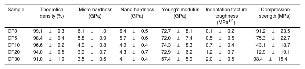
The mechanical properties of different specimens are presented in Table 1. The measured values of hardness and young's modulus of the GF0 sample are in good agreement with the previously reported data [11]. As the amount of the glass fiber was increased, the magnitude of hardness and Young's modulus of the composite seals were decreased, which could be related to their lower density and/or higher degree of the crystallinity of the composite samples. It is well known that the presence of porosity and crystallization of the amorphous glass materials could impair the mechanical properties [14].
The mechanical properties of the samples.
| Sample | Theoretical density (%) | Micro-hardness (GPa) | Nano-hardness (GPa) | Young's modulus (GPa) | Indentation fracture toughness (MPa1/2) | Compression strength (MPa) |
|---|---|---|---|---|---|---|
| GF0 | 99.1±0.3 | 6.1±1.0 | 6.4±0.5 | 72.7±8.1 | 0.1±0.2 | 191.2±23.5 |
| GF5 | 98.4±0.4 | 5.8±0.9 | 5.7±0.6 | 72.0±7.4 | 0.5±0.5 | 175.3±22.7 |
| GF10 | 96.6±0.2 | 4.9±0.8 | 4.9±0.4 | 74.3±8.3 | 0.7±0.4 | 143.1±18.7 |
| GF20 | 94.0±0.5 | 3.9±0.7 | 4.3±0.7 | 72.9±6.2 | 1.2±0.7 | 112.9±19.1 |
| GF30 | 91.0±1.0 | 3.5±0.6 | 4.1±0.4 | 67.4±5.9 | 2.0±0.5 | 98.4±15.4 |
Different relationships have been proposed to account for the dependence of mechanical properties on the volume fraction of porosities. Luo has reported that the hardness of the ceramic materials is evaluated by the indentation method, which can be described as [36]
where H0 the hardness of the fully dense ceramic and “H” is the hardness of the samples with a certain volume fraction of vacancies (P). According to the reported hardness values in this study, the steep decrease in the micro/nano-hardness of the composites could be related to both lower density and/or higher degree of crystallization, especially in the case of the GF30 sample. The presence of porosity decreased the rigidity of the glass network, thus lowering the hardness of the sample [37].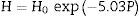
On the other hand, it has been reported that the development of needle-like phases along with the concomitant defect during crystallization declines the micro-hardness of the glass materials [14]. The reported values of measured hardness by micro-Vickers and nano-indentation methods are comparable.
The Young's modulus of the BCAS glass and E-glass fiber is ∼70GPa [11] and ∼70–80GPa [38], respectively. The presence of the glass fiber up to 20wt.% does not affect the elastic modulus of the composite samples, while that of GF30 was decreased considerably; this could be related to the lower density and/or higher amount of the hexacelsian phase. Different models have been proposed to account for the effect of porosity on the elastic modulus of ceramics [36].
Based on these models, given the porosity of the GF30 sample, around 4–5% of the elasticity modulus would be related to the presence of porosity. The effect of the crystallization of the amorphous matrix on Young's modulus should be, therefore, considered.
According to the data brought in Table 2, the indentation fracture toughness of the composite seals was enhanced precipitously due to the presence of the glass fibers. The indentation fracture toughness of GF5 is four times higher than that of the pure glass; the reason for this phenomenon could be the crack stoppage at the short fibers interface. The SEM image of the cracks originating from the corners of the nano-indentation imprint under the high applied loads is shown in Fig. 4f. The optical image of the indentation imprint on GF0 and GF5 samples is presented in Fig. 5. The optical image of the polished GF0 is represented for comparison. As can be seen, the cracks propagated in the glass matrix (Fig. 5b), while those encountering glass fibers were stopped at the interface due to the high strength of these fibers, as depicted in Fig. 5c. The indentation imprint on the glass fiber, as represented in Fig. 5d, did not show any crack propagation from the corners of the indentation triangle effect. This confirmed that the primary mechanism of the indentation fracture toughness improvement would be crack blunting at the interface of the high strength glass fibers. It should be noted that fracture toughness of ceramic materials depends on composition, phase content, processing method, measuring technique and, etc. The fracture toughness values reported in this study are comparatively lower than the previously reported data for usual glass seal materials [39]. However, the reported values are presented for the sake of comparison and investigation of the effect of glass fiber on fracture toughness.
, and the nano-indentation imprint of the GF0 (b), GF5 (c) and glass fiber (d).")
The compressive strength of the composite seal, as presented in Table 2, was decreased as the amount of the glass fiber content was increased. This would be related to the crack nucleation at the fiber/matrix interface, which promoted the fracture process. The glass-ceramic seals in SOFCs are usually under the compressive applied pressure of0.16MPa [19]; therefore, all of the seals synthesized in this study had the required strength level to ensure cell performance. It should be noted that the difference in CTE of different components of the composites could lead to residual stresses which affect the properties of the samples. However, more detailed studies are required to investigate the effect of residual stress on the properties of the composite seals in this study [15].
The results of the dilatometric analysis of the samples are presented in Fig. 6.
, GF5 (b), GF20 (c) and GF30 (d) specimens.")
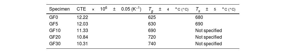
The estimated thermal expansion coefficient (CTE), glass transition temperature (Tg) and softening temperature (Ts) of the samples are presented in Table 2. The magnitude of CTE for the composite samples was decreased as the amount of the glass fiber was increased, the variation of which followed the simple mixture rule, as represented here:
where αi and υi are the CTE and vol.% of the glass matrix (m) and glass fiber (GF), respectively. It was assumed that the CTE values of the matrix and the glass fiber were 12.2×10⁻⁶K−1 (measured in this study) and 5.1×10⁻⁶K−1[40], respectively. It should be noted that the measured CTE of GF0 is in good agreement with previously reported [19,25].
According to the reported CTE values of SOFC components, the magnitude of the seals CTE was in the desired range required for the SOFC application [7]. However, another parameter crucial for the proper seal performance is the softening temperature Ts. The variations of CTE of the samples over prolonged 50 heating and cooling cycles were less than 5%, showing acceptable thermal stability of the samples.
The working temperature of the SOFC seal must be lower than Ts to render the seal material the required fluidity to create the hermetic seal and mitigate thermal stresses [7].
The softening behavior of GF0 and GF5 was similar, while increasing the fiber glass content suppressed the softening phenomenon and increased. This could be related to the fact that the glass fibers have a softening temperature higher than 800°C [40]; so, they could hinder the free flow of the glass matrix as a second phase.
The macroscopic images of the specimens sintered at 750°C are also presented in Fig. 6, confirming the lower softening temperature of GF0 with respect to the GF30 composite.
According to the measured Ts, compared to the normal working temperature of SOFCs, GF0 and GF5 would be suitable as a sealing material and the other composites could be proper for higher working temperatures.
However, in order to lower the Ts magnitude of GF10, GF20 and GF30 samples, it was also possible to modify the composition of the base glass matrix to create non-bridging oxygen ions in the structure by the addition of dopants such as BaO [7]. It should be noted that one of the main general challenges of the BCAS seals is their low working temperature (low Ts); indeed, the addition of the glass fiber could overcome this issue. However, determining the optimum composition of the glass matrix according to the amount of the glass fiber needs more investigations to develop composites with improved mechanical properties.
In the following section, the electrical and sealing properties of GF0 and GF5 are presented.
The seal materials must be electrically insulating with an electrical conductivity of less than 10−4S/cm at the working temperature to prevent the short circuit problem and/or reduce the cell performance [41]. The results of the electrical conductivity measurement along with typical impedance spectra have been presented in Fig. 7. It should be noted that the electrical properties of GF0 and GF5 samples are compared due to the suitable mechanical and thermal properties of the GF5 composite.
 and the Arrhenius plot of conductivity of the samples (b).")
The typical impedance spectra of the samples composed of a well-defined semi-circle indicated that the samples had high density with a homogeneous structure (Fig. 7a) [42]. The high frequency impedance arc decreased at high temperatures, in accord with the ionic conductivity of the sealing materials.
The total resistance of the samples was calculated from the difference between the intercept of the impedance spectroscopy arc with Z′-axis at high and low frequencies. The Arrhenius plot for the variation of conductivity as a function of temperature is presented in Fig. 7b. As can be seen, the addition of the glass fiber decreased the resistivity of the composite sample; however, the total electrical resistivity was in the acceptable range for SOFC applications [41]. The activation energy of the conductivity was calculated from the slope of the linear plot of logσT versus 1/T, by using the well-known equation as
where “A” is a constant, “T” stands for temperature; k is the Boltzmann constant and is the activation energy of conductivity. The estimated activation energy of GF0 and GF5 is 158.7kJ/mol and 163.7kJ/mol respectively. Ghosh et al. have reported that the activation energy of the BCAS glass seals is in the range of ∼185–280kJ/mol [25].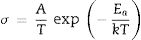
The activation energy of the electrical conductivity of glass-ceramic sealants for SOFCs application is high (∼172kJ/mol), depending on different factors including composition, degree of crystallinity, etc [32].
The estimated activation energy of the samples reported in this study is comparable to the values reported in other researches. The presence of the glass fiber increases the electrical activation energy, which is favorable for glass ceramic seals.
The I–V characteristic curve of the fuel cell tested using the seal synthesized in this study is presented in Fig. 8. The open-circuit voltage (OCV) of the cell was 1.0V at the temperature of 750°C confirming the proper performance of the sealing material. As we used dry hydrogen as a fuel, the theoretical OCV was estimated to be ∼1.0V. It should be, however, noted that the I–V curve of both seals was nearly identical.
–voltage (V) characteristic of GF0 sample.")
The leak rate (LR) was calculated as [43]
where “P” is pressure, “R” is the gas constant, V is the reservoir volume, “T” is temperature, and t stands for the time. Also, “f” and “i” subscripts represent the final and initial states of the system, respectively. The measured normalized leak rate, according to the leak test assembly, for GF0 and GF5 was 1.4×10⁻⁴sccm/cm and 1.7×10⁻⁴sccm/cm, respectively, at 750°C. The calculated leak rates are in an acceptable range for the SOFC application [17].Conclusions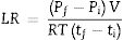
The addition of the short glass fiber to the BCAS glass seal materials hindered the densification process. The presence of glass fibers improved the indentation fracture toughness of the seal material significantly, while reducing the hardness and compressive strength. The CTE of the composite glass seal materials could be well tailored through the control of composition and/or crystallization process. The softening temperature of the seal was increased as the glass fiber was raised, resulting in the development of seals with a higher working temperature. It was concluded that BCAS glass seals with only 5wt.% glass fiber showed improved indentation fracture toughness without any detrimental effect associated with the other mechanical and thermal properties. The composite seals exhibited the proper sealing performance under the SOFC working condition at 750°C. The performance of the composite seals over a long period under fuel cell working conditions requires more investigations.
The authors acknowledge the financial support from Shahrood University of Technology.

