


In this work, alumina-coated YTZP materials are proposed as means to combine the mechanical reliability of YTZP with the stiffness and hardness of alumina. Additionally, compressive stresses are developed in the alumina coating when cooling from the sintering temperature due to the thermal expansion mismatch between alumina and YTZP.
The proposed processing method involves dipping of pre-sintered YTZP specimens in stable alumina suspensions and co-sintering of the dipped specimens. The influence of the processing parameters on the macro and microstructure of the materials has been established. Berkovich indentation has been performed to determine the Young's modulus of the substrates and coatings. The structural integrity of the coatings has been analysed using scratch tests. The Young's modulus. The optimised specimens present high resistance to scratch up to loads of 150N.
En este trabajo, se proponen los materiales YTZP recubiertos de alúmina como instrumento para combinar la fiabilidad mecánica de YTZP, con la rigidez y la dureza de la alúmina. Adicionalmente, con este diseño, el material cerámico se ve reforzado por las tensiones residuales de compresión que aparecen en el recubrimiento de alúmina durante el enfriamiento desde la temperatura de sinterización, debido a la diferencia en coeficientes de expansión térmica entre la alúmina y la YTZP.
El método de procesamiento propuesto implica la inmersión de muestras de YTZP pre-sinterizadas, con un 42% de porosidad abierta, en suspensiones de alúmina estables, y la posterior co-sinterización de los materiales recubiertos.
En este trabajo se ha establecido la influencia de los parámetros de procesamiento en la macro y microestructura de los materiales. Así mismo, se ha determinado el módulo de elasticidad de los sustratos y de los recubrimientos mediante ensayos de nanoindentación con puntas de tipo Berkovich. Finalmente, se ha analizado la integridad estructural de los recubrimientos mediante ensayos de rayado. Los recubrimientos optimizados presentan alta resistencia al rayado bajo cargas de hasta 150N.
Materials constituted by tetragonal zirconia polycrystals doped with 3mol % yttria (YTZP) combine high fracture strength (>1000MPa), fracture toughness (∼5MPam1/2) and high reliability (Weibull modulus>10) at room temperature [1,2]. However, these materials present relatively moderate hardness (HV≈12–13GPa) [2] which may limit their use in some structural applications. Moreover, they present limitations such as environmentally assisted slow crack growth and metastable transformation of the tetragonal phase to the monoclinic phase under wet environments from room temperature up to 400°C. Transformation results in surface roughening and microcracking, which leads to lower wear resistance [2–6]. On the other hand, alumina offers a unique combination of high hardness (HV≈18–20GPa) [2,7], corrosion resistance, thermal stability and high wear resistance [8]. However, it has relatively low fracture toughness (≈2.5–4MPam1/2) and low and variable strength [9].
One approach to solve limitations of both alumina and YTZP ceramics is the development of alumina-zirconia composites to combine the advantageous characteristics of both phases. In particular, zirconia-toughened alumina (ZTA) with low zirconia content as second phase (<15vol%) shows higher fracture toughness and hardness than alumina and YTZP, respectively [2,10–14]. However, YTZP as second phase in ZTA composites is under tension [14], so it is still liable to ageing in contact with wet environments [2,10,13], although significant resistance to ageing may be achieved [2]. Another design strategy, for improving the surface hardness of YTZP materials while avoiding the problem related to phase transformation, is to produce laminated structures designed to induce compressive residual stresses at the surface by combining ceramics with different thermal expansion coefficients. For instance, alumina-YTZP symmetrical laminated structures in which surface alumina layers are subjected to compressive residual stresses show hardness values similar to those of single phase alumina combined with improved apparent surface fracture toughness and fracture strength [15–17]. These laminated structures have a great potential for applications involving wear processes [18].
In a previous work [19], alumina-coated YTZP materials were proposed as means to improve the wear resistance of YTZP. YTZP specimens coated by homogeneous alumina layers of about 250–200μm were obtained by dipping pre-sintered YTZP substrates with open porosity in alumina suspensions and subsequent sintering. The wear resistance of the coated specimens was much higher than that of monolithic YTZP. However, the coatings presented some porosity resulting in Young's modulus (Berkovich nanoindentation: E≈330GPa) and hardness (Vickers Hardness≈16.6GPa; Berkovich nanoindentation: H≈22GPa) [20] lower than those of a reference dense alumina (Berkovich nanoindentation: E=422±10GPa, H=26±1GPa; Vickers Hardness=19.6±0.6GPa) [21,22]. The fact that coating was done only on one face of relatively large thickness specimens was identified as responsible for such poor mechanical performance.
In this work, the processing parameters have been changed focusing coatings with higher density. In order to facilitate the compatibility of shrinkages during sintering and thermal expansion strains on cooling, symmetric specimens have been prepared using thinner discs and suspensions with lower solid contents. As terms of comparison, specimens using the suspension with high solid loading previously used have been processed and characterised.
ExperimentalHigh purity commercial zirconia powders (TZ-3YS, Tosoh, Japan) were isostatically pressed (200MPa) in the shape of cylinders. After a thermal treatment at 1150°C for 2h in air, the cylinders were cut into discs of approximately 10mm in diameter and 4mm in thickness and rectified for surface conditioning. Open porosity of these pre-sintered zirconia discs was approximately 43%.
Suspensions of alumina (Condea, HPA05, USA) were prepared in ethanol to solid loadings of 2, 3, 5 and 10vol% adding 0.5wt. %, on a dry solids basis, of PEI (Polyethylenimine, Mw 2000, Aldrich) as dispersant, and sonicated for 2min (Ultrasonication Probe, UP 400S, Hielscher, Germany). The coatings were deposited on both sides of the YTZP discs, using a lift to dip and withdraw the sample in the alumina suspension. The system is provided with a clam which allows grabbing the disc letting free both sides of the disc and masking edges. The YTZP substrates were dipped and maintained in the alumina suspensions for 20s, after which they were withdrawn at 7mm/s.
After drying in air at room temperature, the coated compacts were sintered at 1280°C during 4h and 1500°C for 2h, using 2°Cmin−1 as heating and cooling rates. Pre-sintering and sintering temperatures were selected from sintering studies to reach full density of reference single-phase monolithic YTZP and alumina compacts while avoiding undesirable grain growth [22]. Final dimensions of the sintered discs were diameter φ≈9.5mm and thickness, t≈3mm.
The three series of specimens corresponding to the three different solids loading in the suspensions (2, 3 and 5vol%) were fabricated in four different batches, named S0, S1, S2 and S3, to investigate reproducibility of the shaping process.
Diamond machined cross sections of the sintered coated specimens were characterised by scanning electron microscopy (Tabletop Microscope TM-1000, Hitachi, Japan) after polishing with diamond past of sizes down to 3μm. The thickness of the coatings was measured directly from the micrographs.
Young Modulus and hardness determinations were carried out in the cross sections. Berkovich nanoindentations of 500nm depth were done (MTS Nanoindenter XP, USA) and the load-penetration depth curves during the tests were recorded. Data were taken in continuous stiffness measurement (CSM) mode, in which a simultaneous oscillating force is applied which is several orders of magnitude lower than the nominal load, allowing measuring the properties in the whole range of penetration. Hardness values and Young's modulus given are those corresponding to maximum penetration depth and they were calculated using the method of Oliver and Pharr [23]. For the zirconia substrates, the results presented are the average of 9 values determined in an arrangement of 3x3 indentations separated 25μm. For each alumina coating, the values reported are the average and standard deviation of 6 randomly located indentations, avoiding defects like pores and grain pullout induced by polishing.
Scratch tests were performed in a CSM Revetest scratch tester (CSM Instruments SA, Switzerland), using a Rockwell indenter (120° diamond cone). The length of each scratch was 5mm, and the load was increased linearly from 0 to 150N. The chipping load was taken from observations of the scratch track in the optical microscope (Olympus LEXT, Japan), identifying the point where chipping started. For each processing condition, reported values are the average of three tests and errors are the standard deviations.
ResultsMicrostructure and mechanical propertiesFig. 1 shows characteristic cross sections of the specimens prepared using the highest solid loading (10vol%). In general, the coatings presented high density and its thickness was around 250μm. However, delamination was observed at the coating-substrate interfaces. Additionally, transverse cracks that even entered the substrates and cracks parallel to the interfaces were found in the coatings (Fig. 1c). These later two kinds of crack were very open and presented non flat faces.

Fig. 2 shows characteristic cross sections of the sintered specimens prepared using solid loadings of 1, 3 and 5vol%, and the measured thickness values are plotted in Fig. 3. Thickness of the coatings was coincident at both sides of the specimens and reproducibility was found for different batches. Thickness increased smoothly with solids loading of the suspension up to 5vol%. From 5 to 10vol% a sharp increase of thickness was found. The associated increase of the dispersion of data reveals the decrease of the reliability of the shaping process.
 Solid loading 1vol% Al2O3. (c–d) Solid loading 3vol% Al2O3. (e–f). Solid loading 5vol% Al2O3.")
Characteristic cross sections of the sintered specimens. Specimens fabricated from suspensions with different solids loadings of Al2O3. Two different batches are compared for each solids loading. Low magnification SEM micrographs of polished sections. (a–b) Solid loading 1vol% Al2O3. (c–d) Solid loading 3vol% Al2O3. (e–f). Solid loading 5vol% Al2O3.

In general, defect free and dense coatings and good joining with the substrate were obtained (Fig. 2). The most frequent defects were material volumes protruding even detached from the coatings as those shown in Fig. 4.
 Protruding volume. Specimen fabricated using a solid loading 1vol% Al2O3. (b) Detached volumes. Specimen fabricated using a solid loading 5vol% Al2O3.")
Young's modulus and hardness of the substrates and the coatings as a function of the solid loading are plotted in Fig. 5. There are no significant differences between the values for substrates. Results for the coatings present higher relative variability (>2×) than for the substrates. Both properties are significantly lower for the coatings prepared with the suspension with the lowest and the largest solid loadings (1 and 10vol%) and similar for 3 and 5vol%. The small increase from 3 to 5vol% stays inside the variability of the results.
 Young")
Properties determined by nanoindentation as a function of the solid loading, SL, of the alumina suspension used to shape the coatings. Data previously obtained for 10vol% solids are plotted for comparison. (a) Young's modulus of the coating, Ec, and the substrate, Es. (b) Hardness of the coating, Hc, and of the substrate, Hs.
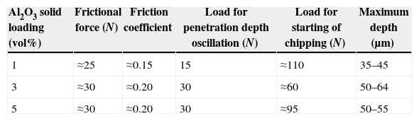
Characteristic results of scratch tests are shown in Fig. 6. Optical microscopy micrographs of the residual scratch tracks and the corresponding plots of the evolution of different quantitative parameters as a function of the increasing normal load are provided. The localisation of the first chipping together with the corresponding value of the normal load is signalled in each micrograph. Typical values of the plotted parameters for the different shaping conditions are summarised in Table 1.
 Solid loading 1vol% Al2O3. (b) Solid loading 3vol% Al2O3. (c) Solid loading 5vol% Al2O3.")
Characteristic results of scratch tests for specimens shaped. Optical microscopy micrograph and COF plots. The central part of the residual groove presents bright contrast and chipping is revealed by the dark zones at the edges of the groove. (a) Solid loading 1vol% Al2O3. (b) Solid loading 3vol% Al2O3. (c) Solid loading 5vol% Al2O3.
Typical values of the quantitative parameters recorded during the scratch tests shown in Fig. 6.
| Al2O3 solid loading (vol%) | Frictional force (N) | Friction coefficient | Load for penetration depth oscillation (N) | Load for starting of chipping (N) | Maximum depth (μm) |
|---|---|---|---|---|---|
| 1 | ≈25 | ≈0.15 | 15 | ≈110 | 35–45 |
| 3 | ≈30 | ≈0.20 | 30 | ≈60 | 50–64 |
| 5 | ≈30 | ≈0.20 | 30 | ≈95 | 50–55 |
In all specimens, scratch grooves could be optically observed from the beginning of the scratch test where the smaller loads were applied. For 1vol% specimens the whole residual groove presented bright contrast and limited lateral cracking was revealed by the dark zones at the edges of the track from loads about 110N (Fig. 6a). Extensive lateral cracking was observed from loads about 60 and 95N for 3 and 5vol% specimens, respectively. In these later cases, the bright contrast eventually disappeared under the extensive lateral cracking (Fig. 6b and c).
The penetration depths increased along the scratch lengths. For 3 and 5vol%, the low-load portions of the penetration depth profiles were smooth, with negligible fluctuations up to loads about 7N where a sudden valley appeared in the profiles (Fig. 6b and c, Table 1). For these specimens, numerous clearly defined valleys appeared for applied loads higher than 30N.
For specimens shaped with 1vol% solid loading (Fig. 6a, Table 1), the penetration depth curves showed defined valleys practically from the beginning of loading and especially from 15N. It has to be remarked that the actual residual depths of the grooves are smaller than the measured maximum penetration depths due to elastic recovery of the material when unloading.
The frictional force is a tangential force induced by the applied normal load and the displacement of the contact between the conical tip and the sample surface when the tip is moving forward. The coefficient of friction (COF) is the ratio of this force to the applied normal load. Both parameters presented typical uncertainties in the low load region, due to the instability of the contact when the conical pointer is beginning to plow into the specimen [24,25]. After this initial transient interval, they increased continuously with the applied force presenting some oscillations until a force of around 30N was reached. Then, the frictional force increased continuously with the applied force and presented small singular peaks and valleys practically through the whole test. Maximum values reached at the end of the test were similar for 3 and 5vol% and higher than those for 1vol%. The COF behaved accordingly and the final COF values were also similar and the highest for 3 and 5vol%.
Fig. 7 shows characteristic scanning electron micrographs of scratch portions about 1.2mm from the end of the scratch track of tested specimens. The characteristics of the damage are revealed by the images obtained in back scattered mode (Fig. 7d–f). All the specimens presented extensive chipping at both sides of the scratch grooves at high loads. For specimens shaped using the lowest solid contents (1 and 3vol%), the zirconia substrates are revealed while for the ones shaped using 5vol% the substrate is practically not detected meaning that chipping took place in the coating without hardly reaching the substrate.
DiscussionMicrostructure and mechanical properties Secondary electrons. (d–f) Back scattered electrons: the white phase is the zirconia substrate. (a and d) Solid loading 1vol% Al2O3. (b and e) Solid loading 3vol% Al2O3. (c and f) Solid loading 5vol% Al2O3.")
Results described above show that it has been possible to process specimens with crack-free alumina coatings using suspensions with 1–5vol% solid loading (Figs. 1–4) whereas extensive cracking appeared for 10vol% suspensions (Fig. 1). The obtained coatings are reproducible in thickness and density for concentrations within the range 1–5vol% of dispersed alumina in ethanol suspension. Thickness increases from values below 80μm for 5vol% suspensions (Figs. 2 and 3) up to 250μm for a 10vol% suspension. Coating growth has not a linear evolution with the concentration of the suspension.
As discussed in the introduction, residual stresses would be expected to develop during cooling from the sintering temperature in the substrate as well as in the coating due to thermal expansion mismatch between YTZP and alumina.
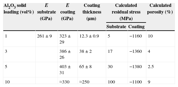
Expected values for residual stresses can be obtained using the simple model of a symmetric laminate the thermal expansion coefficient of alumina, αA, and YTZP, αZ, (average from 25 to 1000°C: αA≈8.2×10⁻⁶K−1 and αZ≈1 0.6×10⁻⁶K−1) [26–28] the experimental Young's modulus of the YTZP substrates and the coatings, and the mean thicknesses for the substrate, ts≈3mm, and the coatings (Table 2, Fig. 5). 1200°C can be selected as limit temperature for accommodation of stresses because no stress relaxation by diffusional creep occurs in fine-grained alumina at temperatures lower than 1200°C [29].
Average values of the parameters used to calculate residual stresses and porosity and calculated residual stress and porosity values.
| Al2O3 solid loading (vol%) | E substrate (GPa) | E coating (GPa) | Coating thickness (μm) | Calculated residual stress (MPa) | Calculated porosity (%) | |
|---|---|---|---|---|---|---|
| Substrate | Coating | |||||
| 1 | 261±9 | 323±29 | 12.3±0.9 | 5 | −1160 | 10 |
| 3 | 386±26 | 38±2 | 17 | −1360 | 4 | |
| 5 | 403±31 | 65±8 | 30 | −1380 | 2.5 | |
| 10 | ≈330 | ≈250 | 100 | −1100 | 9 | |
High compressive stresses will be developed in the coatings while substrates will be subjected to very low tensile stresses (Table 2). In principle, compressive stresses would not lead to cracking of the coatings and the expected tensile stresses are not sufficient to originate cracking of the YTZP substrates. The observed delamination in the specimens with the thickest coatings (Fig. 1) can be attributed to the presence of high shear stresses at the interfaces. The non flat faces of the additional transverse and parallel cracks with large openings reveal that they were probably formed during sintering by a combination of stresses due to thermal expansion and sintering rate mismatches.
Cracks were not observed in the specimens with thinnest coatings (Fig. 2). Even though the necessary condition for delamination should be fulfilled due to the high shear stresses expected at the interfaces, the critical relationship to produce cracking between thickness and residual stresses proposed by Evans [29] is not reached in the thinner coatings.
Young's modulus, E, and hardness, H, of the substrates were of the same level as those determined for dense YTZP materials by nanoindentation (E=246±12GPa, H=16.9±0.9GPa [24].
E and H values for the coating shaped from the lowest solid content suspension were the lowest and similar to those previously obtained for non-optimised coatings discussed in the introduction [20]. Both properties were higher and similar for 3 and 5vol% These later values were slightly lower than those obtained using the same experimental procedure for the reference alumina with 99% of theoretical density (E≈422GPa, H≈26GPa) [21].
The differences between the values of E and H of the coatings and those of the reference alumina should be related to the higher porosity of the former. Even though it has been reported that tensile residual stresses can affect the measured E and H[30,31], this effect should necessarily be very small for the coatings studied here due to the absence of pile up, as observed in other ceramics [32]. Porosity, P, in the coatings can be evaluated from the experimental Young's modulus values using the well known exponential relation between porosity and Young's modulus:E=E0exp(−bP)with E0 the Young's of the fully dense material, b, a parameter which depends on the spatial configuration of the pores assembly and the material, and P, the volume fraction of porosity.
This relationship was originally obtained empirically and derived latter from MSA (Minimum Solid Area) models. These MSA models were proved to be valid up to levels of porosity of more than 20% in the case of spherical pores in cubic stacking [33,34].
From the Young's modulus value obtained for the reference alumina using the same experimental method ([21], 422GPa) and its porosity (1%) and the value b=3 determined for alumina with spherical pores [35,36] it can be inferred the Young's modulus for the totally dense alumina, E0≈435GPa. From the same relationship and the experimental E values, the porosity of the coatings fabricated using the lowest solid content should be the highest and decrease for 3 and 5vol% (Table 2).
Summarising, increasing solid content in the suspension used to shape the coatings leads to increasing coating density. The sharpest increase occurs when the solid content increases from 1 to 3vol%, further raise of the solid content level to 5vol% leads to slight density improvements. Moreover, a decrease of the density and cracking of the coatings occur when more concentrated suspensions (10vol%) are used. Young's modulus and hardness increase with increasing density of the coatings.
Scratch testsInduced scratch damage is a complicate phenomenon that includes a combination of processes, elastic and plastic deformation and brittle fracture. Grain dislodgement, microcracks, radial cracks and lateral cracks with associated chipping contribute to brittle fracture damage. Due to the limited slip systems in ceramics, the main deformation mechanism is brittle fracture, leading to the formation of chips along the scratch grooves, as it has been reported for bulk alumina [24,25,37]. Plastic deformation in alumina is limited to the initial stages of the process. The behaviour of YTZP under scratch is different from that typical of ceramics as extensive plastic deformation and phase transformation might occur under localised loads [38,39].
For the three alumina coatings studied in the present work, the characteristic features of the scratch grooves and the dependence of the quantitative parameters with increasing loads are similar to those reported for different bulk alumina materials [24,25,37]. An increasing residual scratch groove width with load is observed in all tests. The central part of the groove is plastically deformed and surrounded by brittle damage whose extension depends on the scratch load. Brittle damage is often associated to lateral cracking and chipping.
Alumina deformation can be purely elastic-plastic at the initiation of the process, which gives smooth penetration depth profiles for low depths. The appearance of a sudden valley in the profiles indicates the presence of brittle fracture. Further brittle damage is revealed by the irregular oscillation of the profile under continuously increasing load. Fluctuations are also observed in the frictional force, which increases with the applied load. Oscillations in the penetration depth and force profiles reflect the intermittent nature of material removal during scratching. Large fluctuations usually reflect the removal of large chips [37].
For the lowest density coating (1vol%, Fig. 6a, Table 1) brittle damage revealed by valleys in the penetration occurred from the beginning of the tests. It was more significant from lower loads than for the denser coatings. Maximum penetration depth was the lowest and the load for chipping was the highest. The zirconia substrate could be observed in some zones (Fig. 7a and d) indicating total detachment of the coating.
Brittle damage in the high density coatings (3 and 5vol%, Fig. 6b and c, Table 1) started at higher loads and initially the severity of the damage, measured by the penetration depth, remained of the same order as for the low density coating. However, severe chipping occurred for higher loads, especially for the 5vol%, for which the zirconia substrate was clearly revealed (Fig. 7b and e).
The above discussed observations can be related to scratch damage processes described as follows. In the low density coating, sinking of the porous material under the localised stresses as well as fracture initiation from pores subjected to the shear stresses originated by the tangential loads occurred from the beginning. Both processes can take place from relatively low loads and will originate material detachment from the coating. As load increases, the depth of the groove increases reaching values of the order of the coating thickness (≈12μm, Fig. 5). At this point the YTZP substrate is in direct contact with the indenter and will experience plastic deformation which accommodation would require lateral cracking (Figs. 6 and 7a and d).
The highest density coatings fabricated from suspensions with 3 and 5vol% solid loading (porosities=4 and 2.5vol%, Table 2) did not experience sinking under the applied loads and their resistance to tangential stresses was higher. Consequently, the specimens presented relatively small maximum penetration depths (≈50–64μm, Table 1) which for the densest material (5vol%) were even smaller than the coating widths (≈60–65μm). Extensive chipping in these cases comes from deformation of the coatings and not of the substrates (Figs. 6b, c and 7b, f). For the coatings with the lowest porosity (2.5%, Table 1), substrates remained coated after testing.
ConclusionsIt is possible to obtain reliable alumina coatings on zirconia specimens by dipping porous zirconia specimens into stable alumina suspensions in such a way that a symmetric tri-layer structure is obtained.
Optimum processing can be manipulated in terms of the solid content of the alumina suspension which determines the density of the coating.The optimised specimens present high resistance to scratch up to loads of 150N.
The authors acknowledge the support of the projects MAT2013-48426-C2-1-R MAT2012-38650-C02 and MULTIMAT-CHALLENGE, Ref: S2013/MIT-2862.

