


This study mainly investigated the effects of silicate concentration at the range of (16g/L to 56g/L) on the plasma electrolytic oxidation of Zircaloy-2 in potassium hydroxide/sodium silicate electrolytes in detail, including the growth behavior, wear and corrosion resistance of as-obtained ZrO2/SiO2 alloyed coatings. It was found that the coating thickness increased continuously on increasing the silicate concentration in electrolyte. Besides, the amount of t-ZrO2 in the coatings increased with increase of silicate concentration in electrolyte, while the amount of m-ZrO2 decreased. Comparative studies have shown that the coatings formed in electrolyte with high silicate concentration possessed superior wear and corrosion performance, which could be ascribed to heavy silica deposition associated with the presence of t-ZrO2 stabilized by SiO2. The results may provide guidance for obtaining high performance of ZrO2/SiO2 alloyed coatings. Besides, it is believed that the presence of Si species in zirconia endows the coatings with enhanced bioactivity like bioactive glasses and ceramics coatings and we envision that the as-prepared ZrO2/SiO2 alloyed coatings have great potential for biological applications.
Este estudio investigó en detalle los efectos de la concentración de silicato en el rango de (16 a 56g/l), en la oxidación electrolítica por plasma de Zircaloy-2 en electrolitos de hidróxido de potasio/silicato de sodio, incluido el modo de crecimiento y la resistencia al desgaste y a la corrosión de los recubrimientos de aleaciones de ZrO2/SiO2 obtenidos. Se descubrió que el espesor del recubrimiento aumentaba continuamente al aumentar la concentración de silicato en el electrolito. Además, la cantidad de t-ZrO2 en los recubrimientos aumentó con el aumento de la concentración de silicato en el electrolito, mientras que el contenido de m-ZrO2 disminuía. Estudios comparativos han demostrado que los recubrimientos formados en electrolito con alta concentración de silicato poseían mayor resistencia al desgaste y a la corrosión, que podría atribuirse a una fuerte deposición de sílice asociada con la presencia de t-ZrO2 estabilizado por SiO2. Los resultados pueden proporcionar guía para obtener un alto rendimiento de los recubrimientos con aleaciones ZrO2/SiO2. Además, se cree que la presencia de especies de Si en la circona dota a los recubrimientos con una bioactividad mejorada como recubrimientos cerámicos o vítreos bioactivos, y prevemos que los recubrimientos de aleaciones ZrO2/SiO2 preparados tienen un gran potencial para aplicaciones biológicas.
Surface treatment is a well-adopted method for preparation of advanced functional materials [1–8]. Recently, plasma electrolytic oxidation (PEO) as an effective surface treatment process has attracted much attention by scientists working in the fields of surface engineering and corrosion protection [9–12]. This technique evolved from conventional anodizing, but demands much higher working voltages to generate plasma discharge on the surface of treated work pieces. Under the high temperature of the plasma discharge, the functional ceramic coatings will be sintered and formed on the surface of the so-called valve metals (Mg, Al, Ti, Zr, etc.) or their alloys [13–18]. The technique is largely electrochemical in nature, however, plasma-enhanced physico-chemical processes are also known to participate concurrently in the coating formation process.
Zirconium alloys are commonly used as structural materials for water-cooled nuclear power reactors, where they are subjected to severe environmental conditions. Corrosion and wear are the main factors leading to the degradation of such materials [19–24]. Recently, many studies have shown that PEO treatments can be a feasible way to improve the corrosion resistance and wear resistance of these alloys [25–27]. More importantly, due to their excellent biocompatibility, high mechanical strength and fracture toughness, reasonably good corrosion resistance, low thermal conductivity, together with low elastic modulus (92GPa) and low magnetic susceptibility [28–31], zirconium alloys are also seen as potential biomaterials. However, appropriate surface treatment is also required in such cases since the native oxide (ZrO2) film on the alloys is bio-inert [28,32] and the formation of chemical bonds with bone tissue is difficult during implantation, which could be a drawback because an early integration between biomaterial and bone is advantageous for most implant applications [33].
Silicate-based electrolytes are widely used in the PEO of valve metals [11,12,14,34], and they also have been used for the treatment of zirconium and its alloys recently [25–27]. The use of silicate electrolytes can incorporate a large amount of Si species into the obtained coatings, which is an efficient way to enhance the biocompatibility of the underlying metals. Silicon (Si) is known to be an essential element for the normal growth and development of bone and connective tissues [35–37]. In recent years, an increasing number of evidence has supported the hypothesis that the presence of Si can contribute to the enhanced bioactivity of some bioactive glasses or ceramics, and significantly increase the up-regulation of osteoblast proliferation and gene expression [38].
PEO coatings on zirconium alloys are mainly consisted of zirconium oxide, which, as a promising engineering material, is known for its good chemical and thermal stability, wear resistance and mechanical strength [39]. The performances of the coatings are strongly correlated with the phase composition of present zirconia, which could be significantly determined by the processing conditions of PEO such as the electrolyte composition, electrical regime and so on. Among the various electrolytes that are suitable for PEO, silicate-, aluminate- and phosphate-based ones had been widely used. Cheng et al. [40,41] studied the phase compositions and microstructures of PEO coatings formed on zirconium alloys in an silicate-based electrolyte, and found that the wear resistance of the coatings was significantly improved because the silicon species that were incorporated into the coating had caused the stabilization of tetragonal zirconia (t-ZrO2). Although a few researches about investigating the effect of electrolyte composition on PEO process have been reported, a high concentration of electrolyte, especially for Na2SiO3, is still rarely applied for PEO studies. In addition, studies on the content of Si in PEO coatings also play an important role in the preparation of biocompatible coatings. Finally, it was also reported that the use of a high concentration of aluminate electrolyte can benefited the wear resistance of the resultant PEO coatings significantly [42–44,40]. In this paper, the PEO behaviors of Zircaloy-2 in potassium hydroxide/sodium silicate electrolytes were investigated. The effects of silicate content in electrolytes on the wear and corrosion properties of the resultant coatings were compared for the first time, and our research may provide guidance for obtaining high performance of ZrO2/SiO2 alloyed coatings.
ExperimentalZircaloy-2 alloy was cut into the shape of rolled plate, and then mounted in resin to prepare specimens with a working area of 20mm×10mm. The experimental setup was same as the one described in our previous paper [30]. The compositions of the electrolytes were 1g/L KOH+c g/L Na2SiO3·9H2O (c=16, 32, 48 or 56). The electrical regime was a pulsed bipolar waveform, using a duty cycle of 20% at 1000Hz [30], with the positive and negative current densities kept at 150 and 100mA/cm2 (rms), respectively.
The thicknesses of the coatings were determined by an eddy current thickness gauge (TT260, Time Group, Beijing). The surfaces and cross-sections of the PEO coatings were characterized by scanning electron microscopy (SEM, QUANTA 2000, FEI, USA, or a JEOL JSM6700F Instrument), and the elemental composition was analyzed by energy-dispersive X-ray spectroscopy (EDS). Phase compositions of the coatings were examined by using a Rigaku D/MAX 2500 X-ray diffractometer (Cu-Kα radiation).
The tribological performance of the PEO coatings was evaluated using a CETR UMT-3 tribometer. The test method utilized a Cr steel ball (diameter 9.5mm, hardness 62 HRC) that slides against a flat PEO-treated specimen in a linear, reciprocating motion. A load of 20N or 30N was applied, with a stroke length of 7.5mm and frequency of oscillation of 5Hz.
Electrochemical behaviors of the samples were evaluated by potentiodynamic polarization curve measurements using a CHI660C electrochemical workstation in 3.5wt% NaCl solution. The electrochemical tests were carried out at room temperature in a conventional three-electrode cell with a test area of 20mm×10mm, in which the samples were used as the working electrode, a platinum electrode as the counter electrode and a saturated calomel electrode as the reference electrode. Before the electrochemical analysis, the samples were kept in the solution for 1h to stabilize the open circuit potential (OCP). The voltage applied in the potentiodynamic polarization test was varied in the range of −1.2V to 3V at a scanning rate of 1mV/s.
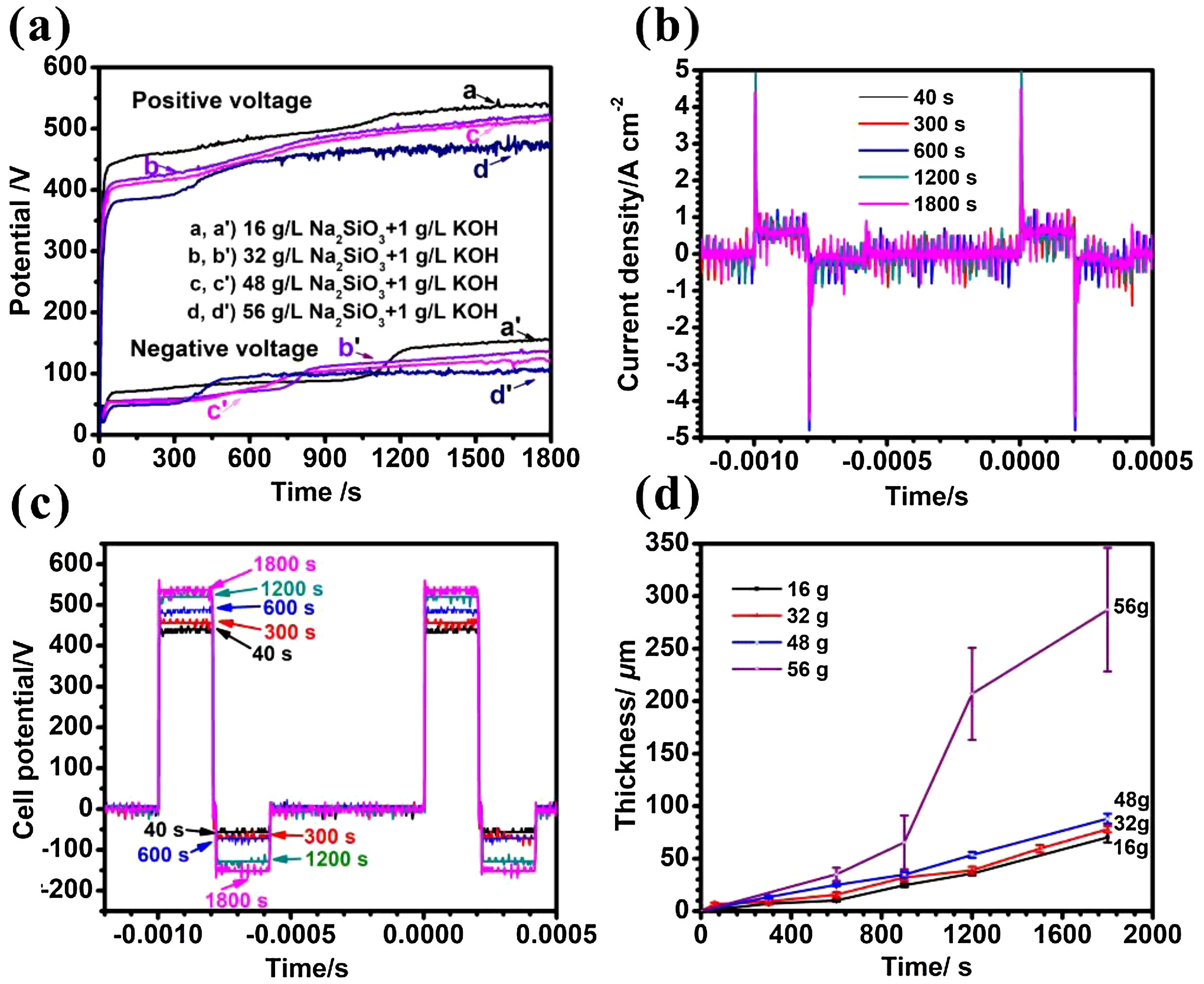
Results and discussionCell potential responses and kinetics of coating growthThe cell potential-time curves during the PEO treatment in the electrolytes with different silicate concentrations are presented in Fig. 1(a). As is shown in the picture, all positive potentials showed a similar rapidly rising trend before reaching up to breakdown potential, after which the increase rates were slowing down. The inflection point in voltage-time response is usually called breakdown point, at which the potential is defined as breakdown potential because plasma sparks could be observed obviously at this stage. It can also be seen that the breakdown potential increased from 310, 357, 379–418V with the increase of electrolyte concentration (16, 32, 48 and 56g/L), respectively. This is due to the fact that the breaking down potential is closely related to the specific resistance of electrolyte; specifically, an electrolyte with higher concentration usually has lower specific resistance, resulting in a lower breakdown potential. Depicted in Fig. 1(b, c) are the current and potential waveforms of PEO in electrolyte of 16g/L Na2SiO3·9H2O+1g/L KOH. As shown in Fig. 1(b), the current waveforms at different stages of PEO remained almost constant, which means the output of the power source is quite stable. Also, the potential of PEO increased gradually because the film thickness, and thus impedance, increased with time, as shown in Fig. 1(c). In addition, the relationship between coating thickness and time is shown in Fig. 1(d). It is obvious that the coating thickness increased almost linearly along with PEO processing time. After PEO treated for 30min, the coating thickness reached 70.2μm, 78.8μm, 88.3μm and 289.6μm, and the average increasing rate is 2.3μm/min, 2.6μm/min, 2.9μm/min and 9.7μm/min under different Na2SiO3·9H2O concentration of 16, 32, 48 and 56g/L respectively. One possible reason for this phenomenon may be that more substance would participate in the coating formation process at a higher concentration of electrolyte, resulting in a higher coating growth rate. After treated for 30min, the number of sparks shrank while they became more intense and tended to stay at a fixed point longer, giving rise to a higher standard deviation and a rougher surface.
 Positive and negative (absolute value) peak cell potential-time responses for the PEO of Zircaloy-2 alloy of different concentrated silicate electrolytes, (b) current and (c) voltage waveforms during PEO of Zircaloy-2 at different times in 16g/L Na2SiO3+1g/L KOH, (d) dependence of coating thickness on time of PEO for Zircaloy-2 in the different electrolytes. Error bars represent the standard deviations.")
(a) Positive and negative (absolute value) peak cell potential-time responses for the PEO of Zircaloy-2 alloy of different concentrated silicate electrolytes, (b) current and (c) voltage waveforms during PEO of Zircaloy-2 at different times in 16g/L Na2SiO3+1g/L KOH, (d) dependence of coating thickness on time of PEO for Zircaloy-2 in the different electrolytes. Error bars represent the standard deviations.
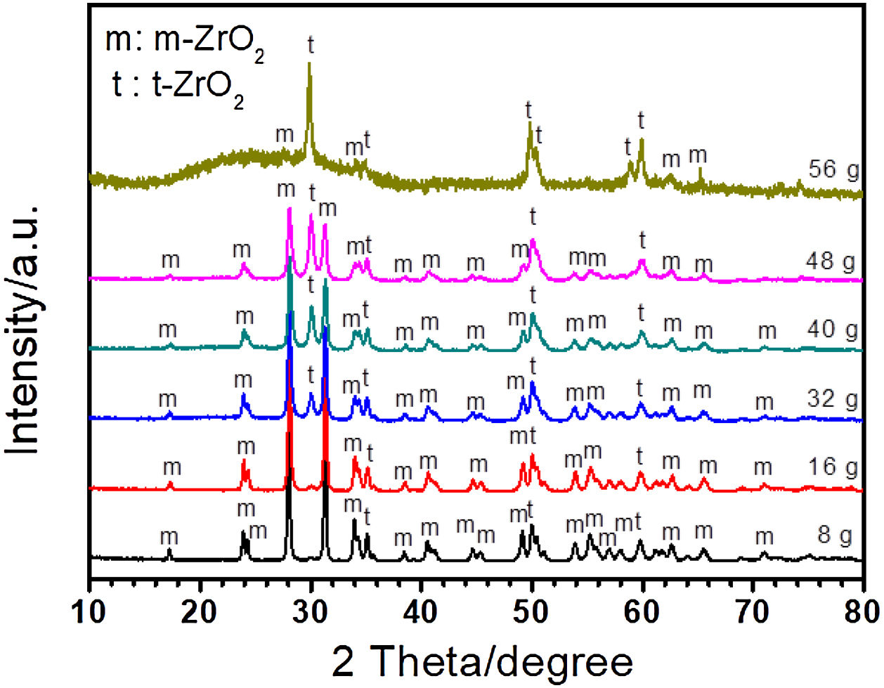
ZrO2 is the main composition of coating formed on Zircaloy-2 alloy by PEO treatment. There are three types of ZrO2 at different temperature, i.e., monoclinic (m-ZrO2), tetragonal (t-ZrO2), and cubic phase (c-ZrO2). Among them, m-ZrO2 is a stable phase at room temperature, and t-ZrO2 is also stable but usually formed at high temperature [45]. During PEO process, the substrate and oxide are melted due to the high temperature generated by plasma sparks, and different kinds of ZrO2 phases are formed at different stage. Fig. 2 shows the XRD results of coatings formed in different concentrations of silicate electrolyte after 30minutes’ PEO treatment. As presented in Fig. 2, the amount of t-ZrO2 in the coatings increased with increase of silicate concentration in the electrolyte, while the amount of m-ZrO2 decreased. This could be attributed to the fact that in higher concentration of silicate electrolyte more Si species, which are usually considered to be effective for the stabilization of t-ZrO2, had incorporated in the resultant coatings, and thus leading to a larger amount of t-ZrO2[46–50]. With the increase of Si content, more t-ZrO2 would be formed in the coating, which is indicated by the weak diffraction peak of m-ZrO2 and the dominant peak of t-ZrO2 in the coating formed in 56g/L Na2SiO3+lg/L KOH electrolyte. It should be noted that a weak amorphous peak was also detected. Based on the EDS analysis, the amorphous should mainly be SiO2, which is quite usual in PEO coatings formed in Si-containing electrolyte because of the good glass forming ability of the element Si. Further, the amorphous phase in PEO coatings is usually considered to exist in an extremely thin amorphous layer at the interface between coating and substrate and in the wall of the large inner pores inside the PEO coatings because of the quenching effect there [51–54,12,55–58].
Morphologies of the coatings.")
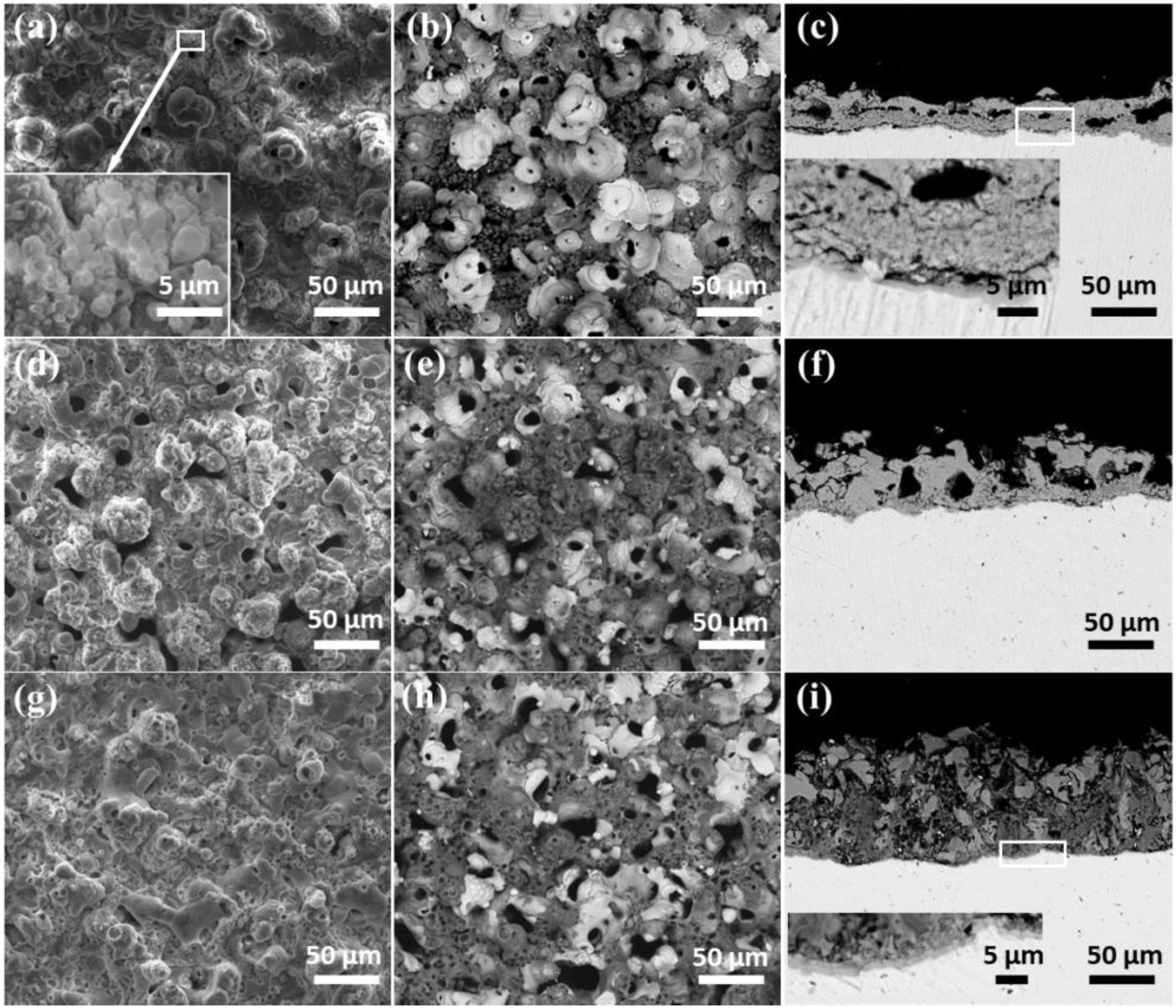
Fig. 3 shows the surface and cross-sectional morphologies of coatings formed after PEO treated for 30min in electrolyte with different concentrations of silicate. The SEM images of the coating formed in electrolyte with 16g/L Na2SiO3·9H2O were shown in Fig. 3(a–c). As shown, the micro pores and pancake structures could be clearly observed. In addition, the stacked layered structure also exists in the coating, as indicated in the inset. This typical structure might be formed under the deposition of silicate which comes from the electrolyte. Notably, a white flower-like structure could be seen in Fig. 3(b), which displays a solidification structure and is a typical feature of the coatings formed in silicate-containing electrolyte on zirconium alloy; however, such structures are not encountered generally in PEO coatings because their formation requires the existence of relatively long-lived melt pools caused by persistent sparks [41]. As indicated in the cross-sectional images (Fig. 3(c)), the coating is consisted of a dense barrier layer which is close to the substrate and a porous outer layer. When increasing the concentration of Na2SiO3·9H2O to 32g/L, the surface and cross-sectional of the coating shows similar morphologies, as shown in Fig. 3(d–f). Interestingly, the amount of white typical structures is less than that of coating formed in electrolyte with 16g/L Na2SiO3·9H2O. Further increasing the silicate concentration to 48g/L Na2SiO3·9H2O, the Fig. 3(g–i) indicate that the surface morphologies are still similar to the above two cases. Nevertheless, there are less micro pores in the coating, as shown in the cross sectional images (Fig. 3(i)). Based on the results above, it is reasonable to conclude that with the increase of silicate concentration in the electrolyte, more silicate would take part in the coating formation process and then co-deposit with the ZrO2, resulting in the formation of a dense layer which is rich in ZrO2 and SiO2.
 and backscattered (b–c, e–f, h–i) electron images; (a, b and c) 16g/L Na2SiO3·9H2O+1g/L KOH, (d, e and f) 32g/L Na2SiO3·9H2O+1g/L KOH, (g, h and i) 48g/L Na2SiO3·9H2O+1g/L KOH.")
Surface and cross-sectional morphologies of the coatings formed for 1800s in the different concentration of silicate electrolyte: secondary (a, d, g) and backscattered (b–c, e–f, h–i) electron images; (a, b and c) 16g/L Na2SiO3·9H2O+1g/L KOH, (d, e and f) 32g/L Na2SiO3·9H2O+1g/L KOH, (g, h and i) 48g/L Na2SiO3·9H2O+1g/L KOH.
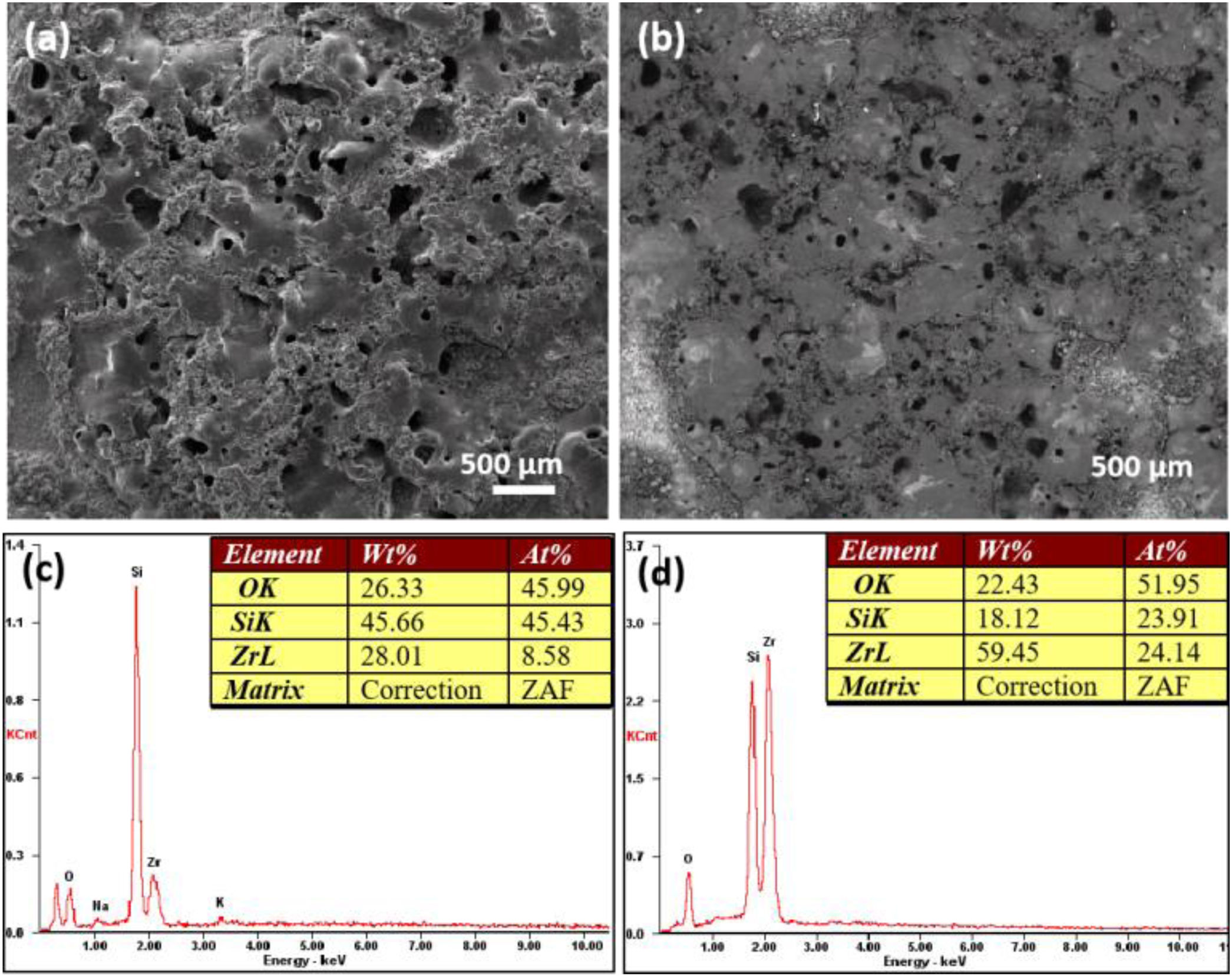
In order to verify the conclusion that the deposition of silicate increased with increase of electrolyte concentration, the images of coating formed after 30min treatment in 56g/L Na2SiO3·9H2O electrolyte are showed in Fig. 4(a, b). Fig. 4(a) was obtained under the secondary electron mode and Fig. 4(b) was obtained under the backscattered mode. In addition, Fig. 4(c, d) are EDS analysis results of coatings formed in 56g/L Na2SiO3·9H2O+1g/L KOH electrolyte and 48g/L Na2SiO3·9H2O+1g/L KOH electrolyte, respectively. In Fig. 4(a), the surface of as-formed coating is quite rough, containing a number of humps. The rough surface area is deeper in color in the backscattered mode (Fig. 4(b)), which might be attributed to a higher deposition of silicon oxide. EDS analysis (Fig. 4(c, d)) indicated that the when increasing the concentration of Na2SiO3·9H2O from 48 to 56g/L, the Si content would increase significantly, which is indicative of the deposition of more silicate. To conclude, the increase of concentration of silicate in the electrolyte could lead to the increasing deposition of silicon oxide in the coating, thus hindering the formation of micro cracks and pores, and finally generating a denser coating.
Dry sliding wear behavior of the coatings formed in silicate electrolyte morphologies of a coating formed for 1800s in the 56g/L Na2SiO3·9H2O+1g/L KOH electrolyte; (c) and (d) are EDS analysis of coatings formed in 56g/L Na2SiO39H2O+1g/L KOH electrolyte and 48g/L Na2SiO3·9H2O+1g/L KOH electrolyte, respectively.")
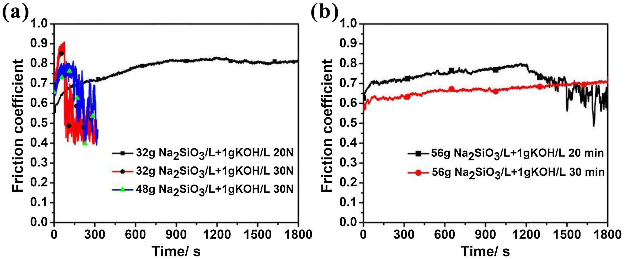
Fig. 5(a) illustrates the relationship between the friction coefficient and friction time obtained by dry slide friction test of the coating after 30min formed in electrolyte with 32g/L Na2SiO3+lg/L KOH and 48g/L Na2SiO3+lg/L KOH (the applied force is 20 or 30N). For the curve corresponded to 32g/L Na2SiO3+lg/L KOH under 20N, at the beginning of the test, the friction coefficient increased quickly, shifting from 0.56 to 0.68 at first 100s. This might be attributed to the rough surface of the coating, in which the protuberance is easy to be worn down by the steel ball, resulting in a quick change of friction coefficient. During 100–600s, the friction coefficient increased slightly from 0.68 to 0.79 and then kept constant at 0.79, which suggests that the transferring layer has been formed and the wear depth has reached the ultimate value. At this stage, only by increasing the load lead to the formation of a deeper wear scar. As for the curve corresponded to 32g/L Na2SiO3+lg/L KOH under 30N, the friction coefficient increased quickly from 0.7 to 0.9 at the first 73s, after which it dropped suddenly to 0.5, revealing that the coating has been worn out, then the coefficient stayed between 0.4 and 0.56. By contrast, regarding the coating formed in electrolyte with 48g/L Na2SiO3+lg/L KOH for 30min, under a load of 30N the friction coefficient initially increased from 0.67 to 0.78 in the first 156s, then it dropped to 0.57, and finally fluctuates between 0.57 and 0.67 till the end of the test. Based on Fig. 1(d), the difference of coating thicknesses under 30min treatment is slight, being 70 and 78μm respectively; however, the former only lasted for 73s before worn out, while the later was worn out until 156s later under a load of 30N. From Fig. 2, it is obvious that former coating has a lower amount of t-ZrO2. Thus, the reason why the coating formed in the later (32g/L Na2SiO3+lg/L KOH) shows a better wear resistance can be reasonably attributed to its higher content of t-ZrO2 than the former (32g/L Na2SiO3+lg/L KOH).
 Coefficient of friction as a function of sliding time under an applied load of 20N or 30N after the corresponding dry sliding tests for a coating formed for 30min in 32g/L Na2SiO3·9H2O+1g/L KOH and 48g/L Na2SiO3·9H2O+1g/L KOH; (b) Coefficient of friction as a function of sliding time under an applied load of 30N after the corresponding dry sliding tests for a coating formed for 20min or 30min in 56g/L Na2SiO3·9H2O+1g/L KOH.")
(a) Coefficient of friction as a function of sliding time under an applied load of 20N or 30N after the corresponding dry sliding tests for a coating formed for 30min in 32g/L Na2SiO3·9H2O+1g/L KOH and 48g/L Na2SiO3·9H2O+1g/L KOH; (b) Coefficient of friction as a function of sliding time under an applied load of 30N after the corresponding dry sliding tests for a coating formed for 20min or 30min in 56g/L Na2SiO3·9H2O+1g/L KOH.
Fig. 5 (b) shows the relationship between the friction coefficient and friction time obtained by dry slide friction test for coating formed in 56g/L Na2SiO3+lg/L KOH for 20min and 30min (the applied force is 30N). It can be seen that the friction coefficient of the coating formed for 30min fluctuated between 0.55 and 0.7 till the end of the test, and the coating was not worn out. In contrast, the wear resistance of the coating formed for 20min is weaker than the former with worn out under slide drying 20min.
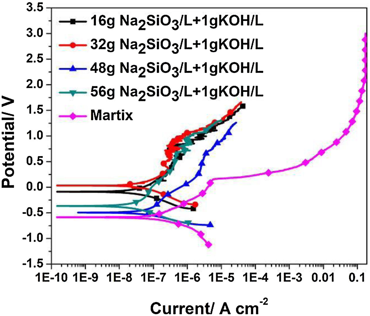
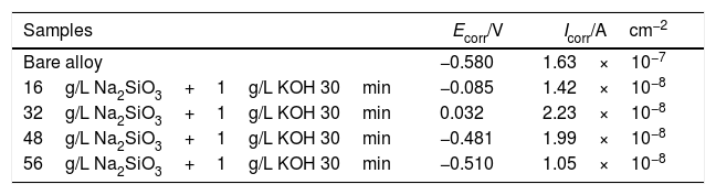
Electrochemical testsFig. 6 shows the potentiodynamic curves of coatings formed for 30min in electrolyte of different silicate concentration, the relating polarization data derived from polarization curves is summarized in Table 1. Because of their excellent corrosion resistance, zirconium and its alloys only corrode and dissolve in certain strong acids such as HF. Therefore, the passivation reaction occurs first in the corrosive medium, and the specific reactions are as follows:

Polarization data derived from polarization curves (Fig. 5).
| Samples | Ecorr/V | Icorr/Acm−2 |
|---|---|---|
| Bare alloy | −0.580 | 1.63×10⁻⁷ |
| 16g/L Na2SiO3+1g/L KOH 30min | −0.085 | 1.42×10⁻⁸ |
| 32g/L Na2SiO3+1g/L KOH 30min | 0.032 | 2.23×10⁻⁸ |
| 48g/L Na2SiO3+1g/L KOH 30min | −0.481 | 1.99×10⁻⁸ |
| 56g/L Na2SiO3+1g/L KOH 30min | −0.510 | 1.05×10⁻⁸ |
After the oxide film is formed, zirconium alloy can be effectively protected. Subsequently, pitting corrosion occurs, and the passivation film is gradually destroyed. As shown in Fig. 5(c), the pitting corrosion of the bare alloy begins at 0.16V, while the potential of pitting corrosion for the PEO treated samples increased positively (∼1.09V). All the corrosion current (Icorr) are almost lowered by one order of magnitude compared to the one of the bare alloy. Among all the samples, the PEO coating formed in electrolyte of 56g/L Na2SiO3+lg/L KOH has the lowest corrosion current (Icorr), which means the best corrosion resistance. The reason may be attributed to the fact that the coating formed in this electrolyte has less micro cracks and a larger thickness which hinders the penetration of corrosive media into the barrier layer. For the coating formed in electrolyte with 32g/L Na2SiO3+lg/L KOH, since it contains obvious cracks in the coating, corrosive media could easily pass through the outer layer and reach the barrier layer. Also, corrosion processes of coatings formed under other conditions almost have the same process. Based on the above results, it is the coating formed in 56g/L Na2SiO3+lg/L KOH that has the best corrosion resistance.
ConclusionsIn conclusion, we provided a study of plasma electrolytic oxidation of Zircaloy-2 in potassium hydroxide/sodium silicate electrolytes. The effect of the silicate content on the growth behavior, wear and corrosion resistance of resultant coatings were systematically revealed. It was demonstrated that the coating thickness increases continuously on increasing the silicate content in electrolyte. Besides, increasing the silicate content in electrolyte can promote the formation of t-ZrO2 in the coatings, and thus resulted in the formed ZrO2/SiO2 alloyed coatings with enhanced wear resistance. Differently, the corrosion resistance of the resultant coatings was not positively correlated with the silicate concentration. The coatings formed in the electrolyte with Na2SiO3 concentration at 56g/L exhibited the best corrosion resistance depending on their relatively dense structure and less of cracks. Our results provided guidance for obtaining high performance of ZrO2/SiO2 alloyed coatings, which have great potential biological applications.
Conflicts of interestThe authors declared no competing financial interest.
The financial support by National Natural Science Foundation of China (51874129), the Natural Science Foundation of Hunan Province (2019JJ60049) and the Scientific Research Foundation of Hunan Provincial Education Department (19B153 and 19B158) is greatly acknowledged.

