


For maximum anchorage in orthodontics, mini-implants have been used for various tooth movements without causing unwanted reactive forces on the teeth. The purpose of this study was to evaluate the mechanical resistance to traction of mini-implants to be evicted from bone and assess whether they can increase their tensile strength depending on its insertion angle (60 and 90°). Pig hip cuts were used for the placement of 5 mini-implants which were inserted with a 60° angulation and a 90° angulation. Ten new 2.5mm (neck)×1.6 (diameter)×8mm (length) with flat head self- drilling mini-implants were used (MOSAS Dewimed. Germany). They were subjected to perpendicular tensile forces, using a universal mechanical testing machine (Instron) with a loading rate of 1mm/min. The results were analyzed using Student's t test. It was observed that 90o angulation mini-implants had better resistance (7.40±2.68 Mpa) than 60° angulation ones (4.21±0.58 Mpa). 90° angulation mini-implants could be a better option for orthodontic treatment due to their higher resistance to traction forces thus improving stability.
Para obtener un anclaje máximo en ortodoncia, se cuenta con el uso de miniimplantes para realizar distintos movimientos dentales sin que se produzcan fuerzas reactivas no deseadas en los dientes. El objetivo de este estudio fue valorar la resistencia mecánica a fuerzas de tracción de los miniimplantes al ser desalojados del hueso, así como evaluar si éstos pueden aumentar su resistencia a la tracción dependiendo del ángulo de inserción (60 y 90o). Se utilizaron cortes de cadera de cerdo, en los cuales se insertaron 5 miniimplantes con angulación de 60° y 5 con angulación de 90°. Se utilizaron 10 miniimplantes autorroscables nuevos de 2.5mm (cuello)×1.6 (diámetro)×8mm (longitud) con cabeza plana marca Dewimed MOSAS, Germany. Se sometieron a fuerzas de tracción perpendiculares a éstos, usando una máquina universal de pruebas mecánicas (Instron) con una velocidad de carga de 1mm/min. Después de realizar el análisis estadístico por medio de t de Student, se observó que los miniimplantes colocados con angulación de 90° y perpendiculares a la cortical, soportaron mayor resistencia (7.40±2.68 MPa) que los miniimplantes a 60° (4.21±0.58 MPa). Podrían ser los miniimplantes colocados a 90° una mejor opción en los tratamientos de ortodoncia por su mayor resistencia a las fuerzas y, por lo tanto, mejorar la estabilidad.
The need of anchorage in orthodontics occurs when teeth natural movements are produced in larger proportions; they must be secured against an anchor which, if possible, should be fixed.1–3 With each application of a dental force, reactive forces will be produced which cause, according to the Third Law of Newton, tooth movements in an opposite direction that in most cases, are unwanted.4 Anchorage can be defined as the resistance that a body presents to be displaced;1in orthodontic terms, the body represents the tooth and the displacement is performed by means of forces which can be light and continuous or heavy and intermittent.5
In orthodontics there are three types of anchorage: minimal, moderate and maximum or absolute. The latter is one of the most widely used, because thanks to it, a minimum of space is lost from an extraction performed to get the space that dental crowding demands.6
Therefore, alternatives have been sought in relation to absolute anchorage where a minimum cooperation from the patient is required, but above all, that the presence of other teeth as anchorage is not required. That is how implants of mini-screw or mini-implants emerged, to be used as maximum anchorage and meet the above mentioned requirements.3
Mini-implants were introduced in orthodontics in 1945, as mentioned by Papadapolus,1 by placing screws of vitallium in the ascending ramus of the mandible of dogs. From then on, they have been used as temporary anchorage for:
- •
Canine retraction.
- •
Retraction of the anterior segment.
- •
Dental Intrusion.
- •
Distalization.
- •
Mesialization.7
The success of mini-implants depends on several factors that directly influence their stability,8 such as:
- •
Cortical bone (quantity and quality).
- •
Type of implant (diameter, length and shape).
- •
Implant position (angle).
- •
Gingival tissue around the implant.
- •
Age of the patient (the amount and quality of bone increases with age).7
- •
Force applied (clinical reports suggest that miniimplants are stable with forces of 50 g (0.5 N) to 450 g (4.5 N).7–9
This study aimed to assess the amount of traction force that mini-implants can withstand placed in bone with two different angulations until its eviction or fracture. In the present study, we chose angulations of 60 and 90o for comparison and to observe which presented the greatest resistance to tensile forces.
Materials and methods10 new 2.5mm (neck)×1.6 (diameter)×8mm (length) flat head (Dewimed MOSAS Germany, Figure 1) self- drilling mini-implants were used and placed in cuts of pork hip, with a 2mm thick cortical, on a type IV plaster base. The purpose of the base was to keep the sample with the mini-implant oriented perpendicular to the force direction (Figure 2).


The samples were placed in 10% formalin for its conservation.
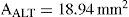
The sample was divided in 2 groups: 5 with an insertion angle of 60° and 5 with angle of 90°. The 10 mini-implants were placed using an air-rotor (Steri-oss LP01-1036 Rev) with a handpiece with a rotation of 20:1 to 100% (minimum speed of 300 and a maximum of 1500 RPM). A protractor was used to guide the miniimplants to their respective angulation (Figure 3). The hip-plaster-bone set was placed in a universal machine for mechanical testing (Instron 5567). An 0.012 -inch stainless steel wire was introduced through the hole in the head of the implant and was fixed to the upper jaw of the machine with a perpendicular direction to the angulation of the screws. The machine acted with a speed of 1mm/min to remove the screw from the bone (Figure 4). The values of maximum force used to calculate the tensile strength were obtained by dividing the contact area of the mini-implant (18.94mm2) and using the following formula:


Where D was the diameter of the screw and g, the length. The average lateral area was:

To determine statistically significant differences between the two study groups a Student's t test was used with a 95% level of signifi cance (p < 0.05).
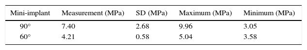
ResultsUpon comparison of the two groups (90 and 60°), it was observed that the numbers obtained in the group of mini-implants placed at 90o presented an average of tensile strength of 7.40±2.68 MPa. There was a statistically significant difference compared to the group with an angle of 60° that presented an average of tensile strength of 4.21±0.58 MPa. Figure 5 shows the trend that the 90° mini-implants presented to resist more traction forces compared with the 60° (Figure 6). Table I shows the average resistance of the two angulations. The average strength of the two angles with their respective standard deviations and the maximum and minimum resistance that each angle endured was assessed.
Discussion

Numerous studies have been carried out to find a way to get anchorage control in orthodontic treatments. Some studies have evaluated the use of skeletal anchorage through mini-implants, since their use seems to be a good option for achieving this objective.
The results obtained in this study showed that there is a significantly higher resistance to tensile forces in mini-implants placed with an angle of 90° (7.40 MPa). Samples placed in the pork hip bone endured 140 N (14 kg) with an angle of 90° and 80N (8 kg) with an angle of 60°. Two of the mini-implants of the group of 90°, suffered a clinically visible deformation.
The sample from the study was small (10 miniimplants, 5 for the angle of 90° and 5 to 60°), because it was designed as a pilot test for future research; but even so, it helps determine the most proper angulation to insert mini-implants. From the physics point of view, the force values coincide because when the force is fully perpendicular (90°), there is a need for greater force in comparison with 60°.
The results agree with those obtained by Pickard and cols,7 their research reported that the miniimplants placed at 90° had a greater force resistance in comparison with angulations of 45° with miniimplants of 6mm in length and 1.8mm in diameter directly in the mouth. Pickard et al. also mentioned that mini-implants can withstand forces ranging from 50 g (0.5 n) to 450 g (4.5 N). In the present study, it can be observed that if the mini-implant length is greater (1,400 g with screws of 8×1.6mm) the resistance to tensile forces in vitro can be increased when compared to using 450 g of force and 6×1.8mm screws placed with 90° angulations, if and when the anatomy where the screw will be placed bears that length. If we compare the results of this study with the force that brackets endure during debonding, it was found in the studies of Yasser Lotfy and Essam that a metal bracket that is subjected to forces immediately after being bonded requires 10 MPa. A mini-implant placed at 90° requires 7.40 MPa; which could show that the force that screws withstand is very similar to those that metal brackets resist when adhered to the enamel surface.
It is important to mention that the present study was conducted in vitro, which helped in not having other factors that could intervene in the eviction of the implant. These factors that can influence miniimplant stability are: bone density (due to the anatomic area).11 The samples where mini-implants were placed were segments of pork hip. In the studies that have been conducted, several types of bone of animal origin, such as beef femur, hip and rib of pig, dog femur and jaws have been used.7Benedict Wilmes6 et al. mentioned that the bone structure that is more similar to the thickness of the cortical layer of the human maxilla and mandible is the pork hip. Tissue around the screw,12 when there is gingival inflammation around the screw, it has influence over stability. Type of implant, Chen Ch13 et al mentioned that mini-implants with a length of8mmarerecommended to obtain a greater load resistance provided that the anatomical area allows it. The mini-implants used in this study are the same length.
Due to the fact that this study was conducted in vitro and factors that can directly influence implant stability such as human bone density, tissue around the implant, or presence of bacterial plaque were not assessed, it is recommended to perform this kind of studies directly in patients’ mouth to measure the effects of these factors over mini-implants.
ConclusionsThe obtained results showed that there is a statistically significant difference between the force that mini-implants placed at 60° compared to 90° resist, the latter exhibiting the highest resistance to traction forces before being removed from bone. Miniimplants with a 90° angle would help increase their stability in orthodontic treatments. The force required to remove a bracket adhered to the enamel surface is similar to the one that a mini-implant with an angle of 90° endures. However, regarding the stability of a mini-implant that is placed in the mouth other factors are involved in addition to the kind of mini-implant: the angle in which it is inserted or the applied force, which can considerably increase or decrease stability. Therefore it is recommended future research to assess these factors.