


The rapid development of wireless broadband communication technology has degraded the location accuracy performance of radio monitoring stations worldwide that use signal angle of arrival (AOA) location technology, and the stations in Taiwan are no exception. In this study, a Federal Communications Commission F(50, 50) broadcast propagation prediction methodology was applied to determine the coverage area of installed TDOA-based monitoring stations in Tainan (i.e., southern Taiwan) metropolitan area. The simulation results indicated that 3 TDOA-based location stations are required to achieve a coverage diameter of 20~30 km. Subsequently, 3 TDOA-based radio monitoring stations [Luzhu, Tainan Gaote, and Tainan health stations (Jinkang)] were installed to locate the radio transmitter that was the source of broadcast interference in Taiwan by monitoring the frequency modulation of broadcast stations at 88.3, 91.5, 89.1, and 91.9 MHz in the Tainan metropolitan, rural, and urban areas, respectively. In this study, the proposed integrated TDOA/AOA location technology was implemented in Taiwan for the first time according to International Telecommunications Union requirements. The location accuracy was within 950 m (50% circular error probability) under multipath conditions in the metropolitan area.
To execute the Telecommunications Act in Taiwan, along with other countries around the world, a radio frequency (RF) monitoring system was installed and improved by government authority (i.e., technical support by vendor) for radio spectrum management to ensure continuous and nationwide communication through various devices [1-3].
Coinciding with Taiwan’s rapid economic development in recent years, widespread urbanization has altered the terrain and environment in areas surrounding radio monitoring stations. Consequently, the location accuracy performance of radio monitoring stations that use signal angle of arrival (AOA) location technology has been seriously degraded [4]. Furthermore, because of developments in communications technology, AOA-based radio monitoring stations are unable to compensate for geographical changes that are affecting the RF environment [5]. This also degrades the location accuracy performance of AOA-based radio monitoring stations.
In Taiwan, along with other countries around the world, the rapid developments of wireless broadband communication technology have appeared. Hence, the amount of interference that occurs when using advanced communication technologies has increased rapidly; for example, the interferences resulting from low transmission power, burst and weak signals, and metropolitan occurs frequently [6-7]. New monitoring and navigation technologies have been developed to identify and then prevent various radio interferences. For example, a time difference of arrival (TDOA)-based location system was proposed to integrate existing AOA-based location systems [8-12].
Advanced countries have installed TDOA monitoring/location stations, such as the regional spectrum monitoring station that was built for the London 2012 Olympic Games [13]. However, urban geographical factors typically inhibit the detection of interference signals. In this study, an integrated TDOA/AOA monitoring system was employed to improve the location accuracy and extend the location coverage area of these monitoring stations [14].
The implementation and experiments are accomplished by proposed integrated TDOA/AOA monitoring system in Taiwan. Hence, the proposed integrated TDOA/AOA scheme was proved to identify, locate, and remove radio interference resulting from low transmission power, burst and weak signals, or metropolitan.
The remainder of this study is organized as follows. Section 2 outlines the design of the TDOA-based monitoring system. The location performance of the TDOA- and AOA-based technologies was analyzed through simulation and implementation, as described in Section 3. In Section 4, the characteristics of AOA and TDOA are compared, and the proposed integrated TAOA/AOA-based monitoring system configuration is discussed. Finally, the conclusion is presented in Section 5.
2TDOA-based monitoring system designThere were effective approaching applied in various scenarios to enhance location accuracy performance [15-17], For the conventional TDOA scheme, two pairs of time-difference of arrival estimates is obtained by using cross-correlation algorithm [18-25]. Subsequently, the obtained two pairs of time-difference arrival of estimation is converted into two pairs of range (distance) difference measurements by multiplying propagation speed of electro-magnetic wave (i.e., 3×10⁸ m/s). Hence, by finding the simultaneous solution of equation group of (1) and (2), the position (XT, YT) is achieved due to two hyperbolic curves are created to determine crossing-point (i.e., the same time-difference of arrival estimation can determine one hyperbolic curve).


where the (XA, YA), (XB, YB) and (XC, YC) denotes the known position of TDOA monitoring station (i.e, longitude and latitude), respectively. Hence, the dij denotes the range (distance) difference between monitoring station #i and #j. Here, (XA, YA) can be referred to as the central control monitoring station configured with central control server. The (XT, YT) denotes an un-known position of measured transmitter (i.e, interference signal).
For direction finding of AOA mode shown in Fig 1, applying the general phase difference is called interferometry is generally applied to calculate the phase difference of arrival in a pair of closely spaced antenna configured in the same monitoring station [26-27].

As shown in Figure 1, the equation (3) is applied to determine the bearing line of measured (inference) signal.

where ∆ϕ, D, θ, f and C denotes the phase difference of arrival measured signal, the distance of two antennas at the same AOA monitoring station, the bearing angle, central frequency of measured signal and propagation speed of electro-magnetic wave, respectively. In order to enhance the bearing accuracy, the multiple pairs (e.g., five pairs or 9 pairs) of antennas are provided with various venders on monitoring system.
In this study, the following radio-spectrum monitoring techniques were applied, as recommended by the 2010 ITU-R Monitoring Handbook [5]: 1) The main disadvantage of TOA-based location technology is that the transmitter and receiver must be synchronized strictly; and 2) TDOA-based monitoring station cannot perform the location mission in stand-alone procedure. However, AOA-based installed in vehicular is easy to achieve multiple bearing line by moving vehicular from one place to another place. Hence, location position (i.e., latitude and longitude) of AOA-based monitoring system is obtained to perform stand-alone mission by single vehicular.
Regarding the various location methods for installing TDOA-based monitoring systems, the design configuration comprises hardware, a cross-correlation and resolving hyperbolic equation algorithm [28-29], a user interface. Importantly, an evaluation criterion is applied to verify the performance of location accuracy. A TDOA technology is applied to perform the time difference of arrival received signal from various monitoring station.
For TDOA technology to obtain an accurate result, the hardware and software used in current experiment must be designed including the performance requirement of the receiver (i.e, scanning speed, receiver sensitivity and third-order intercept point, IP3 requirement etc.), time synchronization, and network connectivity. Fig. 2 shows the system architecture and location requirements for the proposed system.

To install the current monitoring system and further analyze the location accuracy of installed monitoring station, the experimental monitoring station was configured in three stages: hardware selection, software design (cross-correlation algorithm and hyperbolic equation solution), and location error estimation, respectively. Here, signal synchronization is a crucial factor for the successful implementation of TDOA-based monitoring systems. In this study, the TDOA location system employed a global positioning system (GPS) receiver to establish a common time reference.
To obtain a precise location, TDOA technology depends on the frequency, bandwidth, and modulation mode of the received signal, it is key point to process the optimal selection of the sampling rate of measured signal. In this experiment, frequency modulation (FM) characterized with 200 KHz bandwidth is assumed as interference station. The FM transmission signal was detected for a 1-min time interval to execute the TDOA location processing.
Fig. 3 shows that the time stamp of the GPS was synchronous at each monitoring station. When the frequency increased, the sampling time was reduced. The optimization of sampling rate was performed to improve the peak of the cross-correlation results by selecting the appropriate filter bandwidth based on the difference between the arrival times. Compared with AOA technology, TDOA technology is used without applying demodulation during the sampling process. The transmitted signal in the time domain was combined with the GPS time stamp, and the cross-correlation algorithm was applied at the central station.

Regarding the cost of the proposed integrated TDOA/AOA receiver configuration (Fig. 4), AOA-based technology requires a pair of local modular oscillators, a down converter, and a digitizer. Conversely, TDOA-based technology requires only one modular oscillator. In this study, the integrated TDOA/AOA was successfully implemented by applying the AOA or TDOA software algorithm.
3TDOA-based monitoring system simulation and implementation
In accordance with the hardware capability configured in current experimental specifications, a Federal Communications Commission F (50, 50) broadcast propagation prediction methodology was applied to determine the coverage area of installed TDOA-based monitoring stations [30].
Here, the proposed experiential environment is selected in Tainan (southern Taiwan) to investigate the multi-path propagation effect. In order to estimate the proper coverage area via the distance of monitoring station from each-pair, the simulation results is shown in Figure. 5(a)-(d) while various frequency of 30MHz, 300MHz, 1GHz and 3GHz is investigated, respectively.
.30MHz (b).300MHz (c). 1GHz (d). 3 GHz respectively, in southern Taiwan(especially among south of Tainan and north of Kaohsiung).")
.30MHz (b).300MHz (c). 1GHz (d). 3 GHz respectively, in southern Taiwan(especially among south of Tainan and north of Kaohsiung).")
By applying F(50, 50) broadcast propagation prediction methodology, the results show that three TDOA-based location stations need to be installed to cover an area around the diameter of 8km~30km in metropolitan Tainan.
Table 1 shows a summary of the simulation parameters and experimental results, as well as the required number of TDOA-based receivers for the metropolitan area of Tainan.
The applied simulation parameter to estimate the coverage area of required TDOA-based stations.
| The three sites of monitoring station is needed by simulation | ||||||
|---|---|---|---|---|---|---|
| Simulated monitoring station | Frequency | Antenna Factor (AF) | Coverage Area (Km) | Receiver sensitivity | Antenna height (transmitter) | Antenna height (receiver) |
| Kaoshiung Science Park (Central Control Station-Luzhu! | 30 MHz | -4.2 dB | 30 | ≤100 dBm | 2 m | 20 m |
| 300 MHz | 15.8 dB | 15 | ||||
| 1 GHz | 26.3 dB | 15 | ||||
| 3 GHz | 35.8 dB | 8 | ||||
| F(50, 50) radio wave propagation mode is used | ||||||
The results indicate that 3–5 TDOA-based location stations are required to cover a diameter 20~30 km in metropolitan Tainan. Accordingly, Fig. 6 shows the appropriate positions for TDOA-based monitoring stations (within the triangle). As shown in the Figure 6, broadcast stations (88.3, 91.5, 89.1, and 91.9 MHz) were selected to verify the location performance by selecting various measured signals from the center to outside of the TDOA coverage area.

In the trial experiment, the following three monitoring stations were selected to form an appropriate triangular arrangement: 1) Jinkang station in Tainan (TDOA #3, located southern Taiwan metropolitan area); 2) Tainan Gaote (TDOA #2); and 3) Luzhu (TDOA #1, located Kaohsiung Science Park). At the three sites, the distance between Jinkang Station and Luzhu (Kaohsiung Science Park) was calculated as approximately 9.94 km. Fig. 6 shows that using the proposed experimental configuration easily verified the location performance of installed TDOA monitoring stations to perform the multipath effect of metropolitan area [8, 13–14].
In this study, the central station (TDOA/AOA #1 was installed at Luzhu (Kaohsiung Science Park). TDOA #2 and TDOA #3 (Tainan metropolitan area) functioned as remote monitoring stations. These monitoring stations were selected after considering the barrier effect caused by the aforementioned buildings, ground reflection, and the reflected wave.
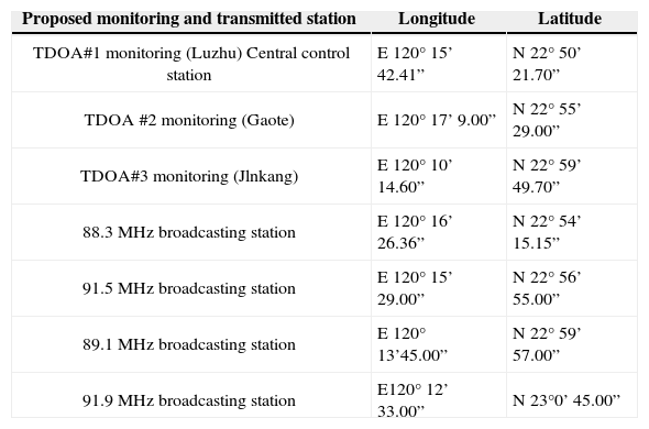
In addition, an upload transmission rate equivalent to that of a 3G mobile network design was required. Table 2 shows the relative position (longitude and latitude) of the TDOA monitoring and transmission stations.
The proposed monitoring and transmission position of the proposed experiment.
| Proposed monitoring and transmitted station | Longitude | Latitude |
|---|---|---|
| TDOA#1 monitoring (Luzhu) Central control station | E 120° 15’ 42.41” | N 22° 50’ 21.70” |
| TDOA #2 monitoring (Gaote) | E 120° 17’ 9.00” | N 22° 55’ 29.00” |
| TDOA#3 monitoring (Jlnkang) | E 120° 10’ 14.60” | N 22° 59’ 49.70” |
| 88.3 MHz broadcasting station | E 120° 16’ 26.36” | N 22° 54’ 15.15” |
| 91.5 MHz broadcasting station | E 120° 15’ 29.00” | N 22° 56’ 55.00” |
| 89.1 MHz broadcasting station | E 120° 13’45.00” | N 22° 59’ 57.00” |
| 91.9 MHz broadcasting station | E120° 12’ 33.00” | N 23°0’ 45.00” |
The three detected signals were simultaneously transferred to the central control station through remote stations, and the time difference among the three pairs of measured signals was determined using the cross-correlation algorithm. Finally, the differences in distance among the three pairs (i.e., Jinkang–Luzhu, Jinkang–Gaote, and Luzhu–Gaote) of measured signals were calculated. Table 3 shows an example of 10 measurements obtained at 88.3 MHz.
An example of FM 88.3MHz for obtaining the distance and time difference of arrival in TDOA scheme.
| Distance Delta(m) | Time Delta(us) | |||||
|---|---|---|---|---|---|---|
| No | (Jlnkang. Luzhu) | (Jinkang, Gaote) | (Luzhu, Gaote) | (Jinkang, Luzhu) | (Jinkang, Gaote) | (Luzhu. Gaole) |
| 1 | 6408 | 11604 | 5196 | 21.36 | 38.68 | 17.32 |
| 2 | 6384 | 11604 | 5220 | 21.28 | 38.68 | 17.41 |
| 3 | 6420 | 11566 | 5148 | 21.41 | 38.52 | 17.16 |
| 4 | 6396 | 11568 | 5184 | 21.32 | 38.56 | 17.28 |
| 5 | 6336 | 11592 | 5280 | 21.12 | 38.64 | 17.52 |
| 6 | 6300 | 11604 | 5316 | 21.00 | 38.68 | 17.36 |
| 7 | 6408 | 11580 | 5184 | 21.36 | 38.60 | 17.36 |
| 8 | 6324 | 11568 | 5256 | 21.08 | 38.56 | 6324 |
| 9 | 6384 | 11568 | 5208 | 21.28 | 38.56 | 6384 |
| 10 | 6396 | 11604 | 5208 | 21 32 | 38.68 | 6396 |
There are three TDOA-based monitoring stations are installed in current experiment. Hence, three pairs of time-difference of arrival estimates is obtained. That is, three pairs of hyperbolic curves is achieved. In order to enhance location accuracy of proposed TDOA monitoring system, it is key point that the user interface is designed to select the proper hyperbolic curve characterized with better location performance shown in Figure 7.

As shown in Figure 7, the power spectrum variation of specific interference signals in time (frequency) domain is displayed in each TDOA-based monitoring station. Hence, there exist the advantages of proposed TDAO-based monitoring system as follows. 1). the waveform variations of interference signals provide a simple method to easy identify the same transmitter (interference station) arrive the monitoring station at the same time by the operator. Hence, the location error resulting from the multi-path propagation effect is decreased significantly. 2). Similarly, the co-channel interference can be significantly suppressed by depending on the power of interference signal coming from the various region.
Fig. 8 shows an example of the measured FM at 88.3 MHz. The target location was calculated based on the measured distances between the pairs of stations, and the hyperbolic location was embedded in the map.

Table 4 shows a summary of the results obtained using the TDOA-based monitoring system. The location errors varied among the various broadcasting stations (88.3, 91.5, 89.1, and 91.9 MHz). The results indicate that the location measurements obtained at 91.9 MHz exhibited the worst location accuracy (the analysis on 50% circular error probability, CEP), which was less than 950 m under multipath conditions.
The summarized results of the experiment for TDOA –based measured locations.
| Location Technology | Frequency (MHz) | Distributed Range(m) | Location accuracy @ CEP 50% (m) | Mean difference (m) | Standard deviation (m) |
|---|---|---|---|---|---|
| TDOA | 88.3 | 20 | 235 | 230.31 | 22.24 |
| 91.5 | 110 | 230 | 260.50 | 76.97 | |
| 89.1 | 350 | 550 | 515.22 | 137.25 | |
| 91.9 | 950 | 950 | 929.26 | 275.76 |
Table 5 shows a summary of the experimental results obtained from the AOA-based monitoring station. Here, compared to conventional AOA-based monitoring system, the proposed integrated TDOA/AOA monitoring system improves locating accuracy of 6 degree.
The summarized result of experiment for AOA –based measured locations.
| Location Technology | Frequency (MHz) | Location angle error (degree) | Location distance (Km) -from monitoring station to measured transmitter | Standard deviation (m) |
|---|---|---|---|---|
| AOA | 88.3 | 5.25 | 7.82 | 700 |
| 91.5 | 3.33 | 12 82 | 730 | |
| 89.1 | 1.58 | 18.50 | 520 | |
| 91.9 | 1.92 | 20.47 | 1200 |
In summary, the experimental process used in the TDOA verification platform, which involved performing three stations at Kaohsiung Science Park, Tainan health stations (Jinkang) and Tainan High Speed Rail (Gaote) station. The AOA test conducted at Kaohsiung Science Park was integrated into the actual verified design and installation at above-mentioned TDOA platform stage. Fig. 9 shows a flow chart for the proposed system implementation.

There are three phases are included 1). The monitoring site (station) and the design of hardware, software and user interface specification. The station need to keep away from complex communication environment to avoid improper interferences. 2). In order to investigate the relationship between geometric positon of interference transmitter and accuracy performance of proposed TDOA monitoring system, the experimental scenario is designed as above-mentioned in Fig. 6. 3). The circular error probability (CEP) is used to estimate the accuracy performance of proposed TDOA monitoring system.
4The proposed integrated TDOA/AOA-based monitoring systemThe advantages and disadvantages of AOA-based and TDOA-based monitoring systems are summarized as follows:
- 1)
TDOA-based monitoring systems are suitable for identifying suspicious interference and low-power and burst signals. However, AOA-based monitoring systems should be established in locations that are free of obstacles and ground reflections to minimize the location errors resulting from reflected radio waves.
- 2)
The configuration of TDOA-based systems is comparatively simple and inexpensive (saving 10%–20% of the total cost), whereas AOA-based systems require complex antenna arrays.
- 3)
Unlike AOA-based system, TDOA-based monitoring systems are unnecessary to process antenna calibration on open air environment, and are easy to repair when the antenna is damaged.
- 4)
Regarding location accuracy performance, TDOA-based systems are superior within the area of coverage, although the performance declines outside of the coverage area.
- 5)
In contrast with the minimal data bandwidth requirements of AOA-based systems, TDOA-based systems require a high-speed broadband network connection, particularly when the upload rate is higher than 1 Mbps. Moreover, determining the precise time is required for synchronizing TDOA-based systems.
The performance of the proposed TDOA/AOA monitoring system demonstrates that integrating the advantages of AOA and TDOA-based technologies improves location accuracy performance within the coverage area, and provides stronger anti-interference capabilities.
Fig. 10 shows the advanced application that the fixed TDOA/AOA monitoring station was installed on a high mountain next to a metropolitan area. However, the mobile TDOA monitoring station was fitted to a vehicle that moved randomly throughout the metropolitan area. The AOA-based system calculated the bearing of the vehicle as a straight line, whereas the TDOA-based receiver presented a hyperbolic curve. This demonstrates that the proposed AOA/TDAO monitoring system can prevent broadcast interference in metropolitan areas.

The basic architecture of intergraded TDOA/AOA monitoring system is sown as Fig 11. the up-load transmission rate of a 3G mobile network design was needed.

The proposed integrated TDOA/AOA scheme shown in Fig. 11, after TDOA location approaching executing the acquiring processing of detected signal, the two detected signals are transported to the central control station (e.g., TDOA/AOA monitoring station) from the remote fix monitoring station #A and mobile monitoring station #B simultaneously.
For TDOA calculating processing, the time-difference of arrival of pair of detected signals is obtained by using a cross-correlation algorithm via selecting the proper sampling rate on detected signals. Finally, the hyperbolic curve is determined by applying the random one of equation (1). In addition, for AOA calculating processing (i.e, phase interferometry) presented in Figure 1 and calculated by equation (3), the phase difference of detected signals is achieved and then the bearing line of transmitter (interference signal) is created. Hence, the hyperbolic curve of mobile TDOA approaching and the bearing line of fix AOA approaching are appeared in fix TDOA/AOA station simultaneously to determine location of detected signals (i.e., the longitude and latitude position).
In addition, to further avoid the telecommunication networking (i.e., 3G networking) blocking and break-down that occurred in proposed integrated TDOA/AOA system, the measured signal (i.e., each specific frequency of 88.3 MHz, 91.5 MHz, 89.1 MHz and 91.9 MHz in current experiment) is recorded as 200 seconds in a storage file of 3-4 M bytes accordance with the measured signal that played back in central control server (i.e., remote central control monitoring station) to determine the interference location (i.e., the longitude and latitude) of (XA, YA).
Based on the integrated TDOA/AOA configuration used in Taiwan, the interferences resulting from low transmission power, burst and weak signals, or metropolitan can be identified, located, and removed to ensure the effective management of radio spectrum by government authority. Fig. 12 shows that the major advantage of the integrated TDOA/AOA monitoring system is that it can extend the coverage area and improve the location performance of AOA-based monitoring systems that are currently installed for current experiment in Taiwan. Here, the TDOA-based system provides better location performance in the surrounding range of triangle coverage area configured by three monitoring stations.

By contrast, an AOA-based monitoring system was suitable for the inside as well as outside of coverage area in a monitoring system. Therefore, the architecture and equipment specifications of the proposed TDOA-based system are anticipated to resolve low transmitted power, burst and weak signals, and metropolitan interference problems and improve the monitoring network. Hence, Compared to conventional AOA-based monitoring system, the proposed integrated TDOA/AOA monitoring system increase 2 times coverage area.
5ConclusionThe conventional AOA-based monitoring system is hard to apply on solving interference in metropolitan due to the multi-path effect. In current study, the proposed integrated TDOA/AOA monitoring system had been configured and implemented with the coverage diameter of 20km~30km by applied F(50, 50) broadcast propagation prediction methodology applied by Federal Communications Commission (FCC). Under multi-path effect, by applying practical experiment for locating various frequency modulation (FM) signal, the locating accuracy at circular error probability (CEP) 50% is less than 950m (235m) distance away from the outside (inside) of monitoring coverage area in metropolitan area. Compared to conventional AOA-based monitoring system, the proposed TDOA/AOA monitoring system improves locating accuracy of 6 degree and increase 2 times coverage area. Therefore, the proposed TDOA/AOA system can be applied and the interference transmitter characterized by low transmitted power, burst and weak signals, and metropolitan interference can be easily identified, located, and removed.
This study was supported under grant No. NSC 102-2221-E-244-001 by the National Science Council and by the Special Interference Prevention project of the National Communications Commission in Taiwan. Also, we are thankful for National Instruments (NI) and Telecom technology center (TTC) in Taiwan providing essential measured equipment and technical consultant, respectively.