


The viaduct over the River Deba on the Basque-Y high-speed rail line crosses the river valley in an area near Bergara, a town in the Spanish province of Guipuzcoa. The deck is a prestressed concrete box girder with variable depth over the piers. Built with an underslung movable scaffolding system (MSS), its span arrangement is 50+80+70+60+3×65+70+65+70+3×65+45m.
On the back of developments in recent years in Spain, the technology could be deployed to build the main 80m span, setting a national record for high-speed rail span length using this building system.
The article contains a detailed description of the characteristics of the viaduct, as well as its construction and the monitoring systems applied during its erection.
El viaducto sobre el río Deba en la Y-vasca de alta velocidad permite el paso del ferrocarril sobre la vaguada por la que fluye el río Deba en las cercanías de la localidad de Bergara. El viaducto presenta un tablero con sección cajón de hormigón pretensado con canto variable en la zona cercana a pilas, que se ha ejecutado con autocimbra, con una distribución de luces de 50+80+70+60+3×65+70+65+70+3×65+45m.
El desarrollo de la tecnología que han experimentado las autocimbras en los últimos años en España ha permitido llegar a un vano principal con 80 m, que supone el récord de luz en alta velocidad ejecutado con este sistema.
El artículo describe con detalle las principales características del viaducto, así como su proceso constructivo, y los sistemas de control y monitorización empleados durante la ejecución.
This article contains a detailed description of the background, design and construction of the River Deba Viaduct on the Bergara–Bergara section of the ‘Basque-Y’ high-speed railway line and some brief mention of the other less noteworthy structures comprising this section of the line.
1.1Structures on the Bergara–Bergara section of the high-speed lineThe River Deba Viaduct (Fig. 1), described in detail in a later section, straddles a deep river valley near the town of Bergara, towering more than 90m over the ground below. While 900m apart at deck elevation, the valley's relatively sharp sides form a fairly symmetrical ‘V’, although this symmetry is briefly broken by the Vitoria/Gasteiz-Eibar motorway near abutment E-1 between piers P-1 and P-2 (upper right, Fig. 1).

Three further viaducts lie on the Bergara–Bergara section:
- -
Lamiategui Viaduct, with a total length of 425m and a span arrangement of 30+8×40+35m (Fig. 2);
- -
Altzeta Brook Viaduct, with a total length of 140m and a span arrangement of 30+40+40+30m (Fig. 3);
- -
Olzaileko Brook Viaduct, with a total length of 100m and a span arrangement of 30+40+30m (Fig. 4).


These three viaducts were designed and built with typical 40m spans to capitalise on ancillary resources and systematise construction. The three decks are constant depth prestressed concrete box girders. Since the height over the terrain is moderate in all three, they were erected using shoring towers, thereby eluding the need for conventional shoring, which would have had a heavier impact on the ground below.
2Background for River Deba Viaduct designIn 2007, the Basque Railway System (Euskal Trenbide Sarea, ETS) called an ideas competition to award the design of the Bergara–Bergara section of its ‘Basque-Y’ high-speed line, intending for the River Deba Viaduct to constitute the emblematic structure on the line, given its visibility from many perspectives, fruit of its total length (900m) and substantial height (90m).
The alignment for the high speed railway across the River Deba Valley had also to accommodate a number of ground-level roadways, which largely determined its span lengths. The viaduct crosses the Vitoria Gasteiz-Eibar motorway very obliquely between KP 2+780 and KP 2+840, the GI-627 and GI-632 roads at around KP 3+150, the River Deba at KP 3+230, and new road GI-632 approximately between KPs 3+340 and 3+370, as well as a number of smaller roads, one very close to abutment E-1.
Given the enormous height of the viaduct and its location in a very visible valley, the solution chosen sought to harmonise the structure with the landscape and minimise the impact on the surrounds, both in keeping with terrain-independent deck construction.
The winner of the ideas competition, a unique solution that met all the aforementioned conditions, was submitted by the IDEAM S.A.-Euroestudios joint venture.
The need for long spans, some measuring 80m or more, to accommodate the under-bridge conditions informed the choice of an incrementally launched truss deck solution, with a span arrangement of 50+70+60+70+110+180+110+3×60+50m, two large, V-shaped central piers to reduce the number of support points on the ground and a 180m centre-most span (Fig. 5).

After the design was awarded, at the urging of ETS, the V-shaped pier solution that won the ideas competition was adapted during the typology study phase to a vertical pier solution, in pursuit of a lesser visual impact and greater transparency in the valley, while simplifying construction and lowering costs. The incrementally launched composite truss deck design was retained, but adapted to consist in three large central spans, 100+110+100, the widest of which would straddle the entire riverbed. The approach spans were dimensioned to around 80m, for a final arrangement at this stage of 50+80+3×75+100+110+100+2×80+70 (Fig. 6).

In early 2009, with the economic crisis in full swing and after several alignment adaptations that retarded the preliminary design by nearly 2 years, the owner's changing requirements and priorities necessitated a study of alternatives with more modest spans to adapt the viaduct to the following general conditions:
- -
to impact the roads and motorways below, as well as the River Deba riverbed, as little as possible;
- -
to pursue terrain-independent construction, given the height of the viaduct;
- -
to retain the status of the viaduct as an emblematic structure on the Basque-Y line;
- -
to ensure the compatibility between the aforementioned conditions and harmonisation with and a minimal visual impact on the surrounds;
- -
to lower the cost of the earlier solutions by shortening the standard span length as far as possible.
With these new boundary conditions and with the imperative of respecting a minimum 80m span in the oblique crossing over the Vitoria/Gasteiz-Eibar motorway, the design completed in 2009 (hereafter the original design) envisaged an incrementally launched deck somewhat more conventional than the composite truss initially studied. The solution consisted in a box girder with double composite action in hooging areas. This solution was analogous to designs authored by IDEAM for earlier composite high-speed rail viaducts such as “Arroyo las Piedras” [1], the first such structure built in Spain, and Archidona Viaduct [2], the world's longest bridge with no intermediate expansion joints or joint systems in the track.
The composite deck cross-section was designed to a total depth of 5.50m and a steel girder depth of 5.04m, just under the standard transport ceiling. The standard spans were to measure 80m and their arrangement was a very uniform 50+10×80+50m, with eleven piers in the valley, one more than envisaged in the truss deck solution. Fig. 7 is an elevation sketch of the solution adopted in the original design and Fig. 8 a simulation of the viaduct in its surrounds.


The steel box girder was to be painted dark green to blend the viaduct as fully as possible into the landscape, a valley with a dense plant cover and a prevalence of intense green shades (Fig. 8).
This highly uniform and balanced span arrangement, including ten standard 80m spans, was to stretch obliquely across the Vitoria/Gasteiz-Eibar motorway as mentioned, while meeting all the boundary conditions imposed by roads GI-632 and GI-627 as well as the River Deba. It would have impacted only the Bergara-side approach to the Vitoria/Gasteiz-Eibar motorway toll station (new dual carriageway road GI-632). By only slightly realigning the approach lane, the resulting original design yielded a harmonious viaduct with an absolutely uniform and structurally balanced span arrangement (Fig. 9).

Impacting the approach lane to the toll motorway or any other road, while not accepted by the owners in the early phases of the typology study and preliminary design, was consented to in the original detailed design phase. Alternatives that would not affect the under-bridge toll station approach lane would have led to solutions with standard spans wider than the 80m initially proposed for the composite truss decks. In the new economic context prevailing in 2009, the high cost of solutions with 100m or 110m centre spans appeared to be unjustified in light of the minor impact involved in the design adopted and its ready solution with a slight realignment of the toll station approach lane.
3Initial exclusion of concrete solutionsIn the competition phase and subsequent typology study and preliminary design stages, alternative conventional solutions such as prestressed concrete box girders were also reviewed.
The three possible construction methods for concrete viaducts are:
- -
span-to-span with movable scaffolding (MSS);
- -
incremental launching;
- -
balanced cantilevering.
At the time, these solutions were ruled out for the reasons discussed below.
3.1Span-to-span concrete constructionAt the time of the competition (2007) and when the original design was being drafted (2009), the maximum span lengths on high-speed rail viaducts with MSS-erected prestressed concrete box girders built in Spain ranged from 60m to 66m. Prior to 2007, the record length in Spain for this type of structures was held by “Arroyo del Valle” Viaduct, which spanned a 66m gap between piers no more than 80m high [3]. The country's tallest high-speed rail viaduct piers, rising to an elevation of 93m, had been built for the “Arroyo las Piedras” Viaduct, with an incrementally launched composite deck and 63.5m standard spans [1].
As designing and building a span-to-span prestressed concrete box girder for the 900m River Deba Viaduct at a height of around 90m with spans at least 80m long was not technically feasible in Spain at the time for want of movable scaffolding apt for such dimensions, that solution was ruled out.
3.2Incremental launching with concreteAnother alternative for building a concrete deck might have been incremental launching. Nonetheless, the height (over 85m), length (900m) and standard span (80m) of the River Deba Viaduct placed it on the outer bounds of this method of high-speed rail construction at the time in Spain.
Whilst incremental launching with concrete may initially be suitable for spans ranging from 60m to 80m, this solution was ruled out in the original design (2009) in favour of the equivalent alternative, namely incremental launching of a composite deck.
Incremental launching of a heavy concrete deck over very flexible, 90m tall piers was regarded as a scantly suitable procedure that would jeopardise the safety of both the structure and the under-bridge. Moreover, the functional viability of the operation itself was found to be questionable, given the need to envisage exceptionally powerful lifting jacks in the event of having to replace any of the many launching bearings due to Teflon surface jamming, damage or bending, which is not at all uncommon during concrete launching.
This alternative was less technically suitable than composite deck solutions for the following reasons.
- -
The 80m spans, and especially the 100m and 110m spans initially envisaged, would necessitate costly non-conventional provisional ancillaries such as stay cable towers.
- -
Since the weight of concrete decks is incompatible with the speedy launching needed to span the gap over roads and motorways in a single night, the use of these roadways would have to be severely restricted for reasons of safety until the cantilever front had completely cleared that distance. Composite deck launching speed is much greater, for such members weigh much less and, as they move directly over sliding bearings, the operating time needed to cover sensitive areas is shorter, minimising safety risks.
- -
Resorting to incremental concrete launching over very tall piers is less advisable than composite alternatives for both technical and safety reasons, for the lower weight of the latter significantly reduces the stress on the piers during construction, enhancing safety during this stage.
- -
The greater flexibility of composite than concrete solutions also mitigates the strength and structural constraints inevitably imposed by the geometric tolerances entailed in launching, which minimises both the differential elevation movements between piers and the need to monitor sliding bearing performance.
In short, incremental launching of a concrete box girder across spans of at least 80m was ruled out in favour of the alternative use of a composite deck for reasons of safety, shorter construction times and savings on ancillaries during launching.
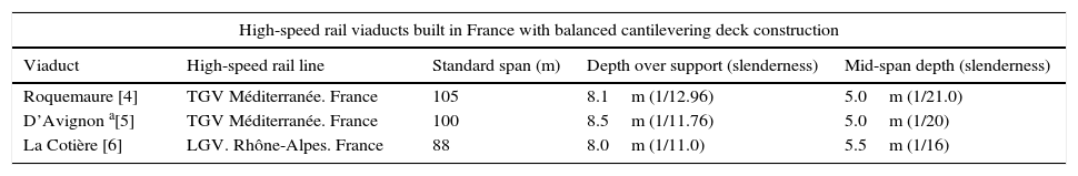
3.3Balanced cantilevering with concreteNo prior experience had been accumulated in Spain in the balanced cantilevering construction of spans on a high-speed rail viaduct straddling distances of 80–100m between such tall piers.
French experience with this typology was limited to the viaducts listed in Table 1.
Main high-speed rail viaducts built in France using the balanced cantilever method in multi-spans.
| High-speed rail viaducts built in France with balanced cantilevering deck construction | ||||
|---|---|---|---|---|
| Viaduct | High-speed rail line | Standard span (m) | Depth over support (slenderness) | Mid-span depth (slenderness) |
| Roquemaure [4] | TGV Méditerranée. France | 105 | 8.1m (1/12.96) | 5.0m (1/21.0) |
| D’Avignon a[5] | TGV Méditerranée. France | 100 | 8.5m (1/11.76) | 5.0m (1/20) |
| La Cotière [6] | LGV. Rhône-Alpes. France | 88 | 8.0m (1/11.0) | 5.5m (1/16) |
As may be surmised from the table, the world record for multi-span variable depth concrete decks of this nature built using balanced cantilevering is held by Roquemaure Viaduct on the French TGV Méditerranée line, which has standard 105m spans. Be it said, however, that in all cases where this procedure has been used in France, the pier heights were much lower than on the River Deba Viaduct.
The spans envisaged in the preliminary stage, with lengths of 100–110m, lay outside the normal range for this typology, which was consequently ruled out. For the span arrangement envisaged in the original detailed design drafted in 2009, with standard spans of around 80m, balanced cantilevering was not technically suitable for reasons of basic safety or feasibility, as follows:
- -
At the time the erection gantries in Spain had neither the dimensions nor the technical features needed for spans in this range on high-speed rail. Given the number of piers involved (11–13 depending on the span length), a large number of gantries would have had to be manufactured to complete the works in a reasonable time. That, given their improbable re-use, would have meant amortising all those gantries with this project alone. The solution was therefore ruled out for reasons of cost and turnaround times.
- -
Any reasonably timed construction programme would have necessitated complex works planning to simultaneously conduct several gantry, reinforcement assembly and concrete casting operations. Given the complex under-bridge conditions, with a raft of roadways, a motorway (AP-1) and urbanised areas, transporting the material to the deck elevation would have posed serious problems: pumping concrete to each cantilevered front at heights of over 90m, for instance. All the foregoing would have necessarily meant simultaneously deploying several large cranes and concrete pumps, inadmissibly inconveniencing under-bridge road and motorway traffic as well as nearby factories and residential areas and risking unacceptable environmental impact on the forest and plant life below.
- -
Simultaneously operating a number of gantries with fronts crossing motorways, roads, factories and nearby residential areas would have entailed the risk of possible construction incidents that should be eluded when other safer procedures are available.
- -
Not a single high-speed rail multi-span viaduct with long spans and piers up to 90m tall had been built anywhere in the world using balanced cantilevering.
For all the foregoing, this solution was likewise ruled out in the original design. The conclusion drawn in the original design drafted in 2009 was that for reasons of technical feasibility, construction safety, harmonisation with the landscape, minimisation of environmental impact and cost, the best solution for standard 80m spans was an incrementally launched composite deck as described at the end of the preceding section (Fig. 8).
4Description of the solution ultimately builtWhen at year-end 2011 the Bergara–Bergara section was awarded to the Abergara joint venture formed by SACYR, CAMPEZO, CYCASA, and FEBIDE, adjustments were proposed to elude the need to realign the Bergara side approach to the AP-1 toll station by reducing the standard 80m length of the River Deba Viaduct spans wherever possible.
The 70m standard span arrangement with just one 80m span over the motorway proposed by the contractor enhanced the feasibility of the somewhat less costly solution of using movable scaffolding to build a prestressed concrete box girder. This approach could be adopted in the detailed design thanks to progress in ancillary resource technology for the span-to-span launching of concrete decks introduced by Grupo Puentes y Calzadas, the Abergara joint venture's deck subcontractor. The company had recently designed and manufactured a movable scaffolding system able to accommodate high-speed rail decks with 70–80m spans. With this technology, the River Deba Viaduct set a national record in Spain for this type of bridge.
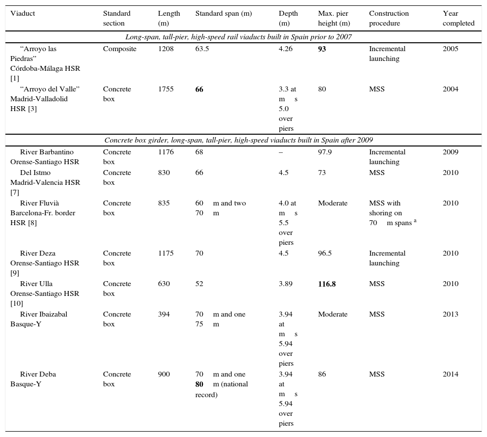
Table 2 lists the most prominent long high-speed rail viaducts with large spans and tall piers built in recent years in Spain.
Long-span, tall-pier, high-speed rail viaducts in Spain.
| Viaduct | Standard section | Length (m) | Standard span (m) | Depth (m) | Max. pier height (m) | Construction procedure | Year completed |
|---|---|---|---|---|---|---|---|
| Long-span, tall-pier, high-speed rail viaducts built in Spain prior to 2007 | |||||||
| “Arroyo las Piedras” Córdoba-Málaga HSR [1] | Composite | 1208 | 63.5 | 4.26 | 93 | Incremental launching | 2005 |
| “Arroyo del Valle” Madrid-Valladolid HSR [3] | Concrete box | 1755 | 66 | 3.3 at ms 5.0 over piers | 80 | MSS | 2004 |
| Concrete box girder, long-span, tall-pier, high-speed viaducts built in Spain after 2009 | |||||||
| River Barbantino Orense-Santiago HSR | Concrete box | 1176 | 68 | – | 97.9 | Incremental launching | 2009 |
| Del Istmo Madrid-Valencia HSR [7] | Concrete box | 830 | 66 | 4.5 | 73 | MSS | 2010 |
| River Fluvià Barcelona-Fr. border HSR [8] | Concrete box | 835 | 60m and two 70m | 4.0 at ms 5.5 over piers | Moderate | MSS with shoring on 70m spans a | 2010 |
| River Deza Orense-Santiago HSR [9] | Concrete box | 1175 | 70 | 4.5 | 96.5 | Incremental launching | 2010 |
| River Ulla Orense-Santiago HSR [10] | Concrete box | 630 | 52 | 3.89 | 116.8 | MSS | 2010 |
| River Ibaizabal Basque-Y | Concrete box | 394 | 70m and one 75m | 3.94 at ms 5.94 over piers | Moderate | MSS | 2013 |
| River Deba Basque-Y | Concrete box | 900 | 70m and one 80m (national record) | 3.94 at ms 5.94 over piers | 86 | MSS | 2014 |
Prior to the development of the MSS designed by Grupo Puentes, this procedure had been used on high-speed rail in Spain for prestressed concrete decks with maximum span lengths of only 65mm to 66m. For that reason, the procedure was ruled out in the original design for the River Deba Viaduct, drafted in 2007–2009.
4.1Deck descriptionThe solution designed by IDEAM for the Abergara joint venture, which was the one ultimately built, envisaged a span arrangement of 50+80+70+60+3×65+70+65+70+3×65+45m across the total 900m length, with one 80m span and standard spans measuring 70m and 65m (Fig. 10). The 80m span is the longest span ever built with an MSS for high-speed rail in Spain.

As described earlier, the viaduct was built using an MSS from abutment E-2 to abutment E-1 with a single point of fixity on abutment E-2, which resisted the longitudinal braking and start-up forces, as well as the friction on the other sliding bearings. A track expansion joint was fitted to abutment E-1.
The viaduct has 13 piers in the valley with heights ranging from 23m to 86m. Their section is variable, as discussed below.
The deck cross-section is a prestressed box girder with a depth varying from 3.94m at mid-span to 5.94m over the piers, for a depth/span ratio in the longest (80m) span of 1/21.05 and of 1/13.46 over the piers (Fig. 12). The variation in depth was limited to 15m from the bearing centreline on each side of the pier to maintain the same depth in the formwork moulds for these sections, irrespective of the span length. As the depth in the rest of the span was constant (accounting for 53% of the 65m spans and 62% of the 80m span), the overall impression is of a very slender deck (Fig. 11).

 and over piers (right).")
Box width varies at the bottom around the piers and is constant at approximately 6.6m across the rest of the span, where the depth is likewise constant. As the slant on the webs is constant throughout, in the centre of the span the top web projects by 0.955m on each side with respect to the bottom. The resulting box is 8.521m wide at its abutment with the 2.739m wide side cantilevers, which vary in thickness from 0.41m at the springing to 0.20m along the rim.
Further to standard practice, the hollow interior in the trapezoid section is bevelled on the inner corners both to improve bottom deck resistance to transverse bending and shear and to house the prestressing anchors.
The solid bulkheads built into the areas of the box over the piers are fitted with a manhole to provide for inspection of girder interiors. The piers, in turn, are fitted with vertical accesses to review and replace bearings.
4.2Description of substructure4.2.1Deck-substructure connections BearingsEach pier/abutment carries one fixed and one free spherical bearing in the transverse direction, whereas all the longitudinal bearings are free with the exception of the ones on the four tallest centre piers (P-6 to P-9), which are fixed. Elastically securing the deck to the tallest piers, up to 86m high, ensures the control of strain on the four highest pierheads by limiting the maximum movement to the thermal expansion or thermal+shrinkage and creep-induced contraction accumulating in the deck from the point of fixity on abutment E-2. Given the substantial flexibility of the centre piers, this limitation of the maximum longitudinal strain on the pierheads induces loads similar to those that would be induced by friction if the longitudinal bearings had been designed to be free. With that arrangement, second order strain due to pierhead buckling-related instability on the tallest piers can be controlled, reducing longitudinal stress and enhancing pier strength.
All the bearings are positioned conventionally, with the stainless steel tray lying on the sliding element (Fig. 13), which is horizontally level except on abutment E-1. There it is parallel to the slope of the deck in the area to prevent longitudinal deck movements from inducing differential vertical movements on the track around the expansion joint, which could cause passenger discomfort.

Flexible, removable and replaceable protective covers were fitted to the bearings to prevent soiling and concomitant extra wear on the sliding stainless steel tray on the top element, which is longer than the bottom part of the support to accommodate deck expansion and contraction. These covers enclose the bearings completely, protecting them from sand and dust (Fig. 13).
The sliding element on the spherical bearings is a high molecular density polyethylene membrane, a material that improves on the more conventional Teflon, with manufacturer-guaranteed 2% maximum friction at very low temperatures, which is lower than the 3% delivered by their PTFE Teflon counterparts. Such greater durability ensures lower bearing maintenance costs in future.
The bearings were also fitted with side rulers to determine, in routine inspections, the position of the stainless steel top tray with respect to the bottom component and hence the exact position of the deck relative to the pier (Fig. 13).
All the bearings are replaceable and from the outset the design envisaged the position for and expected reactions in the jacks required for replacement, as appropriate.
4.3. Piers and abutmentsPier conception and design was an arduous task in which a complex balance between aesthetics and ease of construction was sought in the detailed design phase. While not neglecting the latter, particular care was taken in the design of the viaduct piers to deliver an elegant solution harmonious with the surrounds, characterised by a softened geometry that departs from conventional rectangular wall piers, felt to be overly austere in such a tall and visible viaduct as this one over the River Deba.
Viewed frontally (Fig. 14), the pier section increases gradually and radially from the top down, with the minimum transverse dimension, 6.50m, at the head.
, and frontal and oblique (b and c) elevation views.")
In the longitudinal direction, pier depth varies linearly from the crown, where the width is 3.50m, to the base, which measures 6m in the tallest piers (Fig. 14).
In the cross-section, the outer rectangle is heavily bevelled at the corners, in parallel on the two sides. This generates a series of oblique planes commensurate with the varying geometry of the sides with variable depth, affording the pier a less abrupt and much more elegant aesthetic than the classic matchbox design (Fig. 15).

The lateral faces bear a recess in the middle flanked by symmetrical sides that widens from the top down to generate a V-shaped groove, slenderising pier geometry (Fig. 15).
The piers are hollow with inner walls varying in thickness from 0.30m in the top 25m to 0.40m in the middle 25m and 0.50m in the lower section of the tallest piers. The tallest pier, on the bank of the River Deba, is 86m high.
Abutment E-1 is designed in the form of a closed box to house the track expansion joint, whilst abutment E-2, over which the track is continuous, is the point of fixity for the deck.
All the foundations are shallow except under piers P-7 and P-8 alongside the River Deba riverbed, each of which rests on pile caps joining 15 piles with a diameter of 1.8m.
5Construction5.1FoundationsThe excavation for most of the piers posed difficulties due to their location near roads or the river or on steep slopes that called for significant provisional shoring [11]. As noted, the foundations under piers P-7 and P-8, adjacent to the River Deba, consist in fifteen 1800mm ϕ piles, all of which were fitted with reusable sheathing in the uppermost metres of the bank.
The excavation shoring for piers 1, 7, 9 and 13 consisted in 168mm×12.5mm tubular micropìle walls and soil anchors positioned at different depths (Fig. 16a). The sacrificial sheet pile retaining wall built around the pier closest to the river, pier 8, also provides environmental protection and protection for the pile cap against possible soil washouts (Fig. 16b). At pier 10 the excavation slopes had to be secured with several rows of soil anchor pins and shotcreted over welded wire fabric (Fig. 17).
 Micropile retaining walls for P-7 foundations; b) sheet retaining wall for P-8 pile foundations.")

The climbing forms used to build the variable geometry piers were assembled into modules 5m high (Fig. 18). The piers were divided into two areas, one to cycle 8, at 40m from the pier head, and the other from that height to the base, at a distance of 86m in the tallest piers.

Each formwork module consisted in eight separate sections for the outer sides and a split box mould for the inner sides. The climbing system consisted in a platform fitted with spreader beams (Fig. 18). Dihedral steel plates were set at the corners to accommodate the dimensional variation with height.
The speedy pace of production, in which one 5m cycle was completed every two days, was attained by fully pre-assembling the reinforcing steel on the ground on variable geometry frames and hoisting it into position with mobile cranes (Fig. 19a).

In the piers with heights of under 40–45m, the concrete was pumped to the forms (Fig. 19b), while in the taller central members it was cast from crane-lifted 2m3 buckets; the production rates were 24m3/h and 12m3/h, respectively.
5.3Deck constructionAs noted earlier, the deck was built with underslung movable scaffolding that carried the formwork on top. In the casting stage, the MSS rested on the forward pier ring and was slung from a hanger beam supported at the end of the preceding cantilevered section (Fig. 20). When moving forward, it rested on two or three rings (Fig. 21) until reaching the construction position, when it was secured at the rear to the preceding hanger beam.


Deck construction was divided into 14 phases, in each of which the rear span was completed and a section was cantilevered into the forward span, resting on the 155m long MSS. During the reinforcing steel assembly and concrete casting phases, the scaffolding hung as a statically determinate structure from the cantilever built in the preceding phase and rested on the steel structure (ring) secured to the forward pier. The standard gap between scaffolding supports was 50m in the 65m and 70m spans and 55m in the 80m span. The cantilevered sections, designed to limit the gap between supports during concrete casting, were 15m, 20m or 25m long depending on the length of the forward span.
Construction in the phases with 15m cantilevers proceeded as follows. The rebar for the bottom slab and webs (forming a U-section, trough-like structure) was positioned across the entire section and subsequently cast in concrete (Fig. 22). The positive reinforcement in the central, constant depth area was prestressed and the statically determinate precast slabs were laid over top of the previously cast U (Fig. 23), resting on provisional braces. The top slab rebar was then laid across the entire section and cast in concrete (Fig. 24). The negative reinforcement in the variable depth area was stressed from the edge of the ring, after which the parabolic tendons ensuring continuity with the preceding phase were likewise stressed. Lastly, the provisional braces were removed from the non-structural precast slabs.
.")


In the phases with 20m and 25m cantilevers, namely the phases prior to the 70m and 80m spans, for reasons of MSS strength constraints, deck construction was divided into four sub-phases. First, the rebar was laid in the trough-like structure across the entire section (Fig. 22) and concrete was cast in the section of the trough running from the cantilever to the forward pier and for an equivalent distance towards mid-span. The precast slabs were then laid in this area of the trough, the rebar for the top slab was assembled over the precast slabs and cast in concrete and the top slab negative reinforcement units were stressed. The concrete for the mid-span constant depth trough section was then poured and the positive reinforcement located in the mid-span area of the bottom slab was stressed. In the following step the precast slabs were laid over the U in the mid-span area (Fig. 25), after which the top slab rebar for that area was assembled and cast in concrete. Lastly, the family of parabolic continuity tendons was stressed and the MSS was unslung and advanced to proceed to build the following phase.

Fig. 26 shows the front end of the cantilever and, resting on it, the upper transverse hanger beam from which the movable scaffolding is hung, the prestressing anchorages for the family of parabolic continuity tendons in the webs and the anchorages for the prestressing in the hogging area of the top slab. Fig. 27 depicts the inside of the deck, with the anchorages for the mid-span positive reinforcement stressing in the background.


Continuity between the parabolic prestressed tendons was established by crosslinking cables and using double wedge anchors (Fig. 28), which were preferred by the deck subcontractor over conventional couplers.

Deck construction productivity ranged from 2 weeks (in sections with 15m cantilevers) to 2.5 weeks (in sections with 20m cantilevers) per section. The entire deck was erected between October 2013 and July 2014. Such high productivity, given the variability of the cross-sections and the phase-based construction described, was attained by industrialising U-section rebar assembly, including the alignment of the prestressing sheaths, module-by-module on the ground. After assembly, the modules were lifted onto the deck with mobile cranes and driven on lorries to the forward end of the phase, where they were laid with the aid of a portal crane (Fig. 29). After the precast slabs were laid across the troughs, the rebar for the top slab was assembled in situ.

At 80m, span 2, which straddles toll motorway AP-1, set the national record for span length on high-speed rail viaducts built using this construction method (Fig. 30). In this phase the MSS was launched with the aid of temporary shoring located 10m from the P-2 centreline to slightly reduce bending on the forward end of the scaffolding during advance operations.

In addition to the adoption of routine individual and collective safety measures, special portal frames were installed over the existing roadways as protection against possible falling objects.
5.3.1Resting movable scaffolding on piersAs an underslung system, the scaffolding was secured to the piers with bracket-like rings. Given their enormous weight, these rings were hoisted to the tops of the lower piers with mobile cranes and to the crown of the taller piers with a system of pulleys (Fig. 31), eluding the need for heavy duty cranes for these operations.

The support rings for the movable scaffolding consisted in two steel triangular cells with a prestressed horizontal tie that joined the two cells on both sides, and slanted braces balanced with two vertical uprights (Fig. 32). The load induced by the MSS and the deck under construction was transferred to the pier by two supports, one upper and one lower, on each side.

The upper support transferred the transverse reactions to the pier, along with any longitudinal friction induced by forward MSS motion. This support worked in compression thanks to the stressed bar-mediated prestressing at the connection between the two cells, preventing their separation due to the tensile stress on the upper horizontal tie when the ring was subjected to the weight of the scaffolding.
The vertical load generated by the MSS, received by the braces and transferred as slanted compressive stress to the lower support, was decomposed into compression stress normal to the pier and a vertical reaction also absorbed by the pier by means of a Teflon bearing housed in an opening in its side.
6Viaduct instrumenting during constructionA series of measurements were taken during construction to monitor deck erection and the actual forces transferred to the structure. Instruments were installed to monitor the reactions generated by the movable scaffolding both at the front end of the rear phase cantilever and the forward ring. These readings provided phase-by-phase information on the actual distribution of reactions transferred by the scaffolding to the forward pier and the edge of the deck cantilevered off the rear pier. They could also be used to confirm or otherwise one of the key design hypotheses: that inasmuch as part of the loads induced by casting the top slab concrete in a given phase would be resisted by the previously erected partial sections of the deck itself, the MSS would not have to bear 100% of this self-weight. The readings indeed confirmed the validity of that hypothesis, verifying the safety of both the MSS and the structure under construction.
The undersling reaction was measured indirectly with a redundant stress control system positioned on the transverse hanger beam (Figs. 33 and 34). Strain gauges were installed on the hanger beam webs at mid-span to measure bending and from that parameter to find the reaction induced by the underslung scaffolding (Fig. 33). Three further gauges were positioned on the web alongside the support to measure tangential stress, with it the shear on the cantilevered section of the beam and hence the reaction induced by the MSS on that side. This dual measuring system defined the upper and lower limits of the undersling reaction; the theoretical reaction was found to lie between those values in all cases throughout construction (Figs. 35 and 36). Those findings validated the monitoring model and the design values adopted for the reaction to the slung scaffolding, confirming that the deck would not be exposed to forces greater than envisaged in the design either during construction or at any time in its service life.


.")
.")
Unlike the reaction in the rear cantilever, the reaction in the forward support ring was not measured continuously with instruments installed for that purpose, but from time to time during the most sensitive sub-phases by loading the hydraulic jacks in the rings. The operation was systematised to a specific procedure to eliminate measurement errors and obtain reliable results. The sub-phases in which the reaction in the ring was monitored were, for the phases with two concrete casting sub-phases (15m cantilevers): MSS idling and concrete casting in the trough and the top slab; and for the phases with four concrete casing sub-phases (20m cantilevers): MSS idling, concrete casting in the trough around the pier, concrete casting in the top slab around the pier, concrete casting in the trough at mid-span and concrete casing in the top slab at mid-span. The results measured matched the values delivered by the model used to monitor construction with errors that seldom exceeded 3–5% (Fig. 37). That, together with the results of monitoring the reaction induced in the rear cantilever, verified the design hypotheses on load distribution between the MSS and the deck, ensuring satisfactory structural behaviour during both construction and use.

The information gathered on the reaction in the rings was also useful for monitoring the transverse and longitudinal eccentricity in the forward ring, which proved to be practically nil (Figs. 38 and 39). Those data verified the distribution of the vertical load borne by the two MSS trusses as well as the satisfactory operation of the lifting spreader beam positioned on the rings to centre the loads longitudinally. Again, the design hypotheses were confirmed, ensuring that none of the elements in ancillaries or the permanent structure would be exposed to additional forces induced by transverse or longitudinal load eccentricity.


In addition to the reactions transferred by the MSS to the structure, other bridge construction parameters were monitored using conventional topographic tracking, including deck deformation during concrete casting (Figs. 40 and 41) and deformation in the front and rear scaffolding nosings during the launching phases.
.")
.")
Lastly, instruments specifically designed to monitor bridge displacement were installed, including environmental thermometers, deck section thermometers, clinometers on some of the tallest pierheads and motion transducers on the free pierheads fitted with clinometers, as well as on the abutment bearing the expansion joint. Those instruments validated both the thermal and rheological forces acting on the bridge and its satisfactory strain resistance (Fig. 42).
 over one year")
Comparison of clinometer-measured longitudinal displacements on P-7 pierhead (red) over one year's time to the longitudinal displacements calculated from the theoretical adjustment of thermo-hygrometric forces (blue). (For interpretation of the references to color in this figure legend, the reader is referred to the web version of the article.)
This article contains a detailed description of the circumstances that informed the three solutions proposed for the viaduct over the River Deba on the Basque-Y rail line: the approach that won the ideas competition, the one set out in the original design and the one ultimately designed and built.
The main characteristics of the viaduct and its construction are reviewed, along with its instrumentation and the main parameters monitored.
The viaduct now in place is 900m long, has 70m standard spans and a main 80m span over motorway AP-1. No other MSS-erected high-speed rail box girder deck in Spain has a span of that length. The maximum pier height is 86m and its deck, a variable depth prestressed concrete box girder, was built with a movable scaffolding. It is the tallest bridge in the Spanish province of Guipúzcoa and one of the tallest high-speed rail bridges in Spain (Table 2).
The viaduct was completed in autumn 2014, and the pre-ballast load test with lorries was successfully conducted on 4 February 2015, in the midst of a heavy snowfall (Fig. 43). The finished viaduct is depicted in Figs. 44 and 45.
.")


Owner: Euskal Trenbide Sarea (ETS)/ADIF-Alta Velocidad
Developer and Project Management: Euskal Trenbide Sarea (ETS)
Luis Miguel del Castillo and Estíbaliz Alfranca
Site Management: Euskal Trenbide Sarea (ETS):
Alejandro Montes (Site Manager), Pedro Daniel Juan (Assistant Site Manager)
Builder: Abergara joint venture: SACYR-CAMPEZO-CYCASA-FEBIDE
Site supervisors: Jorge González and Agustín Redero
SACYR Engineering Services:
Raquel Caballero, Jesús Imedio, Narciso Pulido
Original design and modified structural design:
IDEAM S.A.: Francisco Millanes, Miguel Ortega, Pablo Solera, Helder Figueiredo, Jokin Ugarte.
Builder's Engineering Consultants:
IDEAM S.A.: Francisco Millanes, Miguel Ortega, Jokin Ugarte.
Site Management's Engineering Consultants: TYPSA-TEAM joint venture
Deck Subcontractor Grupo Puentes y Calzadas