


This paper is the first of two companion papers on seismic isolation of structures. Those two papers present the topic since its fundamental concepts; passing through its development history and comparisons of developed isolation systems over time; up to addressing one of the most recent isolation devices, besides a detailed case study of its implementation under severe near-fault earthquakes considering closely-spaced asymmetric multistory structures. The present paper, Part I, introduces briefly the concept of seismic isolation and its development history. Then presents for an application using a recently proposed seismic isolation systems named Roll-in-Cage (RNC) isolator. The objective of the second companion paper, Part II, is to minimize twist of isolated asymmetric structures, together with their torsional pounding with adjacent structures, considering insufficient seismic gaps and strong near-fault ground motions, by means of the RNC isolator.
Este artículo es el primero de dos artículos complementarios sobre aislamiento sísmico de estructuras, que presentan el tema desde sus conceptos básicos, pasando por la historia de su desarrollo y las comparaciones de sistemas de aislamiento desarrollados a lo largo del tiempo, hasta abordar uno de los dispositivos de aislamiento más recientes, además de un caso práctico detallado de su implementación en condiciones de terremotos intensos cerca de la falla con la valoración de estructuras asimétricas de varios pisos con poco espacio entre sí. El presente artículo, la parte I, presenta brevemente el concepto de aislamiento sísmico y la historia de su desarrollo. Luego se presenta una aplicación que utiliza un sistema de aislamiento sísmico propuesto recientemente, denominado aislador roll-in-cage (RNC). El objetivo del segundo artículo complementario, la parte II, es reducir la torsión de estructuras asimétricas aisladas, así como el golpeteo torsional con estructuras adyacentes, considerando los casos de espacio insuficiente entre las estructuras y de fuertes movimiemtos sísmicos por proximidad a una falla, por medio del aislador RNC.
Seismic base isolation has been used with increasing popularity to protect structures, together with their occupants, secondary systems and internal equipment, from the damaging effects of earthquakes. This paper addresses such popular protection strategy, against devastating seismic events, through three steps: highlighting its fundamental concepts; reviewing briefly its development history; and giving a challenging application example of seismic isolation into closely spaced asymmetric buildings using the recent RNC isolator.
2Philosophy behind seismic isolationSeismic isolation is a design strategy based on the premise that it is both possible and feasible to uncouple a structure from the ground and thereby protect it from the damaging effects of the earthquake motions. To achieve this result, while at the same time satisfying all of the in-service functional requirements, additional flexibility is introduced usually at the base of the structure. Additional damping is also provided to control the deflections, which occur across the isolation interface.
Decoupling a structure from the horizontal components of a ground motion gives the structure a fundamental frequency that is much lower than its fixed-base frequency and the predominant frequencies of the ground motion. The first dynamic mode of the isolated structure involves deformation only in the isolation system; the structure above is being to all intents and purposes rigid. The higher modes that produce deformation in the structure are orthogonal to the first mode, and consequently, to the ground motion. These higher modes do not participate in motion, so that the high energy in the ground motion at these higher frequencies cannot be transmitted to the structure. The isolation system does not absorb the earthquake energy, but rather deflects it through the dynamics of the system; this effect does not depend on damping, but a certain level of damping is beneficial to suppress possible resonance at the isolation frequency.
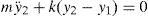
Based on fundamental vibration period perspective, an insight into the benefits of using base isolators in structures can be gained by considering the special case of a single-story linear undamped structure, which is separated from the ground by flexible bearings of lateral linear stiffness kb as shown in Fig. 1(a). The bearings are connected together through a base mass, which is a rigid horizontal diaphragm of mass mb just above the bearings. The whole system is idealized as a 2DOFs spring-mass system as shown in Fig. 1(b). The governing equations of motion are
where m is the main mass, k is the stiffness of the structure above the isolator and y1 and y2 are the total displacements of the base and the main masses, respectively. If the relative displacements between the masses and the supports are defined to be


It then follows from substituting Eq. (2) into Eq. (1) that


Consider the special case where mb is very small and so is assumed zero. Therefore, Eq. (3a) becomes
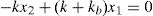
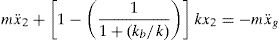
Solving for x1 in terms of x2 in Eq. (4) gives
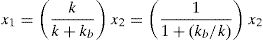
The displacement x1 is the displacement of the base isolator relative to the ground. Eq. (5) gives the value of x1 in terms of x2 and the ratio of the isolator stiffness to that of the structure. Note that if kb goes toward infinity (i.e. very stiff bearing), then x1 goes toward zero. In addition, if kb is equal to k, then x1 is equal to one-half of x2. The ideal, or perfect, isolation case is attained if kb goes toward zero. In this case, x1=x2 which translates into zero story drift, perfect rigid-body vibration of the structure and full structure-ground separation in the horizontal direction. Substituting Eq. (5) into Eq. (3b) gives the equation of motion for this spring-mass system as
One important effect of the presence of base isolators, seen in Eq. (6), is the modification of the natural frequency of vibration of the system. In this spring-mass system, the natural frequency of vibration is
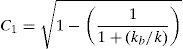
where ωn=k/m, and C1 is the base isolated natural frequency of vibration coefficient, defined as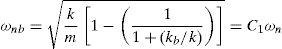
The natural period of vibration is
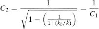
where Tn=2π/ωn, and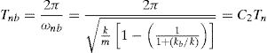
Insight into the meaning of a rigid, or fixed, base structure can be gained from Eq. (7). If kb is much greater than k1, then the term in the denominator, that is, 1+(kb/k), of Eq. (7) becomes large, and therefore ωnb approaches the natural frequency of a rigid base system k/m and Tnb approaches the natural period of vibration of a rigid base system 2π/k/m.
The situation of interest for a base isolated structure is the case where kb is less than k. In the limit if kb is very small, then ωnb goes to zero, see Eq. (7), and the natural period of vibration of the structure Tnb goes to infinity, see Eq. (9) which corresponds to the fully isolated condition. Eq. (5) can be rewritten to express the ratio x1/x2 as a function of the ratio kb/k. In this case, if kb/k becomes large, then x1/x2 tends to zero. This is the fixed base condition.
3Historical development of isolation systemsSeismic isolation is not a very new idea. More than a century ago, in 1885, John Milne, a professor of engineering in Japan, built a small wooden house on balls in cast-iron plates with saucer-like edges on the heads of piles, to demonstrate that a structure could be isolated from earthquake shaking [1]. However, the building behavior under wind loads was not satisfactory. Therefore, he reduced the balls diameter from 10inch to 1/4inch. By this mean, the building became stable against wind loads and was evidently successful under actual earthquake action. In 1891, after Narobi earthquake, a Japanese person, Kawai, proposed a base isolated structure with timber logs placed in several layers in the longitudinal and transverse direction [2].
In 1906, Jacob Bechtold of Germany applied for a U.S. patent in which a seismic-resistant building is to be placed on rigid plate supported on spherical bodies of hard material [3]. In 1909, a medical doctor from England, Calentarients, had submitted a patent application to the British patent office for a method of building construction. In his method, a building is constructed on a layer of fine sand, mica, or talc that would allow the building to slide in an earthquake, thereby reducing the force transmitted to the building itself [4]. In 1929, Robert de Montalk of New Zealand filed a patent application for an invention comprising a means whereby a bed is placed and retained between the base of a building and its solid foundation. The bed was being composed of material which will absorb or minimize seismic shocks [5].
There are almost a hundred known proposals for a seismic isolation systems made prior to 1960, but as far as can be determined, none were ever built. The most probable reason is a lack of practicality and the fact that the engineering profession of the day had little or no confidence in their success [3]. One notable historic structure, however, is Frank Lloyd Wright's Imperial Hotel in Tokyo, completed in 1921. This building was founded on a shallow layer of firm soil, which in turn was supported, by an underlying layer of mud. Cushioned from devastating ground motion, the hotel survived the 1923 Tokyo earthquake and later Wright wrote in his autography [6] of the “merciful provision” of 60–70 feet of soft mud below the upper 8 foot thick surface soil layer which supported the building. The imperial Hotel was an evidence that base isolation works and seismic protection can be achieved by relatively simple means.
Since the 1920s there have been other “accidents” in which some structures have survived earthquakes while neighboring buildings have collapsed. Several unreinforced masonry buildings were only lightly damaged in the 1933 Long Beach earthquake because they were able to slide on their grade beams. At least one masonry house survived the 1976 Tangshan earthquake because it also slid on its foundation inadvertently. Reconnaissance reports also describe instances of slender structures surviving earthquakes because of their ability to rock or side sway. Water tanks and statues, chandeliers and suspension bridges are some examples.
Attempts were made in the 1930s to protect the upper floors of multistory buildings by designing very flexible first-story columns. It was proposed that the first-story columns should be designed to yield during an earthquake to produce isolation and energy-absorbing actions. However, to produce enough damping, several inches of displacements is required, and a yielded column has greatly buckling loads, proving the concept impractical. To prevent the structure from moving too far, the first story is constructed underground and energy dissipators are installed at the top of this story [7]. To overcome the inherent dangers of soft supports at the base, many types of roller bearing systems have been proposed. The rollers and spherical bearings are very low in damping and have no inherent resistance to lateral loads, and therefore some other mechanisms that provide wind restraint and energy absorbing capacity are needed. A long duration between two successive earthquakes may result in the cold welding of bearings and plates, thus causing the system to become rigid after a time. Therefore, the application of the rolling supports was restricted to the isolation of special components of low or moderate weight [8].
Parallel to the development of the soft first-story approach, the flexibility of natural rubber was also seen to be another solution for increasing the flexibility of the system. The first use of a rubber isolation system to protect a structure from earthquakes was in 1969 for a three-story elementary school in Skopje, Republic of Macedonia. The building was constructed of reinforced concrete shear walls and supported by 54 large blocks of hard rubber. These rubber blocks were completely unreinforced, so the weight of the building causes them to bulge sideways. To improve the building stability under minor vibrations, glass blocks acting as seismic fuzes are intended to break when the seismic loading exceeds a certain threshold. Owing to having the same stiffness of the isolation system in all directions, the building bounces and rocks backwards and forwards [9]. These types of bearings are unsuitable for the earthquake protection of structures.
The subsequent development of laminated rubber bearings in 1970s has made seismic isolation a practical reality [10–12]. These bearings are very stiff in the vertical direction to carry the structural weight but are very flexible horizontally to enable the isolated structure to move laterally under strong ground motion. In the early 1980s, developments in rubber technology led to new rubber compounds, which were termed high damping rubber (HDR) [13]. Later, a large number of isolation devices were developed including rollers, springs, friction slip plates, capable suspension, sleeved piles, and rocking foundations. Now seismic isolation has reached the stage of gaining acceptance and replacing the conventional construction, at least for important structures.
It is not just the invention of the elastomeric bearing, which has made seismic isolation a practical reality. Three other parallel, but independent, developments have also contributed to its success. The first of these was the development of reliable software for the computer analysis of structures to predict their performance and determine design parameters. The second development was the use of shaking tables, which are able to simulate the effects of real recorded earthquake ground motions on different types of structures. A third important development is in the skill of the engineering seismologist in estimating ground motions at a particular site.
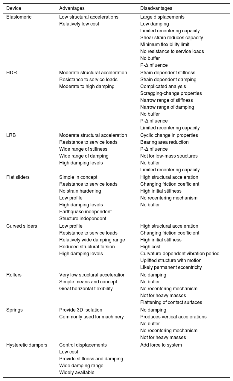
Table 1 summarizes the advantages and disadvantages of the most commonly used devices for seismic isolation. These advantages and disadvantages are brief, general and may not be comprehensive. Further, the listed disadvantages may apply to a generic type; some manufactures may have specific procedures to alleviate one or more of the disadvantages.
Advantages and disadvantages of commonly used isolation systems.
| Device | Advantages | Disadvantages |
|---|---|---|
| Elastomeric | Low structural accelerations | Large displacements |
| Relatively low cost | Low damping | |
| Limited recentering capacity | ||
| Shear strain reduces capacity | ||
| Minimum flexibility limit | ||
| No resistance to service loads | ||
| No buffer | ||
| P-Δinfluence | ||
| HDR | Moderate structural acceleration | Strain dependent stiffness |
| Resistance to service loads | Strain dependent damping | |
| Moderate to high damping | Complicated analysis | |
| Scragging-change properties | ||
| Narrow range of stiffness | ||
| Narrow range of damping | ||
| No buffer | ||
| P-Δinfluence | ||
| Limited recentering capacity | ||
| LRB | Moderate structural acceleration | Cyclic change in properties |
| Resistance to service loads | Bearing area reduction | |
| Wide range of stiffness | P-Δinfluence | |
| Wide range of damping | Not for low-mass structures | |
| High damping levels | No buffer | |
| Limited recentering capacity | ||
| Flat sliders | Simple in concept | High structural acceleration |
| Resistance to service loads | Changing friction coefficient | |
| No strain hardening | High initial stiffness | |
| Low profile | No recentering mechanism | |
| High damping levels | No buffer | |
| Earthquake independent | ||
| Structure independent | ||
| Curved sliders | Low profile | High structural acceleration |
| Resistance to service loads | Changing friction coefficient | |
| Relatively wide damping range | High initial stiffness | |
| Reduced structural torsion | High cost | |
| High damping levels | Curvature-dependent vibration period | |
| Uplifted structure with motion | ||
| Likely permanent eccentricity | ||
| Rollers | Very low structural acceleration | No damping |
| Simple means and concept | No buffer | |
| Great horizontal flexibility | No recentering mechanism | |
| Not for heavy masses | ||
| Flattening of contact surfaces | ||
| Springs | Provide 3D isolation | No damping |
| Commonly used for machinery | Produces vertical accelerations | |
| No buffer | ||
| No recentering mechanism | ||
| Not for heavy masses | ||
| Hysteretic dampers | Control displacements | Add force to system |
| Low cost | ||
| Provide stiffness and damping | ||
| Wide damping range | ||
| Widely available | ||
Rough inspection of Table 1 confirms the fact that each of the seismic isolation systems mentioned above has specific dynamic properties and functions but no device is perfect. This motivates the efforts either to enhance the existing devices or to innovate others with the aim of attaining the maximum protection level of structures through seismic isolation. Unfortunately, most of the isolation systems reported in the literature are patented products (the same is also true with most newly invented products), not all of them are readily available for procurement and direct enhancement. Therefore, the intention may be directed toward creating more efficient isolation devices. The next section presents for a case study using a novel seismic isolation system named Roll-in-Cage (RNC) isolator, which is an attempt that aims to combine the best features of the present day isolation systems, while avoiding their main drawbacks, in a single unit. Detailed numerical results are presented and discussed into the companion paper, Part II.
The Roll-in-Cage (RNC) isolator has been recently proposed, [14,15], as an attempt of enhancement, see Fig. 2. It is a rolling-based isolation system to achieve the maximum possible structure-ground decoupling, and therefore, to minimize the seismic force transfer to the isolated structure. It is designed to achieve a balance in controlling isolator displacement demands and structural accelerations. It provides in a single unit all the necessary functions of vertical rigid support, horizontal flexibility with enhanced stability, hysteretic energy dissipation and resistance to minor vibration loads. Although the rolling core is quasi-ellipsoidal, the RNC isolator generates no vertical fluctuation of isolated structure during motion due to the inner curvatures of the upper and lower bearing plates. Moreover, the RNC isolator is distinguished by three unique features: (1) a self-stopping (buffer) mechanism to limit the isolator displacement under severe seismic excitations, such as near-fault earthquakes, to a preset value by the structural designer; (2) a linear gravity-based self-recentering mechanism that prevents residual displacement after earthquakes (such recentering mechanism is a result of adopting a quasi-ellipsoidal shape of the rolling core); and (3) significant resistance to vertical axial tension provided by metallic yield dampers along its perimeter.
 full isometric view; (b) vertical half-sectional views; (c) three- dimensional partial sectional view.")
Besides the rolling-based motion mechanism, which requires less lateral forces to initiate and maintain high degree of structure-ground decoupling compared to other motion mechanisms of the elastomeric-based and friction-based isolation systems, the RNC isolator is provided with a consistent design of the lateral stiffness mechanism to get the most benefit of that rolling-based motion mechanism. Such design advantage lies in the independency of both vertical bearing mechanism and the mechanism that provides lateral pre-yield stiffness against minor vibration loads. This independency allows for accurate tuning of the initial pre-yield stiffness to permit the commencement of the seismic isolation process, or structure-ground decoupling, just after the seismic forces exceed the maximum limit of minor vibration loads, contrary to the available isolation systems. To support heavy and extra heavy structures, the RNC isolator is provided with a linear hollow elastomeric cylinder, with a designed thickness, around the rolling core to represent the main vertical load carrying capacity, while the rolling core itself works as a secondary support in this case. The RNC isolator can be available in different other forms to suit the structure or object to be protected. More detailed description and thorough treatment of the RNC isolator is found in reference [14].
4Seismic isolation of adjacent asymmetric buildings using the RNC isolator4.1IntroductionTorsion adversely affects the response of conventional structures, as well as seismic isolated structures. It was found that 42% of the collapses that occurred in Mexico City during the 1985 earthquake were related to the torsional response of asymmetric buildings [16]. Many of the buildings being constructed today display torsion effects when dynamically excited. These effects are clearly to be expected if the center of mass (CM) of the building is significantly offset from its center of rigidity (CR). In such a case the building's columns are subjected to loads arising from both translation and rotation of the overall building. The magnitude of the torsional responses with respect to the translational ones is governed by the participation factors of the relevant modes. Although the total inter-story shear forces in an eccentric structure can be reduced by the participation of torsional modes of vibration, the shear forces and displacements of any given column tend to increase as its distance from the structural center of rigidity increases. Over-stressing of structural components is therefore more likely in a building which has its CM offset from its CR than in one that does not. Practical problems such as material inhomogeneities precludes the construction of buildings with perfect coincident centers of mass and rigidity. For this reason alone, torsional effects would be present to some extent in all buildings.
As a consequence, for design purposes, it would be desirable to restrict such negative effects through minimizing or even eliminating of torsional responses of asymmetric structures [16–18]. Passive seismic isolation systems are devised to mitigate the destructive effects of earthquakes in buildings and their contents by controlling the seismic input. Practically, the effectiveness of seismic-isolated structures’ performance is strongly influenced by its torsional behavior. Almost all structures experience three-dimensional response during ground motions due to lack of symmetry between the structure's center of rigidity (CR) and center of mass (CM). One or more dominant lateral natural frequencies of the structure may tune with its torsional frequency [19]. Several researchers have investigated the coupled lateral-torsional response of fixed-base and seismic-isolated buildings [20–24]. Most investigations have found that coupling between translational with the rotational modes significantly affects the behavior of seismic-isolated structure and this effect needs to be rigorously considered in analysis and design.
Regarding the seismic behavior of asymmetric multi-story isolated structures, the available literature shows that the response of isolated asymmetric structures is still an ongoing research topic with relatively few works available. Some of the first reported research studies on simple rigid superstructure models could be found in [20,21] and on multi-story models in [25]. They have concluded that a seismic isolation system with zero or a small amount of eccentricity significantly reduces torsion in those systems caused by superstructure asymmetry. Using multi-story models, [23] concluded that the isolation system eccentricity as well as asymmetry and dynamic characteristics of the superstructure are both important generators of torsion in seismic isolated structures, nevertheless, that the torsional amplifications are reduced due to the isolation system. Similarly, [24] concluded that the base isolation system becomes less effective for greater eccentricities, since the displacements of the seismic isolation system are increased due to a larger contribution of torsion.
In reference [17], it was shown that the base displacement demand amplifications of an isolation system are big for large eccentricities of the asymmetric structure. This means that the asymmetry reduces the effectiveness of seismic isolation systems, since the more exposed isolators tend to deform plastically, while the others still remain elastic. In [18] the effect of a seismic isolation system eccentricity is studied even more in detail. It was concluded that a greater eccentricity of the seismic isolation system (the ratio between the eccentricity and the plan dimensions of the isolated structure is >15%) has an even more negative base displacements effect than the superstructure eccentricity and, therefore, an eccentric seismic isolation system should not be used in structural practice. In [16] it is pointed out that bigger torsional amplifications can be expected in the case of a mass eccentric structure than in the case of stiffness eccentric structures. Ref. [26] contrarily concludes that the eccentricity of the superstructure does not have a significant effect on the torsional amplifications of the base displacements. Additionally, for the torsionally flexible seismic isolation systems and smaller base eccentricities, the maximum amplification of the response occurs at the stiff edge. Otherwise, for torsionally stiff isolation systems, the maximum amplifications occur at the flexible edge.
Seismically isolated structures can experience large displacements at the isolation level during strong earthquake excitations, especially for long-period impulse near-fault ground motions. To simply accommodate such large displacements, a sufficiently wide clearance is provided around the structure to accommodate these large bearing deformations. However, the width of a chosen seismic gap is limited because of practical and architectural constraints and the associated cost especially in metropolitan areas. Therefore, seismic pounding between adjacent structures became a commonly observed phenomenon during major earthquakes. Pounding may cause both architectural as well as structural damages and, in some cases, it may lead to collapse of the whole structure. For example, the earthquake that struck Mexico City in 1985 showed that pounding was present in over 40% of 330 collapsed or severely damaged buildings surveyed, and in 15% of all cases it led to collapse, as reported by [27,28]. During the 1989 Loma Prieta earthquake, there were over 200 pounding occurrences involving more than 500 buildings [29].
Many investigations have been carried out on pounding damage caused by past earthquakes [30–33], on mitigation of pounding hazards [34–38], and on modeling of pounding between structures [39–45]. Pounding between adjacent structures is a very complex phenomenon, which may involve plastic deformation, local crushing as well as fracturing at the contact. These nonlinear deformations are not easy to be incorporated into the modeling of pounding. Therefore, idealizations and assumptions have inevitably been used in theoretical models [39–41,44]. For example, structures have been idealized as rigid barriers, single-degree-of-freedom oscillators or multi-degree-of-freedom oscillators; pounding between structures have been modeled by linear dashpot-spring system or nonlinear impact model. Despite of these simplifications, theoretical analyses have been valuable in providing insight into the pounding mechanisms [42,43,45]. Several recent research works have investigated different issues of structural pounding including modeling, mitigation and finite element investigation [46–50].
An experimental investigation into an effective relaxation method for reducing severe structural damage due to pounding was presented by [51]. They found that the force, acceleration and velocity produced by earthquake-induced structural pounding are remarkably mitigated by inserting a soft shock-absorbing material into the separation seismic gap. The effects of seismic pounding on the response of base-isolated reinforced concrete buildings under bidirectional excitation were investigated by [52]. It was found that considering unidirectional excitation instead of bidirectional excitation for near-fault motions provides highly unconservative estimates of superstructure demands. A sloped V-shaped multi-roller isolation system was proposed by [53] and experimentally verified to provide pounding prevention mechanism.
However, none of the above studies has reduced torsional responses of isolated asymmetric structures to a degree close to its entire elimination. This is because they all depend on seismic isolation systems having inherently dependent bearing and elastic stiffness mechanisms, which imposes serious limitations on tuning the isolator's elastic stiffness without affecting its bearing and damping mechanisms in addition to the dimensions of the isolation unit and consequently its overall behavior. Moreover, none of the above mentioned studies considered the potential of torsional pounding as the research in this area is still ongoing. Alternatively, this paper attempts to present another solution for significantly improving the seismic performance of asymmetric seismically-isolated buildings under sever near-fault (NF) earthquakes using the Roll-in-Cage (RNC) isolator [14,15,50,54–57]. Some of the most devastating earth- quakes are near-fault type. In general, the near-fault earthquake are nearly the most severe and destructive ground motions. The study considers minimizing, or even entirely eliminating, the torsional responses of RNC-isolated asymmetric buildings, besides prevention of their torsional pounding with adjacent structures under insufficient separation gaps with the surrounding adjacent structures. The main objective of this paper is the minimization/elimination of torsional responses of isolated buildings and its effect on their torsional pounding mitigation/elimination with closely spaced adjacent structures under near-fault earthquakes.
To minimize or prevent structural torsion of RNC-isolated structures, the RNC isolator has inherently independent bearing and pre-yield elastic stiffness mechanisms to allow for accurate and proper tuning of its elastic stiffness as required with no influence on its bearing mechanism nor on the resulting overall dimensions and behavior of the RNC isolator unit. To prevent seismic pounding of RNC-isolated asymmetric superstructure, the RNC isolator has an inherent self-stopping or buffer mechanism, which is able to draw down all the possible pounding of the superstructure downward to be inside the solid body of the RNC isolator. This buffer mechanism is activated if the peak bearing displacement exceeds a certain design displacement previously selected by the structural designer. For more information on the RNC isolator please refer to the above references by the authors. All studies are carried out using nonlinear time history analysis provided by the specialized computer code SAP2000 ([58]), as explained in details by [59]. It is to be emphasized that possible frictional pounding of asymmetric buildings with their closely spaced adjacent structures is not considered in this study. The reason is that the proposed methodology for minimizing or even eliminating torsion aims at forcing the asymmetric building to nearly behave as a symmetric building exhibiting no twist around a vertical axis, which is the only source of frictional pounding. Accordingly, the likely frictional pounding is assumed negligible until achieving the objectives of this paper without negatively influencing its scope.
4.2Asymmetric building structure consideredFig. 3 shows a schematic diagram of the RNC-isolated linear ten-story asymmetric structure, which is surrounded with a fixed-base rigid L-shaped adjacent structure for this study. The adjacent structure is assumed to be fixed-base and rigid non-deformable body to focus mainly on the effects of the proposed approach on the asymmetric structure itself under consideration. In addition, such selection of that adjacent structure represents a virtual vertical surrounding limits that must not be exceeded by the RNC-isolated asymmetric structure under consideration in order to approach a realistic case of study in metropolitan near-fault zones. The L-shape of the adjacent rigid structure, of the same height, is chosen to consider possible simultaneous pounding in X and Y directions. The structure is an asymmetric 3D building of 5 bays, each of 8.0m span, with outer end cantilevers of 2.5m length in both horizontal directions. It has 10 floors besides the isolated base floor with a typical story height of 3.0m. The horizontal structure's eccentricities between the centers of mass (CM) and rigidity (CR) are 2.5098m and 0.9020m in X and Y directions and are referred to as ex and ey, respectively. Those eccentricities are equivalent to 12.55% and 4.50% of half the in-plan structural dimensions in X and Y directions, respectively. The base isolated building is modeled as a shear type structure supported on 36 heavy-load RNC isolators, [50], one under each column. Each floor has two lateral displacement degrees of freedom (DOF) beside one rotational DOF around the vertical axis. The structure is excited by uni- and bidirectional horizontal earthquake components XX and YY directions.

The superstructure is assumed to remain elastic during the earthquake excitation and impact phenomenon. The construction material of the isolated structure is normal-weight reinforced concrete with a total material volume of 3738.40m3 and the structure has a total weight of 93,460.0kN. The structural foundation is assumed rigid and supported on rocky soil. The fixed-base structure has a fundamental period of 0.47696s, while the first twenty natural modes of vibration are considered in the analysis. The structural damping ratio for all modes is fixed to 2.50% of the critical damping, [60,61]. The reason of using a low fundamental period in this study is to get the isolated superstructure more affected by the ground accelerations besides the contained displacements and velocity pulses in the near-fault ground motions. The intention is to investigate the proposed RNC isolator in these challenging loading conditions.
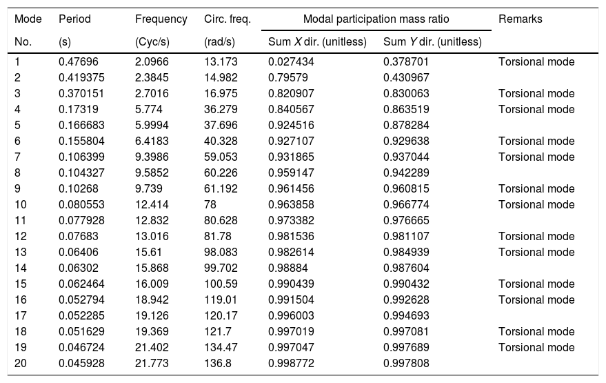
All studies are carried out in this paper using nonlinear time history analysis. Particularly, by using the method of fast nonlinear analysis of SAP2000, which is a modal time history analysis based on load-dependent Ritz vectors. The number of structural vibration modes included in the analysis are 20 modes. This number of modes was selected to achieve static modal load participation ratios of 100% in both X and Y directions, in addition to dynamic modal load participation ratios of 100% in X and Y directions too. Moreover, this number of modes was found necessary to entirely and properly capture the localized high frequency responses in the nonlinear link elements due to seismic pounding. Table 2 lists the main characteristics of those 20 considered vibration modes of the fixed-base asymmetric structure. The table shows that the majority of the natural vibration modes (13 modes out of 20) of the considered structure are torsional modes. To make sure that the drawn conclusions are not biased by analysis assumptions, some spot results are later checked using the time-consuming direct integration nonlinear time history analysis.
Main characteristics of the considered 20 natural vibration modes of the fixed-base asymmetric structure.
| Mode | Period | Frequency | Circ. freq. | Modal participation mass ratio | Remarks | |
|---|---|---|---|---|---|---|
| No. | (s) | (Cyc/s) | (rad/s) | Sum X dir. (unitless) | Sum Y dir. (unitless) | |
| 1 | 0.47696 | 2.0966 | 13.173 | 0.027434 | 0.378701 | Torsional mode |
| 2 | 0.419375 | 2.3845 | 14.982 | 0.79579 | 0.430967 | |
| 3 | 0.370151 | 2.7016 | 16.975 | 0.820907 | 0.830063 | Torsional mode |
| 4 | 0.17319 | 5.774 | 36.279 | 0.840567 | 0.863519 | Torsional mode |
| 5 | 0.166683 | 5.9994 | 37.696 | 0.924516 | 0.878284 | |
| 6 | 0.155804 | 6.4183 | 40.328 | 0.927107 | 0.929638 | Torsional mode |
| 7 | 0.106399 | 9.3986 | 59.053 | 0.931865 | 0.937044 | Torsional mode |
| 8 | 0.104327 | 9.5852 | 60.226 | 0.959147 | 0.942289 | |
| 9 | 0.10268 | 9.739 | 61.192 | 0.961456 | 0.960815 | Torsional mode |
| 10 | 0.080553 | 12.414 | 78 | 0.963858 | 0.966774 | Torsional mode |
| 11 | 0.077928 | 12.832 | 80.628 | 0.973382 | 0.976665 | |
| 12 | 0.07683 | 13.016 | 81.78 | 0.981536 | 0.981107 | Torsional mode |
| 13 | 0.06406 | 15.61 | 98.083 | 0.982614 | 0.984939 | Torsional mode |
| 14 | 0.06302 | 15.868 | 99.702 | 0.98884 | 0.987604 | |
| 15 | 0.062464 | 16.009 | 100.59 | 0.990439 | 0.990432 | Torsional mode |
| 16 | 0.052794 | 18.942 | 119.01 | 0.991504 | 0.992628 | Torsional mode |
| 17 | 0.052285 | 19.126 | 120.17 | 0.996003 | 0.994693 | |
| 18 | 0.051629 | 19.369 | 121.7 | 0.997019 | 0.997081 | Torsional mode |
| 19 | 0.046724 | 21.402 | 134.47 | 0.997047 | 0.997689 | Torsional mode |
| 20 | 0.045928 | 21.773 | 136.8 | 0.998772 | 0.997808 | |
Several RNC isolators are designed for this study. For example, one design is able to accommodate a travel design displacement, xdes, of 650mm without losing its restoring capability. Just after exceeding that selected xdes, the self-stopping (buffer) mechanism is directly activated to stop motion over a stopping distance xbrake. The stopping distance depends mainly on pounding force intensity, FbB, and the selected buffer stiffness kb. That designed RNC isolator example is 1.35m high. The outer diameter of the upper and lower bearing steel plates is 2.43m. It is provided with 16 hysteretic mild steel dampers, [50], each has a diameter of 40mm. To enable adequate vertical load capacity, the RNC isolator is provided with a linear hollow elastomeric cylinder around the rolling core to represent the main vertical load carrying capacity, while the rolling core itself works as a secondary vertical support in this case. The inner and outer diameters of the hollow elastomeric cylinder are 1.73m and 2.33m, respectively. This linear elastomeric part was initially designed to follow some available recommendations of the Uniform Building Code, [62], and AASHTO, [63], to provide a minimum vertical load capacity of 4000.0kN at the extreme deformed position of buffer and to provide several times that capacity at neutral or less deformed positions.
4.4Gap element modelThe direct seismic pounding of RNC-isolated asymmetric structure and the inner pounding of the RNC isolator are modeled using a Link/Support property of SAP2000 named the Gap element or “compression-only” property. The Gap element can be assigned to any deformational degree of freedom independently. Fig. 4 demonstrates the main components and connectivity of the Gap element in case of being used to model seismic pounding of the superstructure, as shown in Fig. 4(a), and to model the inner pounding of the RNC isolator, as shown in Fig. 4(b). The nonlinear force-deformation relationship of the Gap element is given by:
where k is the spring constant, and “open” is the initial gap opening, which must be zero or positive.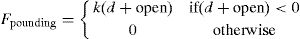
 A Gap element to model seismic pounding of superstructure; (b) A Gap element to model the RNC isolator")
The inner RNC isolator's pounding as well as the seismic pounding of the RNC-isolated asymmetric structure are simulated using the gap elements. The gap elements representing RNC isolator pounding are located horizontally at the isolation level, while those gap elements representing structural pounding are placed horizontally at the topmost shared edges and corners between the RNC-isolated structure and the adjacent structure, as demonstrated by Fig. 3. There are two main limitations of using the gap elements shown in Fig. 4. The first limitation is their unidirectional behavior. This difficulty was completely overcome in this paper to account for spatial collisions at the horizontal isolation plan and the topmost floors of the RNC-isolated and adjacent structures. Accordingly, two perpendicular gap elements are assigned to each RNC isolator (one along X and the other along Y directions). Similarly, another two identical and perpendicular sets of gap elements are used in X and Y directions to capture spatial structural pounding with adjacent structure, see the top most structural floors in Fig. 3. Moreover, both ends of each gap element are not restrained against spatial rotations. This allows the perpendicular gap elements to entirely capture any spatial pounding forces that are not central or collinear with the gap elements. The other limitation of the gap elements lies in their inability to model damping. Therefore, collision damping was conservatively neglected from the numerical simulation models, including structural and inner RNC isolator impact forces. Therefore, the proposed approach is conservative and is valid as long as the collision damping is relatively small and could be ignored, as was assumed in this paper. To approach a rigid behavior of the RNC isolator's buffer, its biaxial lateral stiffness is chosen as 2.50×10⁶kN/m. Similarly, the bidirectional lateral stiffness of the adjacent rigid structure is taken as 2.50×10⁶kN/m for the same reason.
4.5RNC isolator's buffer mechanismFig. 5 shows a RNC isolator design, for light to moderate weight structures, at neutral and maximum deformed positions together with the corresponding force–displacement relationship in each case. The force–displacement relationships shown in Fig. 5 are idealizations of those obtained using both numerical and experimental studies [64]. Different components of the RNC isolator are configured to provide a built-in buffer mechanism. The upper and lower bearing plates have vertical right angle edge-walls, along their outer perimeters, to conform to two corresponding right-angle grooves that are cut in the rolling core’ solid body. Both right-angle edge-walls and grooves constitute a stiff lock mechanism after a certain design displacement, xdes, that are specified by the structural designer, as shown in Figs. 5(a and c).
 to-the-left maximum deformed position; (b) neutral position; and (c) to-the-right maximum deformed position.")
The rigid rolling core can work as a rigid link member in compression between the upper and lower bearing plates to stop the isolator motion at this point within a small braking distance. Such braking distance depends mainly on the shock severity and the lateral stiffness of the edge-walls of the bearing plates. The weight of the isolated shear structure prevents the rolling core from stepping over the vertical edge-walls. The buffer mechanism aims at preventing uncontrolled isolator displacement and to maintain the isolated structure stability under earthquakes stronger than a design earthquake. In addition, it could be particularly useful in avoiding direct pounding of RNC-isolated structures with surrounding adjacent structures in case of limited seismic gaps especially under severe ground motions, which is the main objective of this paper, since pounding (if any) will take place only within the solid metallic body of the RNC isolator.
Probably it is worth explaining the behavior of the RNC isolator just after exceeding a certain horizontal design displacement xdes, according to Fig. 5. The integrated buffer has a unique stiffness kB, which is always higher than the dampers stiffness. The kB is activated only after exceeding the design displacement and it is represented with the steeper slope in Fig. 5 in the first and the third quadrants. The activation of the buffer stiffness means deactivation of the dampers stiffness and conversely. The less steep slope is attributed to the less stiff metallic yield dampers, which are reactivated again when the buffer mechanism becomes deactivated as the RNC isolator reaches the end of stroke and start to reverse its direction of motion.
The followed strategy in this paper to minimize or eliminate torsional responses of RNC-isolated asymmetric structures is explained in details in the companion paper, Part II, while the strategy of seismic pounding elimination of the RNC-isolated superstructure is schematically explained in Fig. 6. According to Fig. 6, the seismic gap between a RNC-isolated structure and a surrounding adjacent structure is chosen to be a little bigger than the sum of the RNC isolator's design displacement and the peak fixed-base structural drift, as shown in Fig. 6(a). During severe ground shaking, as shown in Fig. 6(b), the peak bearing displacement is limited to the previously chosen design displacement, while the remaining of the seismic gap could account for the peak structural drift. Since there is often a limit for seismic gaps, the structural designer could design the RNC isolator to always prevent direct seismic pounding of the RNC-isolated superstructure with closely spaced surrounding adjacent structures in two different ways. The first way is to permit inner pounding of the RNC isolator (if the amplified structural responses due to that inner pounding are within acceptable limits), while the second way is to entirely avoid the inner RNC isolator's pounding by means of choosing more appropriate characteristics of the RNC isolator.
4.6Equations of motion
The following assumptions applies to the structural system under consideration: (1) the superstructure remains within the elastic limit during the earthquake excitation and the non- linearity is concentrated only at the isolation elements; (2) the floors are assumed rigid in its own plane; (3) the structural columns are inextensible vertically providing the lateral stiffness of the structure; (4) the effects of soil-structure interaction are neglected. The equations of motion for fixed-base structure under earthquake ground acceleration are expressed as
where Ms, Cs and Ks are the mass, damping, and stiffness matrices of the superstructure, respectively; xs={x1, x2,.., xN}T, x˙s and x¨s the unknown relative floor displacement, velocity and acceleration vectors, respectively; vector of influence coefficients; x¨g is the earthquake ground acceleration; and r is the vector of influence coefficients.
In the case of isolated structure, Eq. (12) becomes
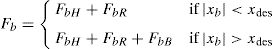
where x¨b is the relative acceleration of the base mass. The corresponding equation of motion for the base mass under earthquake ground acceleration is expressed bywhere mb and Fb are the base mass and the restoring force developed in the isolation system, respectively; c1 and k1 are the first story damping and stiffness, respectively; and η is the number of isolators. The overall restoring force, Fb, of the RNC isolator is expressed as follows:where xb is the horizontal displacement of the isolator or the base mass relative to the ground; FbH is the hysteretic restoring force component; FbR is the recentering restoring force component; and FbB is the buffer restoring force component of the RNC isolator. The hysteretic restoring force component, FbH, of the RNC isolator is adequately simulated mathematically by the standard form of the Bouc–Wen model of smooth hysteresis [65–67] as:where x is the displacement, z is an auxiliary variable, FbH is the isolator restoring force due to hysteretic yield dampers, αkx is the elastic force component, z˙ denotes the time derivative, n>1 is a parameter that governs the smoothness of the transition from elastic to plastic response (yielding exponent), Dy>0 is the yield constant displacement and 0<α<1 represents the post to pre-yielding stiffness ratio (kp/ke), while A, β and γ are non-dimensional parameters that govern the shape and size of the hysteresis loop.


The total recentering restoring force, FbR, of the RNC isolator is expressed mathematically as:
where xr is the relative-to-ground horizontal displacement of the ellipsoidal rolling core's center of gravity; θr is the rotation angle of the rolling core; xb is the horizontal displacement of the isolator or the base mass relative to the ground; mr and Jr are the mass and the moment of inertia of the rolling core; x¨g is the ground acceleration; Ws is the structural weight; mr and Wr are the mass and weight of the rolling core; expression p=a sin θ sin θr+b cos θ cos θr is half the vertical distance between the lower and upper contact points of the rolling core with upper and lower bearing plates, respectively; c=a sin θ cos θr–b cos θ sin θr is half the horizontal distance between the upper and lower contact points; a and b are the major horizontal and minor vertical radii of the ellipsoidal rolling core; θ is the eccentric angle. More on full mathematical modeling of the RNC isolator is found in Ref. [57].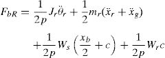
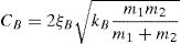
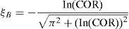
To express mathematically the third component of the restoring force caused by buffer, FbB, two cases have to be considered: (1) the isolator, or the isolated base, displacement xb due to ground motion excitation is less than the design displacement xdes. In this case, the restoring buffer force component FbB is set to zero; (2) the isolator displacement exceeds the previously set design displacement xdes, the buffer restoring force FbB becomes nonzero and is proportional to the buffer stiffness kB and the amount of xb beyond xdes. A force-based impact model is used to model the buffer damping, assuming an impact spring and an impact damper exerting, in parallel, impact forces to the colliding RNC isolator's elements whenever the design distances are exceeded. In particular, when a contact is detected, the RNC isolator's impact restoring force component FbB is estimated at each time step using the following formulas:
where δ(t) is the interpenetration depth (xb(t)–xdes), δ˙(t) is the relative velocity between the colliding bodies, kB is the buffer spring's stiffness and cB is the buffer impact damping coefficient. The latter is computed according to the following formulas, provided by [31], and based on the conservation of energy before and after impact:where m1, m2 are the masses of the two bodies, which are the superstructure above the RNC isolator and the foundation substructure below the RNC isolator; and COR is the coefficient of restitution, which is defined as the ratio of relative velocities after and before impact (0<COR≤1), [33,68].4.7Near-fault earthquakes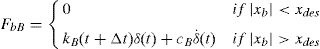
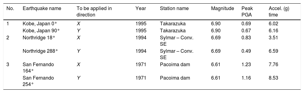
Near-fault (NF) earthquakes’ ground motion are characterized by one or more intense long-period velocity and displacement pulses that can lead to a large isolator displacement, [69,70]. Therefore, three pairs of NF ground motions having different intensities, velocity and displacement pulses are considered to evaluate the performance of the RNC isolator's self-stopping (buffer) mechanism. These pairs of NF ground motions are oriented in directions normal and parallel to the fault, where they were obtained from the near-most stations to the their fault rupture, with intensities that range from 0.27g to 1.23g to represent relatively low to severe intensity NF earthquakes. The peak ground accelerations (PGA), velocities (PGV) and displacements (PGD) against their corresponding time instants of each ground motion are listed in Table 3. On measuring the intensity of NF ground motions, [71] revealed that, the peak ground acceleration is a better representative intensity measure than the peak ground velocity. Accordingly, the used NF ground motions are sorted by their PGA in an ascending order.
Main characteristics of the NF ground motions used in this study.
| No. | Earthquake name | To be applied in direction | Year | Station name | Magnitude | Peak PGA | Accel. (g) time |
|---|---|---|---|---|---|---|---|
| 1 | Kobe, Japan 0° | X | 1995 | Takarazuka | 6.90 | 0.69 | 6.02 |
| Kobe, Japan 90° | Y | 1995 | Takarazuka | 6.90 | 0.67 | 6.16 | |
| 2 | Northridge 18° | X | 1994 | Sylmar – Conv. SE | 6.69 | 0.83 | 3.51 |
| Northridge 288° | Y | 1994 | Sylmar – Conv. SE | 6.69 | 0.49 | 6.59 | |
| 3 | San Fernando 164° | X | 1971 | Pacoima dam | 6.61 | 1.23 | 7.76 |
| San Fernando 254° | Y | 1971 | Pacoima dam | 6.61 | 1.16 | 8.53 |
Another measure of the ground motion characteristics is through comparing their response spectra. Fig. 7 compares the acceleration, velocity and displacement response spectra of the used three NF ground motions as well as the mean spectrum in each case. Figs. 7(a and b) justify the selection of an example structure with a fundamental period less than 0.50s. Such selection produces high structural responses under the three NF earthquakes because of high spectral accelerations and velocities within that zone. This provides a challenging situation to examine the proposed solution of response improvement using the RNC isolator.

In the companion paper, Part II, the dynamic behavior improvement of RNC-isolated asymmetric structures is presented. Detailed numerical results are explained and discussed.
5Summary and conclusionsThis paper is the first of two companion papers. It first introduces the seismic isolation concept, development history and compares available (most widely used) seismic isolation systems, highlighting their advantages and disadvantages. Next, it motivates the need for continuous improvement of seismic isolation systems to attain (economic) high protection levels (against seismic hazards) simultaneously with minimizing possibly arising drawbacks or side effects. Then, the paper presents a recently proposed seismic isolation device named Roll-in-Cage (RNC) isolator, as an example of improvement, which combines several desired mechanisms into a single unit. The second companion paper, Part II, addresses the possibility of eliminating, or at least minimizing, the torsional responses of isolated asymmetric structures using the RNC isolator considering near-fault (NF) ground motions. Introduction of such case study is presented in the present paper, Part I.