


The main aim of this work is to propose an alternative beam-to-column joint for use in building structures. This novel solution consists of a group of headed studs, and has been conceived to connect reinforced concrete floors to steel columns. It is a primary structural joint and it can be used both in conventional concrete beams and in slabs. The alternative approach presented in this work offers significant benefits compared to conventional joints. Some of these advantages are regarding simplicity, industrialization possibilities, shear strength capacity, as well as the excellent weld safety due to the use of headed studs.
El objetivo principal de este trabajo consiste en proponer una alternativa más económica y viable para las uniones entre forjados de hormigón y pilares metálicos. La solución que se propone en este trabajo consiste en un grupo de pernos conectores destinados a transferir las solicitaciones desde los forjados de hormigón hasta los pilares metálicos; consiste en una unión primaria, que es válida tanto para vigas de hormigón como para losas, y que aporta numerosas ventajas respecto a las uniones habituales, entre las que destacan la simplicidad, la posibilidad de industrialización, la seguridad y la alta capacidad de transmisión de cortante.
The beam-to-column joints proposed are thought to be primary shear studs connections and they can be used both in conventional concrete floors and in slabs [1,2].
The alternative approach presented in this work offer significant benefits regarding simplicity, industrialization possibilities, safety and shear strength capacity, compared to conventional joints [3].
At present, the most common solution used in building structures consists of a joint made up with two UPN steel profiles welded to the columns. In this way, the control and supervision of welding proceeding become essential to achieve the adequate safety levels [4,5].
This steel profiles connection has several disadvantages, mainly due to its cost-safety relationship.
2A joint-to-column joint proposalA new design of beam-to-column join has been carried out. For this purpose, the numerous advantages of headed studs have been harnessed. The geometry shape of the headed studs provides high capacity in shear loads transfer. Furthermore, they offer high tensile strength in anchors. The main advantages of headed studs are their high safety properties and the great strength provided from the electric arc welding process [6].
Fig. 1 shows an alternative beam-to-column connection conceived for a continuous reinforced concrete beam of building structures.
2.1Joint specifications
This beam-to-column joint is composed of a minimum of four headed studs for each side on which the shear is transmitted from the beam to the column. The dimension of the studs should not be less than 16mm diameter and 125mm length, in order to guarantee the minimum European requirements [7].
The horizontal reinforcement Ah represented in Fig. 1 has been mainly designed for the “breakout failure mode”. This is a typical break mode that is well known in anchors. It occurs due to proximity to a free edge when the concrete strength is exceeded.
The reinforcement Ac that surrounds the shear studs in Fig. 1 has been designed for the “pry-out failure mode”.
These both failure modes are well known in anchors and they are incorporated in American construction codes [8].
In this joint the headed stud has been allocated to transfer the shear loads from the beam (or from the slab) to the column
3Finite elements analysisThis paper presents a Ansys 3-D simulation by finite element method (FEM) of beam-to-column structural joint by headed studs.
The most unfavorable conditions to the mechanical behavior of these joints have been applied to get a greater convenience and a lower failure load in laboratory tests. Examples of these unfavorable conditions are the discontinuity of the reinforcement concrete through the joint, the absence of embedded of the steel column into the concrete beam, the lack of continuity of the concrete beam across the joint, the low number and sizes of headed studs, etc.
The headed stud size, Ф10100, has been selected based on smaller cross section commercially available. These headed studs had dimensions dp1=10mm diameter and lp1=100mm length. Manufacturing the joint with these studs provide lowest load capacity and will better performance laboratory tests.
It should be noted the shear capacity of these composite joints due to the failure of the steel studs is not limited by the strain values obtained in numerical analysis of Ansys model. The maximum load that the joint is able to support is limited by the shear strength of the steel inside the cross area of the headed studs, and it can be directly determined by formulation (1):
V_R = gamma·n·A_n·f_u
In this formula, the value is a reduction factor which correspond to 0.75 and 0.64 according to [8] and [7], respectively; n is the number of shear studs; An is the cross area; and fu is the ultimate tensile strength in steel studs (450MPa).
3.1FEM model detailsAs previously mentioned, the mechanical behavior of the beam-to-column structural joints has been simulated by the commercial program Ansys. The model has been built up from the simplification of the composite joint represented in Figure 2.

The steel in headed studs has been modeled with Solid-285 Ansys element. A linear, elastic and isotropic material has been used for these objects, with a Young modulus of Es=210GPa and a Poisson coefficient of ν=0.3.
Concrete beam has been simulated with the Solid-65. This element is defined by eight nodes, having three degrees of freedom at each node: translations in the nodal x, y, and z directions. Furthermore, this solid is capable of cracking in tension and crushing in compression.
In order to simulate the mechanic behavior of concrete in non-cracking steps, a Young modulus of Ec=20GPa have been applied. The Poisson's coefficient has been assumed to be V=0.2. In these first steps, the concrete is under elastic deformations.
Ansys typically simulate an ideal full link between together nodes. However, it is possible applying two reduction factors to simulate the decreasing in shear transfer capacity that occurs during the cracking processes. This shear reduction produces that a finite slip occurs across the fracture surface. One of these coefficients is for open cracks and the other one is designated for closed cracks, both of them must be included in the range 0<β≤1. In this work, a standard concrete has been simulated with βt=0.4 and βc=0.4.
On the other hand, the cracking in concrete is estimated modifying the stress–strain constitutive equations of the material during the process of cracking, and this cracking generates the fracture surfaces. In order to study the cracking behavior across this beam-to-column joint, the concrete has been defined by five Willam and Warnke parameters [9].
The first one is the compressive strength fck and it has been assumed as 25MPa because it is the resistance of concrete that is usually used in building structures. The second one is the tensile strength ft and it has been taken as fck2/3=2.5MPa according to the Spanish building rules, EHE [10].
The ultimate biaxial compressive strength fcb has been assumed as fcd according to [4] and the uniaxial and biaxial compressive strength superimposed on hydrostatic stress state, f1 and f2, has been taken as 1.45fck and 1.725fck, respectively, according to Ansys documentation of nonlinear materials.
Model has been meshed with variable sizes tetrahedral elements for each two materials, steel and concrete. The lower meshing sizes have been applied around the head stud welds. However, a higher nodes separation has been used for the areas further away of welds.
In order to reduce the computational costs a symmetrical model has been built. FE model is composed of a quarter of HEB-140 steel column; two headed studs; one half concrete beam with a symmetrical reinforced bars into the concrete.
Regarding the boundary conditions, vertical translations have been restricted on the upper and lower horizontal surfaces of the column. Obviously, all translations in the perpendicular direction to the symmetric planes have been restricted.
The vertical translations of the reinforced bars points located on the cross sections on the symmetrical central plane have not been restricted in order to ensure that shear loads will be fully conveyed through the headed studs.
Finally, the load has been defined introducing vertical translations instead of local forces because, in this way, a model with lower convergence problems is obtained. These translations are imposed on the cross-section further away from the welds.
3.1.1FEM analysis resultsMost relevant results achieved in this FEM simulation are the load capacity of 61kN, and the concrete breakout failure mode located at the upper headed stud. Figure 3 shows the graphical results obtained in this model.
3.2Experimental test Vertical deformation; b) Maximum longitudinal tension; c) Cracked concrete.")
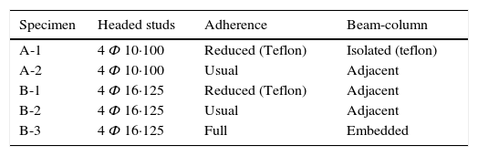
A total of five full-scale experimental tests have been developed at the Institute of Building Sciences Eduardo Torroja from the Spanish National Research Council, CSIC.
Two of these experiments (A specimens) have been carried out with the same configuration, unfavorable conditions and dimensions of models studied with FE simulations.
In order to minimize the friction effects between the concrete beam and the steel column, a teflon sheet has been embedded in the contact surface of both materials of one of the A specimens. In this way, it could be possible to evaluate the contribution of the shear capacity of the joint that is due to the adherence between the concrete and the steel.
Three additional tests (B specimens) have been performed in joints without many of the unfavorable conditions applied in previous models. In this way, more similar results to the real mechanical behavior in building structures is obtained and studied.
B specimens have been manufactured with a greater diameter (16mm) and with a progressive high steel reinforcement Ah and Ac, and B-2 and B-3 without teflon. Finally, B-3 specimen has been manufactured with the steel profile embedded into the concrete beam, in this way the most similar conditions to a real building structures joint have been included. Table 1 summarizes the tested specimens.
The materials and dimensions of each element which configure the specimen tests are the same previously used in theoretical study of FEM models. Their specific characteristics are described below.
The columns used in specimen tests were steel profiles HEB-140, manufactured with S-235JR.
Headed studs were Köko, fabricated with St-37.3K steel, and they were automatically welded by electric arc on the outer flange of columns. This stud type is guaranteed with a minimum tensile strength of 450MPa.
Concrete beams were manufactured with HA25/B/20/I concrete, and the average 28 day strength of the dry-cured concrete cylinders was 27.6MPa. Reinforcement bars were manufactured with B-500S steel.
The experimental tests (three A specimens and two B specimens) of beam-to-column joints have been performed with the same layout as three points flexion test of a beam. On the extreme side of each concrete beams has been incorporated a beam-to-column joint. In this way, half the load (because the load point is centered between both supports) is equivalent to the shear load which is transferred by the joint.
The global deformation values were obtained with vertical and horizontal translations transducer, as can be observed in Fig. 4. Thus, an internal instrumentation was applied. Several strain gauges were incorporated to instrument the headed studs and reinforcement bars (only the nearest ones to the joint), in order to obtain the stress levels of these both element types. Figure 4 shows how the support is aligned with the outer flange of column. In this way, the reaction force must be transferred through headed studs.
3.2.2Results
The experimental shear capacity results of A and B specimens are summarized in Table 2.
4DiscussionThe joint proposed in this paper is conceived to housing building composed by concrete beams and steel columns. The structures of these buildings are characterized by short beams length (from 3 to 5.5m approximately) and low living loads (from 9 to 10.5kN/m2).
In these structures, the values of shear loads in nodes are usually between to 65kN to 140kN approximately.
The shear capacity experimentally obtained in B specimens, in which only four studs with the smaller dimensions allowed by European structures codes (16mm diameter) are used, proves that beam-to-column joint by headed studs presented in this work is easy able to support the typical shear loads of more habitual structures of residential and similar buildings.
4.1Adherence and frictionThe results obtained in experimental tests in A1, A2, B1 and B2 specimens prove that a fraction of the shear is transmitted through the joint by friction [11]. This shows that friction plays a significant role in shear transmission. Comparing the shear strength values between the specimens in which the adherence has been reduced surrounding the steel profiles with teflon (A1 and B1 specimens) with the specimens without Teflon (A2 and B2), can be observed that a percentage of 6% and 8% of shear is transmitted by friction to the column.
The result of the laboratory test done with the B-3 specimen, in which the steel profile were embedded inside the concrete beam, proves the so high percentage of shear loads can be transmitted by adherence and friction from the beam to the column. In this experimental test the joint capacity highly overcame the predicted load. The failure of the specimen was due to exceed the bending capacity of the column profile.
It should be noted that this joint has been able to support the 350% of the maximal shear load that could be present in the structural building for this joint has been designed for.
4.2Results comparison between FEM and experimental testsThe comparison between experimental results with FEM simulations show that the failure mode obtained in laboratory tests are in agreement with the predicted by Ansys. In this way, FEM results prove that Ansys correctly simulate the concrete cracking in these structural joints and it is possible to reproduce its mechanical behavior until failure occurs.
However, the breaking load in experimental tests has proved to be higher than anticipated in numerical simulations (Fig. 5).

On the left of Fig. 6 the A-2 specimen is represented and the failure mode can be observed. It can be observed the breakout failure mode.

On the right, the Ansys simulation has been superposed. The area with red color is the fracture surface, built from the cracked concrete elements (Fig. 5).
In case the load capacity of the joint were limited by the shear strength of the steel of the headed studs, the maximum load never could the value of VR, that can be estimated by Eq. (1). According to European codes, than are more restrictive than American codes in this field, the ultimate shear strength due to the failure of the studs of A and B specimens are 90.5kN and 231.5kN respective.
Table 2 shows that A-2 specimen got a shear strength capacity lower than estimated by Eq. (1) and the collapse were due the steel failure of the shear studs. This proves how important the concrete contribution is in the mechanical behavior of the joint and how significant it is for the load capacity prediction.
5ConclusionsThe results obtained in experimental tests have confirmed the failure modes previously predicted by numerical models. However, generally the shear capacities obtained in experimental tests are significantly higher than expected by numerical models. This phenomenon is due to the effect of the reinforcement bars and also because a significant percentage of shear is transmitted from the beam to the column by adherence and friction.
The novel beam-to-column joint proposed in this paper are thought to be primary shear studs connections and it can be used both in conventional concrete floors and in slabs.
The alternative approach presented in this work offer significant benefits regarding simplicity, industrialization possibilities, safety and shear strength capacity, compared to conventional joints.