


Safety is the most important factor when developing software for safety-critical systems. Traditional approaches attempted to achieve safety through testing the software. However, there might be some bugs in the software not revealed in the test procedure. Formal verification is a new trend in developing safe software. In this paper, we propose a multi-phase formal approach for safety management in safety-critical software. We use timed transition Petri-net as a formal means to specify the properties of the model and their relations in each component of the software. In addition, we use the Z language to specify textual and mathematical specifications of the model, as a representative model to evaluate the proposed approach; we chose continuous infusion insulin pump (CIIP).
Computers play a significant role in operating many modern systems some of which are classified as safety-critical. Any failure in safety-critical systems may result in loss of life or significant damage to the environment. Examples include medical systems, aircraft flight control systems, weapons and nuclear systems. When designing such systems, which usually include both software and hardware, the most important factor is safety. In this paper, we focus on the design of safety-critical software.
The main approaches to improve the safety are divided into three classes: Theorem proving [1], model checking [2] and runtime verification [3]. Current safety paradigms usually use one of the aforementioned approaches or a combination of them. For example, runtime reflection [3] employs runtime verification and the approach proposed in [4] uses a combination of theorem proving and model checking. Safety approaches like timed automata [5] and Event-B [6] usually use formal methods to specify the system requirements or monitor the system behavior. Formal languages such as Z [7], is usually used to specify the system. For example, the approach proposed in [8] uses a combination of Petri-net and the Z language to verify medical software.
However, the main issue with current approaches is that they are not taking into consideration all safety angles. We believe safety must be observed in all software production phases. Therefore, we propose a formal approach which takes into account all software production phases including planning, requirements specification, designing, and implementation [9]. We explain the proposed approach step by step using continuous infusion insulin pump (CIIP) which is a familiar safety-critical system.
The paper is organized as follows: In Section 2, we explain briefly CIIP. In Section 3, we explain the steps that must be taken for achieving safety in CIIP based on the proposed approach. Finally, Section 4 concludes the paper.
2Continuous infusion insulin pumpDiabetes is a disease originated when the human body cannot produce enough insulin hormones. Insulin metabolizes the available sugar in the blood. The known therapy for diabetes consists in injecting enough insulin to the patient's blood. High blood sugar levels may hurt kidney, heart and eyes. Low blood sugar levels may paralyze brain and cause diabetic death. CIIP is a modern medical system for controlling the blood sugar levels by injecting the adequate doses of insulin to the patient's blood. This system takes blood samples every 10 minutes and checks its sugar level. Then the amount of necessary insulin is computed for injection in the blood [7].
3The proposed approachIn this section, we explain our approach in detail and use CIIP as an example. Our proposed approach consists of three steps as follows:
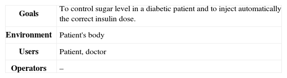
Step one: In the first Step, we specify all safety requirements. For safety requirements we need to investigate the system in detail which includes the goals of the system, environments, users, operators, and preliminary resources. These goals are shown in Table 1 for CIIP.
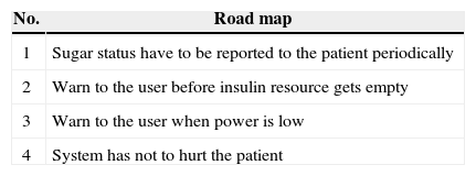
Some of the equipment needed in CIIP are sampling and injecting equipment, insulin resource, processor, LCD, and warning systems. A high level description of CIIP behavior is as follows: The system takes a sample of patient blood every 10 minutes, computes suitable insulin dose, and injects insulin to the patient's blood. High level safety approach for CIIP is depicted in Table 2.
For CIIP, the system requirements consist of realtime operating systems, some modeling tools, realtime programming languages and PCs. Hardware requirements consist of processors, memories, insulin reservoirs, sugar sampling equipment, insulin injection equipment, LCDs and power supplies. Functional requirements of CIIP are as follows:
- 1.
The system receives a sample of sugar blood every 10 minutes.
- 2.
The system processes sugar blood and computes the sugar level.
- 3.
The system computes insulin dose according to the last three sugar samples and injects insulin to the patient's blood.
Nonfunctional requirements are usually data requirements extracted from medical documents. These requirements are the following:
- 1.
If the sugar level is smaller than the minimum value, the insulin dose is 0.
- 2.
If the sugar level is between the minimum and the maximum value, then:
- •
If the third sugar sample is smaller or equal to the second sample, insulin dose is 0.
- •
If the third sugar sample is greater than the second sample and the second sample is greater than the first one, and the difference between the third sample and the second one is smaller or equal than the difference between the second sample and the first one, insulin dose is 0.
- •
If the third sugar sample is greater than the second sample and the second sample is greater than the first one, and the difference between the third sample and the second one is smaller or equal than the difference between the second sample and the first one and the difference between the third and the second sample is smaller than 4, the insulin dose is the minimum value.
- •
If the third sugar sample is greater than the second sample and the second sample is greater than the first one, and the difference between the third sample and the second one is smaller or equal than the difference between the second sample and the first one and the difference between the third and the second sample is greater than 4, the insulin dose is the quotient of the difference between the third and the second sample by 4.
- •
- 3.
If the sugar level is greater than the maximum value, then:
- •
If the third sugar sample is greater than the second sample and their difference is smaller than 4, the insulin dose is 0.
- •
If the third sugar sample is equal to the second sample, the insulin dose is 0.
- •
If the third sugar sample is smaller than the second sample and the difference between the third sample and the second one is smaller or equal than the difference between the second sample and the first one, the insulin dose is 0.
- •
If the third sugar sample is smaller than the second sample and the difference between the third sample and the second one is greater than the difference between the second sample and the first one, the insulin dose is the minimum value.
- •
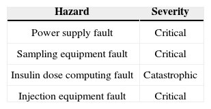
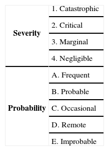
After specifying functional and nonfunctional requirements, we need to specify system hazards. Most of the hazard standards propose four hazard severity classes; catastrophic, critical, marginal, and negligible [12]. High level hazards for CIIP are shown in Table 3 according to this classification. The risk of each hazard can be determined using a combination of a digit and a letter which is shown in Table 4[13].
High level hazard classification for CIIP [12].
| Hazard | Severity |
|---|---|
| Power supply fault | Critical |
| Sampling equipment fault | Critical |
| Insulin dose computing fault | Catastrophic |
| Injection equipment fault | Critical |
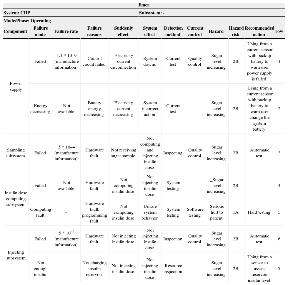
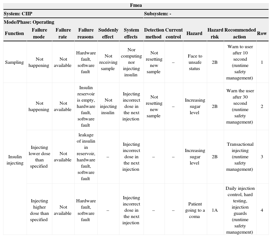
FMEA is a technique used in combination of hazard analysis in the proposed approach. There are three FMEA classes: Structural FMEA used for hardware analysis, functional FMEA used for system functions analysis and Combined FMEA [13]. Structural FMEA worksheet and functional FMEA worksheet for CIIP are shown in Table 5 and Table 6, respectively. These tables are updated in the next phases of this step.
Safety requirements may be defined in terms of constraints, chains of events, time constraints, fault tolerance equipment and warning interfaces. Safety requirements are classified as pure safety requirements, significant safety requirements, system safety requirements, and safety constraints [11]. This classification for CIIP is explained in detail in the following section. Each requirement must be mapped to at least one row of FMEA worksheets.
Pure safety requirements:
- •
System has not to have a risk in 1A rate
Safety significant requirements:
- •
If power is lower than the min level, a low power message has to be shown to the user and sampling operation must be suspended until power recharging takes place (rows 1, 2 from structural FMEA).
- •
Sampling equipment has to be tested automatically. Sampling operation must be stopped if this equipment does not work perfectly (row 3 from structural FMEA).
- •
Injecting equipment has to be tested automatically. Injecting operation must be stopped if this equipment does not work perfectly (row 6 from structural FMEA).
- •
If the amount of insulin in the reservoir is smaller than the min insulin dose or specified injection dose, a low insulin message has to be shown to the user and injecting operation must be stopped (row 7 from structural FMEA).
- •
The amount of cumulative dose at the end of every 24 hours can be at most 25 doses (row 4 from structural FMEA, medical rules)
Safety system requirements:
- •
An electricity-current evaluator system equipped with current sensor, backup battery, and LCD (rows 1, 2 from structural FMEA).
- •
Insulin-level determinant system for insulin reservoir (row 7 from structural FMEA)
- •
Warning equipment (rows 1, 2 from structural FMEA and rows 1, 2 from functional FMEA)
| Fmea | |||||||||||
|---|---|---|---|---|---|---|---|---|---|---|---|
| System: CIIP | Subsystem: - | ||||||||||
| Mode/Phase: Operating | |||||||||||
| Component | Failure mode | Failure rate | Failure reasons | Suddenly effect | System effect | Detection method | Current control | Hazard | Hazard risk | Recommended action | row |
| Power supply | Failed | 1.1 * 10–9 (manufacture information) | Control circuit failed | Electricity current disconnection | System downs | Current test | Quality control | Sugar level increasing | 2B | Using from a current sensor with backup battery to warn user power supply is failed | 1 |
| Energy decreasing | Not available | Battery energy decreasing | Electricity current decreasing | System incorrect action | Current test | – | Sugar level increasing | 2B | Using from a current sensor with backup battery to warn user change the system battery | 2 | |
| Sampling subsystem | Failed | 5 * 10–4 (manufacture information) | Hardware fault | Not receiving sugar sample | Not computing and injecting insulin dose | Inspecting | Quality control | Sugar level increasing | 2B | Automatic test | 3 |
| Insulin dose computing subsystem | Failed | Not available | Hardware fault | Not computing insulin dose | Not injecting insulin dose | System testing | – | _Sugar level increasing | 2B | – | 4 |
| Computing fault | – | Hardware fault, programming fault | Not computing insulin dose | Unsafe system behavior | System testing | Software testing | Serious hurt to patient | 1A | Hard testing | 5 | |
| Injecting subsystem | Failed | 5 * 10−4 (manufacture information) | Hardware fault | Not injecting insulin dose | Not injecting insulin dose | Inspection | Quality control | Sugar level increasing | 2B | Automatic test | 6 |
| Not enough insulin | – | Not charging insulin reservoir | Not injecting insulin dose | Not injecting insulin dose | Resource inspection | – | Sugar level increasing | 2B | Using from a sensor to assess reservoir insulin level | 7 | |
Safety constraints obtained from recommended reaction in FMEA worksheet with runtime management tag are as follows:
- •
A sampling operation must be finished at most 10 seconds after sampling starts otherwise, a sampling failure message must be shown to the user and the system has to be turned off (row 1 from functional FMEA).
- •
An insulin injection is an atomic operation (row 2 from functional FMEA).
- •
If the sugar level is low, the system must avoid injecting insulin to the patient's blood (row 4 from functional FMEA).
- •
Insulin dose for injection must not exceed the max dose (row 4 from functional FMEA).
- •
Injecting operation must be finished at most 30 seconds after sampling starts otherwise, an injection failure message must be shown to the user and system has to be turned off (row 2 from functional FMEA).
Step two: After identifying safety requirements, we model the system such that it satisfies all safety requirements [14]. We proposed two system units: operation unit that interacts with the environment (the patient) directly, and control unit that controls and supports the operation unit. Figure 1 shows this interactive model.
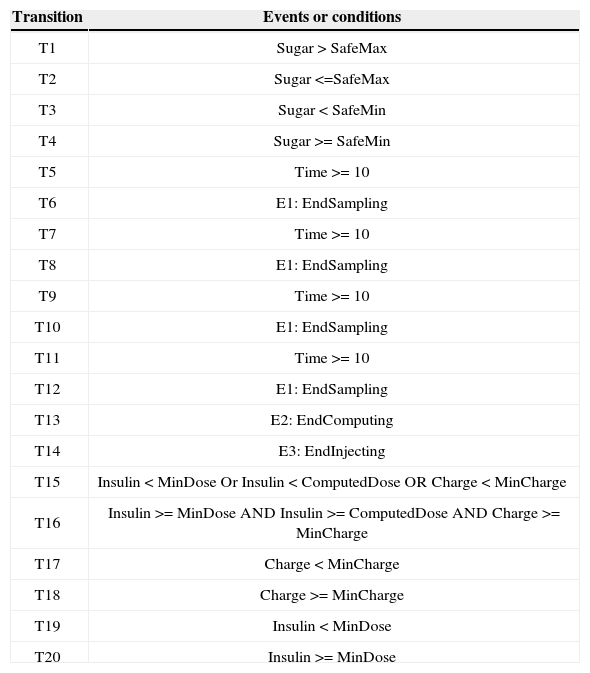
We use timed transition Petri-net as the formal method because of its tractable behavior and its support of time. In addition, we use Z [17] to specify textual and mathematical specifications as a complement for Petri-net. A Petri-net model includes places, tokens, arcs and transitions. Each transition associates with a condition which, when holds, causes tokens on the transition to move to the next place. A Petri-net model for logical behavior of CIIP is shown in Figure 2.
All transitions in Figure 2 are explained in Table 7 similar to the proposed model in [8].
| Fmea | |||||||||||
|---|---|---|---|---|---|---|---|---|---|---|---|
| System: CIIP | Subsystem: - | ||||||||||
| Mode/Phase: Operating | |||||||||||
| Function | Failure mode | Failure rate | Failure reasons | Suddenly effect | System effects | Detection method | Current control | Hazard | Hazard risk | Recommended action | Row |
| Sampling | Not happening | Not available | Hardware fault, software fault | Not receiving sample | Nor computing nor injecting insulin | Not resetting new sample | – | Face to unsafe status | 2B | Warn to user after 10 second (runtime safety management) | 1 |
| Insulin injecting | Not happening | Not available | Insulin reservoir is empty, hardware fault, software fault | Not injecting insulin | Injecting incorrect dose in the next injection | Not resetting new sample | – | Increasing sugar level | 2B | Warn the user after 30 second (runtime safety management) | 2 |
| Injecting lower dose than specified | Not available | leakage of insulin in reservoir, hardware fault, software fault | – | Injecting incorrect dose in the next injection | – | – | Increasing sugar level | 2B | Transactional injecting (runtime safety management) | 3 | |
| Injecting higher dose than specified | Not available | Hardware fault, software fault | – | Injecting incorrect dose in the next injection | – | – | Patient going to a coma | 1A | Daily injection control, hard testing, injection guards (runtime safety management) | 4 | |

Transitions on the CIIP Petri-net model.
| Transition | Events or conditions |
|---|---|
| T1 | Sugar > SafeMax |
| T2 | Sugar <=SafeMax |
| T3 | Sugar < SafeMin |
| T4 | Sugar >= SafeMin |
| T5 | Time >= 10 |
| T6 | E1: EndSampling |
| T7 | Time >= 10 |
| T8 | E1: EndSampling |
| T9 | Time >= 10 |
| T10 | E1: EndSampling |
| T11 | Time >= 10 |
| T12 | E1: EndSampling |
| T13 | E2: EndComputing |
| T14 | E3: EndInjecting |
| T15 | Insulin < MinDose Or Insulin < ComputedDose OR Charge < MinCharge |
| T16 | Insulin >= MinDose AND Insulin >= ComputedDose AND Charge >= MinCharge |
| T17 | Charge < MinCharge |
| T18 | Charge >= MinCharge |
| T19 | Insulin < MinDose |
| T20 | Insulin >= MinDose |
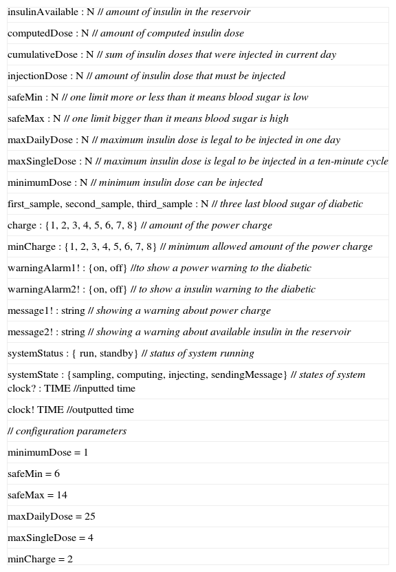
As shown in Figure 2, the operation unit has four main states; Idle, Sampling, Computing, and Injecting. A token moves from Idle state to Injecting state when transitions are fired according to the conditions in Table 7. Diagrams are not convenient tools to specify the requirements; instead, we use Z as a textual formal method to do so. Schemas 1 to 6 specify CIIP requirements similar to [8]. Each schema has a declaration part and a predicate part. For example schema 1 specifies states and their initial values. In this schema, insulinAvailable shows the available insulin in the reservoir. Also this schema has a predicate minimumDose that specifies the amount of minimum insulin for injection.
the sugar level is high and low, respectively. Last three schemas specify computing state in the Petri-net model. Because the lack of space, we Schema 2 specifies the behavior of the system when running. Schema 3, specifies data requirements when the sugar level is normal. Schemas 4 and 5 specify data requirements when the sugar level is high and low, respectively. Last three schemas specify computing state in the Petri-net model. Because the lack of space, we ignore schemas for other states including sampling and injecting.
| insulinAvailable : N // amount of insulin in the reservoir |
| computedDose : N // amount of computed insulin dose |
| cumulativeDose : N // sum of insulin doses that were injected in current day |
| injectionDose : N // amount of insulin dose that must be injected |
| safeMin : N // one limit more or less than it means blood sugar is low |
| safeMax : N // one limit bigger than it means blood sugar is high |
| maxDailyDose : N // maximum insulin dose is legal to be injected in one day |
| maxSingleDose : N // maximum insulin dose is legal to be injected in a ten-minute cycle |
| minimumDose : N // minimum insulin dose can be injected |
| first_sample, second_sample, third_sample : N // three last blood sugar of diabetic |
| charge : {1, 2, 3, 4, 5, 6, 7, 8} // amount of the power charge |
| minCharge : {1, 2, 3, 4, 5, 6, 7, 8} // minimum allowed amount of the power charge |
| warningAlarm1! : {on, off} //to show a power warning to the diabetic |
| warningAlarm2! : {on, off} // to show a insulin warning to the diabetic |
| message1! : string // showing a warning about power charge |
| message2! : string // showing a warning about available insulin in the reservoir |
| systemStatus : { run, standby} // status of system running |
| systemState : {sampling, computing, injecting, sendingMessage} // states of system clock? : TIME //inputted time |
| clock! TIME //outputted time |
| // configuration parameters |
| minimumDose = 1 |
| safeMin = 6 |
| safeMax = 14 |
| maxDailyDose = 25 |
| maxSingleDose = 4 |
| minCharge = 2 |
ΔPUBLIC_STATES
clock? = 001000 ➔ (clock! = 000000) ∧ (injectionDose' = 0) ∧ (computedDose' = 0) A (first_sample' =
second_sample) ∧ (second _sample' = third_sample) ∧ (third _sample' = 0)
systemStatus = run ∨ standby
// dose of insulin is computed depending on the blood sugar level
SUGAR_NORMAL ∨ SUGAR_HIGH ∨ SUGAR_LOW
// safety rules
SAFETY
cumulativeDose' = cumulativeDose + injectionDose
systemStatus = run
systemState = Computing
(third_sample >= safeMin) ∧ (third_sample <= safeMax)
// sugar level stable or falling
(third_sample <= second_sample)➔(computedDose = 0)
// sugar level increases but rate of increase falls
(third_sample > second_sample) ∧(third_sample - second_sample) < (second_sample - first_sample)
➔(computedDose = 0)
// sugar level increases and rate of increase increases compute dose
// a minimum dose must be delivered if rounded to zero
(third_sample > second_sample) ∧(third_sample - second_sample) >= (second_sample - first_sample)
∧(round((third_sample - second_sample)/4) = 0) ➔(computedDose = minimumDose)
(third_sample > second_sample) A(third_sample - second_sample) >= (second_sample - first_sample)
∧(round((third_sample - second_sample)/4) > 0) ➔(computedDose = round((third_sample -
second_sample)/4)
S ystemStatus = run
systemState = Computing
third_sample > safeMax
// sugar level increasing. Round down if below 1 unit
(third_sample > second_sample) ∧(round((third_sample- second_sample)/4) = 0) ➔(computedDose =
minimumDose)
(third_sample > second_sample) ∧(round((third_sample-second_sample)/4) > 0) ∧(computedDose =
round((third_sample - second_sample)/4))
// sugarlevel stable
(third_sample = second_sample) ➔(computedDose = minimumDose)
// sugar level falling and rate of increase decreasing
(third_sample < second_sample) ∧(third_sample - second_sample) <= (second_sample - first_sample)
➔(computedDose = 0)
// sugar level falling and rate of increase increasing
(third_sample < second_sample) ∧(third_sample - second_sample) > (second_sample - first_sample)
systemStatus = run
systemState = Computing
third_sample < safeMin
computedDose = 0
warningAlarm! = on
message! = “Your sugar is very low. Please call your doctor.”
charge < minCharge ➔ (warningAlarm1! = on) ∧ (messag e1!= “Low charge.”) A (systemStatus = standby)
charge >= minCharge ➔ (warningAlarm1! = off) ∧ (message1! = “”) ➔ (systemStatus = run)
(insulinAvailable < minDose ) ∨ (insulinAvailable < injectionDose) ➔ (warningAlarm2! = on) A (message2! =
“Low insulin.”) ∧ (systemStatus = standby)
(insulinAvailable > minDose ) ∨ (insulinAvailable > injectionDose) ➔ (warningAlarm2! = off) A (message2! =
’”) A (systemStatus = run)
cumulativeDose <= 25 ➔ injectionDose = computedDose
cumulativeDose > 25 ➔ injectionDose = 0
Step three: Even using the most sophisticated techniques for controlling the safety in both, requirements layer and design layer, it is always possible an unexpected error causes a system failure at runtime. Therefore, to avoid any system failure, we need to monitor the behavior of the system at runtime to identify and manage unexpected faults. In the proposed approach, all the main states of the system are monitored continuously in a structure which includes four units: Log management, change management, prevention management and disaster management which are based on information technology infrastructure library (ITIL) 20.
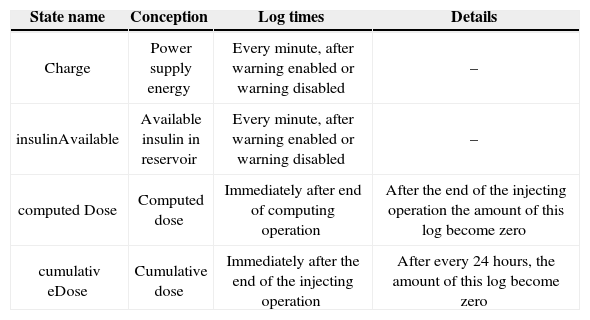
Log management logs the main sates of the system when they change. As a result, all required states must be identified first. The main candidates for logging are those which changes may result in a critical behavior. Main critical behavior of CIIP is insulin injection; because incorrect insulin injection may hurt the patient seriously. Critical states that are in our concern shown in Table 8. These states must be logged.
Critical states of CIIP.
| State name | Conception | Log times | Details |
|---|---|---|---|
| Charge | Power supply energy | Every minute, after warning enabled or warning disabled | – |
| insulinAvailable | Available insulin in reservoir | Every minute, after warning enabled or warning disabled | – |
| computed Dose | Computed dose | Immediately after end of computing operation | After the end of the injecting operation the amount of this log become zero |
| cumulativ eDose | Cumulative dose | Immediately after the end of the injecting operation | After every 24 hours, the amount of this log become zero |
Because critical behavior of the system may change over time, we need a change management unit to confirm that the change is safe. This unit is constructed from the high level constraints of the system and the environment conditions. Before giving permission to any critical behavior, required states are obtained from log management to ensure that all of them are safe. Change management unit plays a role in design, similar to the role of exception management in programming. Table 9 shows change permissions for the beginning of injecting critical behavior of CIIP. We can extend this table for other critical behaviors of CIIP which are in the second level of importance.
Change permissions for critical behavior of CIIP
| Critical behavior | Conditions | Permission |
|---|---|---|
| Beginning of the injecting operation | Charge > minCharge AND insulinavailable > minDose AND ComputedDose > 0 AND cumulativeDose <=25 | True |
| ∼( Charge > minCharge AND insulinavailable > minDose AND ComputedDose > 0 AND cumulativeDose <=25) | False |
To detect existing faults of the system before entering to critical states at runtime, a prevention management is required. Because CIIP is a real-time system, it is better to design prevention management such that it runs in parallel with the system. Schema 7 specifies prevention management in Z language for CIIP. When any condition in this schema fails, disaster management is called.
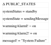
Disaster management unit is a complement for the prevention unit. It tries to escape from faulty situations of the system, those which cannot be predicted in normal behavior and may lead to a catastrophic status. Disaster management can be as simple as showing a warning to the user, or as complex as replacing a redundant hardware, or as urgent as turning off the whole system. Disaster management for CIIP can be designed to turn off the system, show a message about system failure, and send a message to the patient's doctor through communication lines. Schema 8 specifies disaster management for CIIP in Z language.
Emergency4ConclusionsAchieving a high degree of safety in safety-critical software requires that designers think about it carefully in each step of the software production. However, current approaches usually focus on safety in only one phase of the software production. In this paper, we proposed a multi-phase approach to achieve safety in safety-critical software. To describe the behavior of the system formally, we used timed transition Petri-net and the Z language. To show the proposed approach practically, we used CIIP as a sample model.