


The main purpose of this study is to analyze the thermomechanical behavior of the dry contact between the brake disc and pads during the braking phase. The simulation strategy is based on computer code ANSYS11. The modeling of transient temperature in the disc is actually used to identify the factor of geometric design of the disc to install the ventilation system in vehicles. The thermo-structural analysis is then used with coupling to determine the deformation established and the Von Mises stresses in the disc, the contact pressure distribution in pads. The results are satisfactory when compared to those found in previous studies.
Deceleration of the vehicle, ms−2
Disc surface swept by a brake pad, m2
Thermal capacity matrix, JK−1
Specific heat, Jkg−1K−1
Young modulus, GPa
Gravitational Acceleration, 9.81 ms−2
Convective heat transfer coefficient, Wm−2K−1
Thermal conductivity, Wm−1K−1
Thermal conductivity matrix, WK−1
Vector operator
Mass of the vehicle, kg
Unit normal
Heat flux entering the disc, W
Heat quantity generated during the friction, J
Heat flux specified on a surface, W
Surface temperature, m2
Surface in heat flux, m2
Surface in convection, m2
Time, s
Temperature, °C
Temperature specified on a surface, °C
Fluid temperature, °C
Temperature imposed, °C
Initial speed of the vehicle, ms−1
Vector speed of mass transport
Braking effectiveness
Thermal expansion coefficient, °C−1
Factor load distribution on the disc surface
Poisson coefficient
Mass density, kgm−3
Kinematic viscosity, m2s−1
Rate distribution of the braking forces between the front and rear axle
Nowadays, composite materials are used in large volume in various engineering structures including spacecrafts, airplanes, automobiles, boats, sport equipment, bridges and buildings. The widespread use of composite materials in industry is due to their excellent characteristics such as, specific strength and specific hardness or strength-weight ratio and hardness-weight ratio [1]. In practice, most brake discs are made from cast iron. Which once in use, sometimes are subjected to high thermal stresses, this can lead to permanent plastic deformation and occasionally rotor cracking. The braking system represents one of the most fundamental safetycritical components in modern passenger cars. Therefore, the braking system of a vehicle is undeniably important, especially when slowing down or stopping the rotation of a wheel by pressing the brake pads against the rotating wheel discs. Braking performance of a vehicle can significantly be affected by the temperature rise in the brake components. The frictional heat generated at the interface of the disc and the pads can cause a high temperature.
Particularly, the temperature may exceed the critical value for a given material, which could bring undesirable effects, such as brake fade, local scoring, thermo elastic instability, premature wear, brake fluid vaporization, bearing failure, thermal cracks, and thermally excited vibration [2].
Gao and Lin [3], stated that there is considerable evidence that shows that contact temperature is an integral factor reflecting the specific power friction influence of the combined effect of load, speed, friction coefficient, and the thermo physical and durability properties of the materials of a frictional couple. Lee and Yeo [4], reported that uneven distribution of temperature at the surfaces of the disc and friction pads brings about thermal distortion, which is known as coning and found to be the main cause of judder and disc thickness variation (DTV). Ouyang et al. [5] in their recent work found that temperature could also affect the vibration level in a disc brake assembly. In a recent work, Ouyang et al. [5] and Hassan et al. [6] employed finite element approach to investigate thermal effects on disc brake squeal using dynamic transient and complex eigenvalue analysis, respectively. Braking system is the single most important safety feature of every vehicle on the road. The capability of the braking system to bring the vehicle to a safe-controlled stop is absolutely essential in preventing accidental vehicle damage and personal injury. Safety during emergency braking is very much related with the braking capability of each vehicle. Once this capability is known, it is possible to set appropriate minimum intervehicle distances that will preserve safety during emergency braking. Braking capability depends mostly on the tire-road contact forces. These are difficult to know precisely because they change with the type of tire, road and weather conditions [7]. The braking system is composed of many parts, including friction pads on each wheel, a master cylinder, wheel cylinders, and a hydraulic control system [8].
Disc brake consists of cast-iron disc which rotates with the wheel, caliper fixed to the steering knuckle and friction material (brake pads). When the braking process occurs, the hydraulic pressure forces the piston therefore, pads and disc brake come in sliding contact. Set up force resists the movement and the vehicle slows down or eventually stops.
Friction between disc and pads always opposes motion and the heat is generated due to conversion of the kinetic energy [9]. The three-dimensional simulation of thermo-mechanical interactions on the automotive brake, showing the transient thermoelastic instability phenomenon, is presented for the first time in this academic community [10].
In this work, we will make a model of the thermomechanical behavior of the dry contact between the discs of brake pads at the time of braking phase; the strategy of calculation is based on the software Ansys [11]. This last one is elaborate mainly for the resolution of the complex physical problems. The numerical simulation of the coupled transient thermal field and stress field is carried out by sequential thermal-structural coupled method based on Ansys.
2Numerical modeling of the thermal problem2.1Equation of the problemThe first law of thermodynamics indicating the thermal conservation of energy gives:

In our case there is not an internal source (p=0), thus, Equation 1 is written:

With:


Fourier's law (2) can be written in the following matrix form:
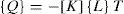
With:
kx, ky and kz Represent the thermal conductivity along axes x, y, z respectively. In our case the material is isotropic thus kxx = kyy = kzz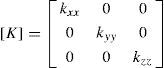
▪{L} Vector operator.
▪{v} Vector speed of mass transport.
▪[K] Conductivity matrix.
By combining Equations 2 and 5, we obtain:

By developing Equation 7, we obtain:
2.2Initial conditions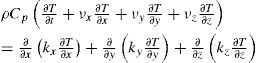
According to experimental tests evoked in previous works. In our study, we consider that the initial temperature is equal:
2.3Boundary conditions
In general, in a thermal study, we find three types of boundary conditions:
▪Temperature specified on a surface

▪Heat flux entering the disc
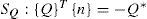
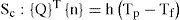
▪Convection specified on a surface
In a braking system, the mechanical energy is transformed into a caloric energy. This energy is characterized by the total heating of the disc and pads during the braking phase. The energy dissipated in the form of heat can generate increases in temperature ranging from 300°C to 800°C. Generally, the thermal conductivity of the material of the brake force pads is lower than that of the disc (kp < kd). We consider that the heat quantity produced will be completely absorbed by the brake disc. The heat flux evacuated of this surface is equal to the power friction. The initial heat flux q0 entering the disc is calculated by the following formula [12]:
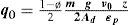
Figure 1 shows the ventilated disc-pads and the applied forces.

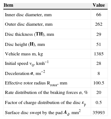
The loading corresponds to the heat flux on the disc surface. The dimensions and the parameters used in the thermal calculation are recapitulated in Table 1.
Geometric dimensions and application parameters of automotive braking.
| Item | Value |
|---|---|
| Inner disc diameter, mm | 66 |
| Outer disc diameter, mm | 262 |
| Disc thickness (TH), mm | 29 |
| Disc height (H), mm | 51 |
| Vehicle mass m, kg | 1385 |
| Initial speed v0, kmh−1 | 28 |
| Deceleration a, ms−2 | 8 |
| Effective rotor radius Rrotor, mm | 100.5 |
| Rate distribution of the braking forces ø, % | 20 |
| Factor of charge distribution of the disc εp | 0.5 |
| Surface disc swept by the pad Ad, mm2 | 35993 |
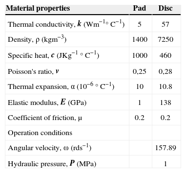
The disc material is gray cast iron (FG) with high carbon content [13], with good thermophysical characteristics. The brake pad has an isotropic elastic behavior which thermomechanical characteristics adopted in this simulation in the transient analysis of the two parts are recapitulated in Table 2.
Thermoelastic properties used in simulation.
| Material properties | Pad | Disc |
|---|---|---|
| Thermal conductivity, k (Wm−1°C−1) | 5 | 57 |
| Density, ρ (kgm−3) | 1400 | 7250 |
| Specific heat, c (JKg−1 °C−1) | 1000 | 460 |
| Poisson's ratio, v | 0,25 | 0,28 |
| Thermal expansion, α (10−6 °C−1) | 10 | 10.8 |
| Elastic modulus, E (GPa) | 1 | 138 |
| Coefficient of friction, μ | 0.2 | 0.2 |
| Operation conditions | ||
| Angular velocity, ω (rds−1) | 157.89 | |
| Hydraulic pressure, P (MPa) | 1 |
The first stage is to create the CFD model which contains the fields to be studied in Ansys Workbench. In our case, we took only one quarter of the disc. Then, we defined the field of the air surrounding this disc. ANSYS ICEM CFD will prepare various surfaces for the two fields in order to facilitate the mesh on which we will export the results towards CFX using the command “Output to cfx” [14]. After obtaining the model on CFX Pre and specifying the boundary conditions, we must define these physical values come into play on CFX to start calculation.
The disc is related to four adiabatic surfaces and two surfaces of symmetry in the fluid domain which ambient temperature on the air is taken to be equa to 20 °C [15]. In order not to weigh down calculations, an irregular mesh is used in which the meshes are broader where the gradients are weaker (non-uniform mesh).
Figure 2. Shows the elaborate CFD model which will be used in ANSYS CFX Pre.

In this step, we declare all of the physical characteristics of the fluid and the solid. We introduce into the library the physical properties of used materials. In this study we selected cast iron material (FG 15) with its thermal conductivity (57 W/m°C). Because the aim of this study is to determine the temperature field in a disc brake during the braking phase of a vehicle of average class, we take the following temporal conditions:
▪Braking time= 3.5 [ s ]
▪Increment time = 0.01 [ s]
▪Initial time = 0 [ s]
Before starting the calculation and the analysis with ANSYS CFX PRE, it is ensured that the model does not contain any error.
After the verification of the model and boundary conditions, we run the calculation by opening the menu “File” and clicking on “Write solver file”. The values of the coefficient of exchange will be taken as the average values calculated by the minimal and maximum values obtained using ANSYS CFX POST as indicated in Figure 3.
5Meshing of the disc.")
The elements used for the meshing of the full and ventilated disc are tetrahedral three-dimensional elements with 10 nodes (isoparametric) (Figure 4). In this simulation, the meshing was refined in the contact zone (disc-pad).This is important because in this zone the temperature varies significantly. Indeed, in this strongly deformed zone, the thermomechanical gradients are very high. That is why the correction taking into account of the contact conditions involves the use of a refined mesh.
6Loading and boundary conditions full disc (172103 nodes -114421 elements) (b) ventilated disc (154679 nodes- 94117 elements).")
The thermal loading is characterized by the heat flux entering the disc through the real contact area (two sides of the disc). The initial and boundary conditions are introduced into the module ANSYS Workbench. The thermal calculation will be carried out by choosing the transient state and by introducing the physical properties of the materials. The selected data for the numerical application are summarized as follows:
▪Total time of simulation = 45 [s]
▪Increment of initial time = 0.25 [s]
▪Increment of minimal initial time = 0.125 [s]
▪Increment of maximal initial time = 0.5 [s]
▪Initial temperature of the disc = 60 [°C]
▪Material: Gray cast iron (FG 15).
The modeling of temperature in the disc brake will be carried out by taking account of the variation of certain number of parameters such as the type of braking, the cooling mode of the disc and the choice of disc material. The brake discs are made of cast iron with high carbon content; the contact surface of the disc receives an entering heat flux calculated by relation (13).
7.1Influence of construction of the discFigure 5, shows the variation of the temperature versus time during the total time simulation of braking for a full disc and a ventilated disc. The highest temperatures are reached at the contact surface dis-pads. The high rise in temperature is due to the short duration of the braking phase and to the speed of the physical phenomenon. Of the two types of discs, we can notice that starting from the first step of time we have a fast rise in the temperature of the disc followed by a fall in temperature after a certain time of braking.
 and ventilated disc (b) of cast iron (FG 15).")
We quickly notice that for a ventilated disc made out of cast iron FG15, the temperature increases until Tmax = 345 °C at the moment t=1.85 s, then it decreases rapidly in the course of time. The variation in temperature between a full and ventilated disc of the same material is about 60 °C at the moment t=1.88 s. We can conclude that the geometric design of the disc is an essential factor in the improvement of the cooling process of the discs.
8Coupled thermomechanical analysis8.1FE model and boundary conditionsThe purpose of the analysis is to predict the temperatures and corresponding thermal stresses in the brake disc when the vehicle is subjected to sudden high-speed stops as may occur under autobahn driving conditions [16]. A commercial front disc brake system consists of a rotor that rotates about the axis of a wheel, a caliper-piston assembly where the piston slides inside the caliper, which is mounted to the vehicle suspension system, and a pair of brake pads. When hydraulic pressure is applied, the piston is pushed forward to press the inner pad against the disc, and simultaneously the outer pad is pressed by the caliper against the disc [17]. In a real car disc brake system, the brake pad surface is not smooth at all. Abu Bakar and Ouyang [18] adjusted the surface profiles using measured data of the surface height and produced a more realistic model for brake pads. Figure 6 shows the FE model and boundary conditions embedded configurations of the model composed of a disc and two pads. The initial air temperature of the disc and the pads is 20°C, and the surface convection condition is applied to all surfaces of the disc, and the convection coefficient (h) of 5 W/m2°C is applied to the surfaces of the two pads.

The FE mesh is generated using threedimensional tetrahedral element with 10 nodes (solid 187) for the disc and pads. Overall 185,901 nodes and 113367 elements are used (Figure 7). In this work, a transient thermal analysis will be carried out to investigate the temperature variation across the disc using Ansys software. Further structural analysis will also be carried out by coupling thermal analysis.
8.2Thermal deformation
Figure 8, gives the distribution of the total distortion in the whole (disc-pads) for various moments of simulation. For this figure, the scale of values of the deformation varies from 0 to 284 µm. The t value of the maximum displacement recorded during this simulation is at the moment, t=3.5 s which corresponds to the time of braking. We observe a strong distribution which increases with time on the friction tracks, and the external crown and the cooling fins of the disc. Indeed, during a braking moment, the maximum temperature depends almost entirely on the heat storage capacity of the disc (on particular tracks of friction); this deformation will generate a disc asymmetry following the rise in temperature which will cause a deformation in the shape of an umbrella.
8.3Von Mises stress distribution
Figure 9, presents the distribution of the constraint equivalent of Von Mises for various moments of simulation, the scale of values varying from 0 to 495 MPa. The maximum value recorded during this simulation of the thermomechanical coupling is very significant compared to that obtained with the assistance in the mechanical analysis under the same conditions. We observe a strong constraint on the level of the bowl of the disc. Indeed, the disc is fixed to the hub of the wheel by screws, preventing its movement. In the presence of the rotation of the disc and the requests of torsional stress and sheers generated at the level of the bowl which are able to create the stress concentrations. The repetition of these effects will lead to risks of rupture on the level of the bowl of the disc.
8.4Contact pressure
Due to thermal deformation, contact area and pressure distribution also change. Thermal and mechanical deformations affect each other strongly and simultaneously. Because pressure distribution is another important aspect concerned with this research, it will be studied in the context of uneven temperature distributions. Contact analysis of the interfacial pressure in a disc brake without considering thermal effects was carried out in the past i.e., in Tirovic and Day [19]. Brake squeal analysis in recent years always includes a static contact analysis as the first part of the complex eigenvalue analysis [20,21].
Figure 10, shows the contact pressure distribution in the friction interface of the inner pad taken at various times of simulation. For this distribution the scale varies from 0 to 3.3477 MPa and reached a value of pressure at the moment t=3.5 s, which corresponds to the null rotational speed. It is also noticed that the maximum contact pressure is located on the edges of the pad decreasing from the leading edge toward the trailing edge from friction. This pressure distribution is almost symmetrical compared with the groove, and it has the same tendency as that of the distribution of the temperature because the highest area of the pressure is located in the same sectors. Indeed, at the time of the thermomechanical coupling of 3d, the pressure produces the symmetric field of the temperature. This last one affects thermal dilation and leads to a variation of the contact pressure distribution.
9Conclusion
In this publication, we presented the analysis of the thermomechanical behavior of the dry contact between the brake disc and pads during the braking process; the modeling was based on the ANSYS 11.0. We demonstrated that the ventilation system plays an important role in cooling the discs and provides a good high temperature resistance.The analysis results showed that, temperature field and stress field in the process of braking phase were fully coupled. The temperature, Von Mises stress, and the total deformations of the disc and contact pressures of the pads increased because the thermal stresses are additional to mechanical stress which caused the crack propagation and fracture of the bowl and wears off the disc and pads. Regarding the calculation results, we can say that they were satisfactory just as they can be commonly found in previous investigations. Furthermore, it would be interesting to solve the problem in thermomechanical disc brakes with an experimental study to validate the numerical results, for example on test benches, in order to show a good agreement between the model and reality