


The surface deformation detection of an object has been a very popular research project in recent years; in human vision, we can easily detect the location of the target and that scale of the surface rotation, and change of the viewpoint makes the surface deformation, but in a vision of the computer is a challenge. In those backgrounds of questions, we can propose a framework that is the surface deformation, which is based on the detection method of BRIEF to calculate object surface deformation. But BRIEF calculation has some problem that can’t rotate and change character; we also propose a useful calculation method to solve the problem, and the method proved by experiment can overcome the problem, by the way, it's very useful. The average operation time every picture in continuous image is 50∼80ms in 2.5GHz computer, let us look back for some related estimation technology of surface deformation, and there are still a few successful project that is surface deformation detection in the document.
Object surface deformation detection has been a rather popular research topic in recent years and subsequent applications have also been extensive. Augmented reality (AR) is an interesting man-machine interaction technology in which a filming camera is used in combination with an effective algorithm for image calculation to enable interaction between people and virtual images, making hardware equipment become more than just computation tools but also allowing lively and fun man-machine interaction. The incessant quest of humans for novelty, speed, and innovation has provided the drive behind advancements in information technology and prices have also become more affordable, unlike the high costs that limited the availability of hardware equipment in the past. Kinect, that Microsoft released for Xbox 360 in 2010, for instance, was a breakthrough both in hardware performance and price wise. Previously, hardware equipment of such specifications could easily cost hundreds of thousands of New Taiwan (NT) dollars, but today people are able to acquire such equipment by spending a few thousand dollars.
Due to the affordability of hardware prices and upgrades in computation speeds, the growth of AR application and services has been amazing. The market value increase from 2010 to 2013 has been rather considerable. This means that object surface deformation estimation will remain a worthwhile topic and objective of studies for quite some time.
Feature descriptors, sometimes called descriptors, have always been a popular research topic and a tough challenge. They are commonly used in algorithms for target detection and further applications such as automatic control, product inspection, face identification, and object tracking, etc. Such subsequent applications have resulted in problems that need solving, including detection of change of angle of view, scale and rotation of objects and multi-targets. Therefore, an effective algorithm is required to solve these problems. A detector is used to locate in an image the keypoints which can be edges or corners. The keypoints are then filtered to keep only the ones that meet the established conditions. The purpose is to facilitate detection and reduce the quantity of keypoints to be processed. The descriptors are applied to describe the features, such as the size and shape of an eye, to make the keypoints more distinguishable. In the end, matching between the template and the target is conducted and match results are generated. (Baker & Matthews, 2004) proposed a theory called image alignment to depict other algorithms and framework extension.
Scale-Invariant Feature Transform (SIFT) is a feature description method proposed by Lowe (2004). It is a pioneer in the feature description. When the SIFT algorithm is applied, the difference of Gaussians (DoG) is used first to figure out the gradient changes because distinct features like edges and corners are needed to calculate gradient directions in order to establish a pyramidal image to indicate the different scales, in other words different scaling ratios. In subsequence, feature description is conducted. The feature description in this paper is conducted from block to block to calculate the different gradient directions around a feature to identify the primary and secondary gradient directions, equip them with rotational invariance, and establish the descriptors (Yasmin et al., 2014; Yasmin et al., 2013).
H. Bay put forth Speeded Up Robust Features (SURF) (Bay et al., 2006), and proposed to apply the Hessian matrix to locate changeable keypoints and consolidate integral images to achieve scale invariance, same as the steps to establish the pyramidal image. The method greatly improved the bottleneck in SIFT computation speed because, after obtaining the overall integer value, it only requires the Hessian matrix of different sizes to indicate the image ratio changes resulted from different scales. Then, the keypoints around each keypoint are calculated and the direction with the most keypoints is regarded the direction of the said keypoint to achieve rotational invariance. Finally, the features around the keypoint are divided into feature descriptors carrying a symbol and not carrying a symbol.
M. Calonder came up with the Binary Robust Independent Elementary Features (BRIEF) (Calonder et al., 2010) algorithm. Since detectors used in algorithms developed in the past, such as SURF, could be used in search of initial keypoints and scales, Edward Rosten proposed in 2010 the FAST corner detector, while Elmar Mair also put forward the AGAST corner detector. Both algorithms were not only able to search initial keypoints quickly, but also reliable and capable of effectively reducing the cost of initial computation; they were therefore suitable to provide a good foundation for establishment of subsequent descriptors, while different image scale changes could also be identified by using integral images. They proposed the use of binary descriptors to break through the bottleneck encountered in studies on subsequent descriptor computation so that the cost of matching and descriptor computation could be reduced.
ORB (Rublee et al., 2006) is an algorithm proposed by Microsoft researcher E. Rublee in 2010. The paper was primarily to suggest ways to improve the defect of lack of rotational invariance of BRIEF, its initial keypoint filtering mechanism, and calculation of different keypoint directions. The keypoint search and scale changes could still be conducted in reference to detection methods adopted in algorithms developed in the past. In the beginning, the FAST method was applied to locate the keypoints in an image. The keypoints located were filtered to select the most reliable keypoints. Then, future directions are calculated in accordance with the intensity centroid of each of the selected keypoint to establish binary descriptors.
S. Leutenegger presented Binary Robust Invariant Scalable Keypoints (BRISK) (Leutenegger et al., 2011) in 2012. The main contribution of the paper was the approach of incorporation of AGAST detectors to locate keypoints with scale invariance and improve descriptors effectiveness. In the paper, it was described how AGAST detectors were able to locate keypoints effectively and reliably and the outcome and speed were at least as outstanding as those of FAST detectors. Also mentioned in the paper was a way to find reliable keypoints under different scales and an approach different from the methods adopted in past literature to establish DAISY descriptors to make the descriptors more robust.
In 2012, A. Alahi proposed FAST Retina Keypoint (FREAK) (Alahi et al., 2012) to establish descriptors based on the concept behind the human retina and claimed that the approach could lead to better results than BRISK, SURF and SIFT. Before performing the two descriptor matching, stages, the first section was first examined to see if it met the threshold and, if so, the matching for the second section was then conducted; thus, the cost of computation could be reduced.
Other papers released, including those by Ke and Sukthankar (2004), Dalal and Triggs (2005), and Mikolajczyk and Schmid (2005), were all related to feature descriptor algorithms. K. Mikolajczyk also published another paper in 2008 to discuss the comments about descriptors (Rosten, Porter & Drummond, 2010).
The framework of the algorithm put forward in this paper. First, the template and the target image are imported for detection and matching to obtain match results. Then, mismatches are rejected. The keypoint initially acquired is incorporated in the tracking algorithm to be the initial point and complementation is performed through detection and tracking. In the end, a deformation function is obtained according to the matching relationship between the template and the target. The objective of this algorithm is to find out how to conduct real-time non-rigid surface deformation detection by using feature descriptors.
2The proposed methodThe objective of this study is to identify with effectiveness the relationship between the matches of the template and target keypoints and then, according to the relationship, to establish a warp function that represents the coordinate conversion relationship between corresponding template target keypoints.
2.1FAST detectorThe purpose of detection is to locate the keypoints such as corners or edges in the image, and they would be described into the descriptors. How to effectually locate the keypoints, filtering and descriptors generation is main issue in this chapter (Yasmin et al., 2014; Yasmin et al., 2013).
The description of keypoint detection will be divided in two parts FAST (Features from Accelerated Segment Test) corner detection and FAST corner filtering.
In 2006, E. Rosten proposed the FAST (Rosten & Drummond, 2006; Tuytelaars & Mikolajczyk, 2008), a quick corner detection algorithm based on the idea of scanning one by one all the pixels in an image, and using each pixel as the center to detect whether the grayscale difference of the pixel on a radius point meets the grayscale difference threshold as well as calculate the number of pixels that meet the said threshold. If the cumulative number of pixels meets the quantity threshold, the pixel is selected as the FAST corner and the grayscale difference aggregate, corner response, is recorded. When this algorithm is applied, only simple addition and subtraction are required; therefore, performance optimization can be conducted by using SSE (Streaming SIMD Extensions) instruction sets.
FAST is a good algorithm for detection of corners in an image. Only simple addition and subtraction are needed, but the grayscale threshold setting is also required. Grayscale difference threshold parameter setting has always been a baffling issue because different questions call for different grayscale difference thresholds to meet the conditions in order to obtain decent results. For this reason (Rublee et al., 2006), the author proposes to apply low grayscale difference thresholds to detect the FAST corners in an image and then filter the corners detected and retain the ones meeting the requirements. FAST includes two steps for filtering the keypoints, N and M indicate the number of chosen keypoints in steps 1 and 2, respectively. The choice of the N and M parameters is conducted in accordance with the empirical rule. In this paper, N is 1400 and M is 700. They will lead our algorithm to get good results.
The rule of filtering is divided into two steps:
Step 1. According to the pixel difference aggregate stored, all the corners detected with FAST are arranged in descending order.
Step 2. The first M number of corners selected in Step 1 requires filtering, mainly because some of them can be noisy fallen on the edge. As shown in Figure 1, such noise may be selected in Step 1, but it is not a corner we are looking for.

BRIEF stands for Binary Robust Independent Elementary Features, presented by M. Calonder (Tuytelaars & Mikolajczyk, 2008) in ECCV in 2010, and feature descriptors were adopted in the algorithm. In this paper, the BRIEF sampling pattern includes 256 pairs of samples in a 31 × 31 region. The pattern results can be stored in an array. The effect of the number of sample pairs on the outcome and the speed can be found by Calonder, Lepetit, Ozuysal, Trzcinski, Strecha & Fua (2012).
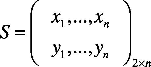
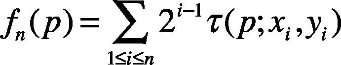
In equation 1, x1 and y1 respectively stand from the point in front and the point behind the number n pair in the sample set. After constructing the BRIEF pattern, all the keypoints can be put in the sample array. The n number of pairs are to be formed. The grayscale values of the two points in each pair are compared. The result is either 0 or 1. Then, the 0 or 1 of each pair is taken to form a group of binary character string and this binary character string is the descriptor of the keypoint. Equation (2) shows the pixel grayscale value of sample pair p. The x is a point in front, and y is the point behind. If the grayscale of the point in front is smaller than that of the point behind, p is 1; otherwise, it is 0. Equation (3) shows the binary descriptor formation process. In that, n is the number of samples, such as 32, 64, 128, 256, or 512. The result of every comparison, 0 or 1, moves leftward and the i–1 bit is accumulated.
2.3Descriptor matching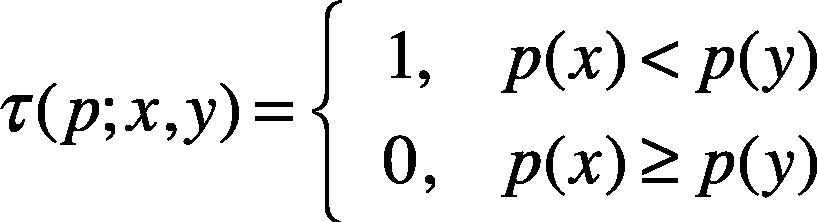
As mentioned in the beginning of this paper, our objective is to identify the corresponding relationship between the template and the target. The explanation above is the preliminary process of finding the keypoints and describing their features to form a set of descriptors to perform the matching.
After the keypoints of the template and the target are transformed into descriptors, matching is performed to identify the corresponding relationship between the template and the target.
Since the descriptors used in BRIEF are binary character strings, XOR can be applied to compute the difference between each pair of descriptors. For example, suppose that the number i group of descriptors taken from an O set of descriptors of the template and the number j group of detectors from the U group of descriptors of the target are respectively 00001111 and 10001001. The result after XOR computation is 1000110. The XOR result is accumulated and 3 is obtained, indicating that the difference of each pair of descriptors is 3. Likewise, all the descriptors are matched to find the pair of descriptors with the smallest distance. Figure 2 shows the matching results between the template and target descriptors.
2.4Feature correspondences
The corresponding results of the template and target descriptors can be divided into correct matches and mismatches. To maintain correctness in subsequent deformation computation, we need a reliable algorithm to reject error matches. Taking the speed and level of difficulty of implementation into consideration, we choose the algorithm applied in Tran, Chin, Carneiro, Brown and Suter (2012)
2.4.1RANdom SAmple ConsensusThe concept behind this algorithm is based on RANdom Sample Consensus (RANSAC), put forward by Fischler and Bolles (1981). As shown in Figure 3, samples are extracted from the lines (black solid line) formed by two random points in the data point set, and the distance between every other data point in the data point set to this line is calculated. If it is smaller than the established distance threshold, it is selected as an inlier (a hollow point), otherwise an outlier (a solid point). The number of inliers resulted from each iterative sampling is recorded. At the end of the computation, the line with the most inliers is the sampling model of this data point set. A number of times of sampling can be determined as the condition for termination of the computation.
2.4.2Rejection of mismatches
The algorithm applied in (Tran, Chin, Carneiro, Brown & Suter, 2012) is to locate the mismatches according to RANSAC.
2.4.3Rotationally invariant descriptorsIn this section, rotationally invariant BRIEF descriptors are introduced. A target in continuous images can have rotation or scaling. The original BRIEF algorithm is not equipped with rotational invariance and, therefore, the algorithm will fail when the target rotates. How the descriptors without rotational invariance become equipped with rotational invariance and the issues entailed will also be explained. The BRIEF algorithm does not calculate the direction of corners. Hence, each of the four corners of the square in Figure 4 can be clearly described with a binary character string. The binary character strings of the four descriptors of the template are 00011, 10100, 01000 and 00000, and the four binary character strings of the target are 00011, 10100, 01000 and 00000. Due to the difference existing in between, the four descriptors for the template and the target therefore can be separated distinctly.

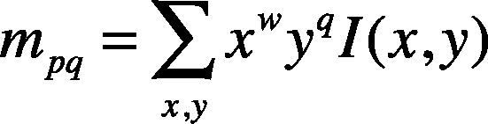
Next, we will discuss how to equip descriptors with rotational invariance. An intensity centroid is applied to calculate corner directions, as shown in equation (4), by computing the vectors of the x and y directions in the corner area. In this paper, a circle with a radius of 15 is defined as the area; x and y respectively stand for the coordinates of a location; I(x,y) is the image grayscale of the coordinates; p and q represent the directions selected. When w = 0 and q = 1, the Y direction is calculated; when w = 1 and q = 0, the X direction is calculated.
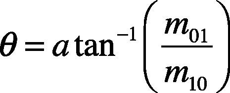
After obtaining the x and y vectors, equation (5) is applied to calculate the trigonometric function of the two vectors, then atan–1 is used to figure out the ratio between m01 vector and m10 vector. Afterwards, radians are converted to degrees to ascertain the direction of each corner. Figure 5 shows the direction of every corner obtained from the above mentioned computation.

After performing direction computation on the corners of the template and the target, we are able to conduct rotation on the sampling model, as shown in equation (6). Except for the changes made to the sampling model, the direction computation approaches adopted in recent years to equip descriptors with rotational invariance, such as BRISK and FREAK, are more or less the same as ORB. Therefore, ORB is used as an example to provide the explanation.
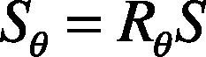
Figure 6 shows that a descriptor with rotational invariance can still have the same binary character string 0110 as the descriptor of the template when the target rotates. However, a new problem appears. The four corners in the template apparently are four different corners, yet they share the same binary character string 0110. As a result, it is impossible to separate the four corners distinctly.

After the above mentioned analysis, we discover that BRIEF descriptors have high differentiation rates, but no rotational invariance and descriptors with rotational invariance have low different rates. Therefore, we work on the problem to come up with an algorithm to solve it.
This algorithm can be divided into two steps:
Step 1. A small number of descriptors with rotational invariance are applied to detect the rotation angle of the match descriptors of the template and the target and the angle that appears the most number of times is the result we want. In this paper, we adopt ORB descriptors to perform the probing.
Step 2. The degree obtained from the probing suggests the likely rotation angle of the target. Then the directional rotation is conducted on the BRIEF sampling model.
By doing so, we are able to give BRIEF descriptors rotational invariance without losing their high differentiation rates. Figure 7 shows how ORB descriptors are applied to probe for the degree of the descriptors on the template and the target in Step 1 and how to rotate the BRIEF sampling model according to the degree obtained in Step 2.
3Tracking initialization
This section elaborates on the second half of the real-time deformation estimation framework that we propose. The first half focuses on detection in order to identify the corresponding relationship between the template and the target in continuous images. In earlier experiments we have discovered that some problems exist if only detection is applied to complete real-time deformation estimation, such as instability of match keypoints on the template and the target. This instability means if the template keypoint coordinates (5, 5) are matched with the target keypoint coordinates (10, 10) at time t, at t+1 they can be matched with the target keypoint coordinates (100, 100) because deformation can occur on the target surface as a result of rotation, scaling and angle of view of the target in continuous images. This makes detection difficult. Since we hope to use these matches as the control points in deformation estimation, the match keypoints have to be stable.
Realizing the problem, we therefore add in the framework a tracking algorithm as a solution. Tran et al. (2012) also mentioned this concept at the end of the paper. Hence, we combine detection and tracking as they can collaborate and complement each other. The purpose of initialization is to provide the keypoints required for the tracking algorithm. In this framework, we adopt the Lucas-Kanade optical flow. These initial keypoints are the match keypoints on the template and the targets detected, but they need to be filtered so that good matches can be retained and the number of matches can be reduced to bring down the overall computation cost. Next, we use Figure 8 to explain the filtering mechanism. Suppose that the continuous images include l number of frames. Starting from the a = 1 picture, the match keypoints on the template are arranged in descending order according to the above mentioned FAST corner responses and the search begins from the corner with a high response toward the neighboring area (the red box) to see if there is any matching keypoint and remove it if there is. Because matches come in pairs, a descriptor from the template and one of the target, the template and the target also need to be removed when the aforesaid matching keypoint removal takes place. Then the same procedure is conducted for the next match until all the matching keypoints are inspected.

After all the matching keypoints are inspected, the filtering mechanism is completed. Figure 8B shows the outcome of filtering in Figure 8A. Then the keypoints from the target are placed in the Lucas-Kanade optical flow algorithm to be the initial tracking points. By doing so, we also define the model of the keypoints on the template and it is applied in subsequent matching computation of keypoints from targets in a > 1 images.
4Experimental resultsWe test the proposed algorithm with the follows data sets. Figures 9A-F show 1|2, 1|3, 1|4, 1|5 and 1|6 stands for the template and 2, 3, 4, 5 and 6, respectively, represent the targets. In other words, 1|2 shows the matching rate of the template and target 2, and so on. The experiment results can prove that the algorithm we propose can indeed solve the problem of lack of rotational invariance, while at the same time keep the high differentiation rate. The 0-360° rotating image in Figures 9A-F are taken from Baker and Matthews (2004).

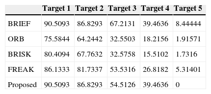
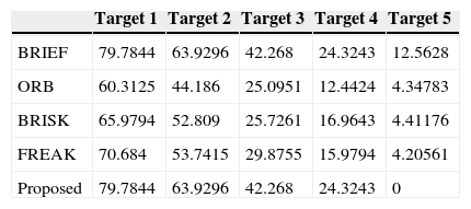
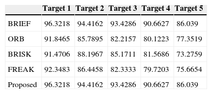
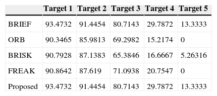
Figures 10-15 show that the algorithm we propose produce rather fine results in handling different problems, whereas the outstanding characteristics of BRIEF are still retained. However, the degree estimated for the Wall and Tree sets turn out to be 0; the low identification rate may have been caused by excessive change of the angle of view of testing images or fuzziness of the details. In addition, we also quantify the test results and present them in Tables 1-6. Figure 16 shows the pure rotation test results can be recognized clearly almost 100% by keypoints.


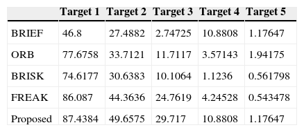
Graffiti test results.
| Target 1 | Target 2 | Target 3 | Target 4 | Target 5 | |
|---|---|---|---|---|---|
| BRIEF | 46.8 | 27.4882 | 2.74725 | 10.8808 | 1.17647 |
| ORB | 77.6758 | 33.7121 | 11.7117 | 3.57143 | 1.94175 |
| BRISK | 74.6177 | 30.6383 | 10.1064 | 1.1236 | 0.561798 |
| FREAK | 86.087 | 44.3636 | 24.7619 | 4.24528 | 0.543478 |
| Proposed | 87.4384 | 49.6575 | 29.717 | 10.8808 | 1.17647 |
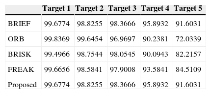
JPG test results.
| Target 1 | Target 2 | Target 3 | Target 4 | Target 5 | |
|---|---|---|---|---|---|
| BRIEF | 99.6774 | 98.8255 | 98.3666 | 95.8932 | 91.6031 |
| ORB | 99.8369 | 99.6454 | 96.9697 | 90.2381 | 72.0339 |
| BRISK | 99.4966 | 98.7544 | 98.0545 | 90.0943 | 82.2157 |
| FREAK | 99.6656 | 98.5841 | 97.9008 | 93.5841 | 84.5109 |
| Proposed | 99.6774 | 98.8255 | 98.3666 | 95.8932 | 91.6031 |
Leuven test results.
| Target 1 | Target 2 | Target 3 | Target 4 | Target 5 | |
|---|---|---|---|---|---|
| BRIEF | 96.3218 | 94.4162 | 93.4286 | 90.6627 | 86.039 |
| ORB | 91.8465 | 85.7895 | 82.2157 | 80.1223 | 77.3519 |
| BRISK | 91.4706 | 88.1967 | 85.1711 | 81.5686 | 73.2759 |
| FREAK | 92.3483 | 86.4458 | 82.3333 | 79.7203 | 75.6654 |
| Proposed | 96.3218 | 94.4162 | 93.4286 | 90.6627 | 86.039 |

Equation (7) is a criterion for assessment of the identification rate template and target keypoints. Recall is a kind of identification rate to estimate the accuracy of matches. True matches are the number of correct matching keypoints on the template and target, and total matches are the total number of the matching keypoints on the template and target. Therefore, the value of Recall is higher indicated that the test results are good.
5Conclusions
In this paper, we propose a feature-based detection algorithm to develop the framework of real-time non-rigid surface deformation detection. The advantages and disadvantages of having and not having rotational invariance are also analyzed and improved computation methods are established in accordance with these advantages and disadvantages to give the feature detection algorithm rotational invariance. The experiments performed have ended up with rather outstanding results. The length of each image tested for non-rigid surface deformation detection is about 50∼80ms and the experiments are conducted with a 2.5GHz desktop computer.