


There is a fast growing interest in new applications for advanced ceramic systems in the field of functional materials and in particular for optical materials. Ceramics are entitled to fulfil the gap between glasses and single crystals in the area of photonic materials. The processing versatility and unpaired resistance to high temperature corrosive environments of some ceramics make them good candidates for such applications. However, the critical dependence of the material optical properties on microstructure makes the deep understanding of the processing conditions even more necessary than before for the fabrication of well ordered, transparent, efficient optical ceramics.
This review is directed towards ceramists interested in new applications. In the paper we address some fundamental aspects of the relationship between processing, microstructure and optical properties that are illustrated with some examples related with transparent ceramics, glass ceramics, luminescence, random lasers, thermo-emissive applications, scintillators and dielectric metamaterials.
Existe un creciente interés en el desarrollo de nuevas aplicaciones basadas en cerámicas funcionales, en particular para aplicaciones como materiales ópticos. Los materiales cerámicos están destinados a cubrir el hueco entre los vidrios y los monocristales en el campo de los materiales fotónicos. La facilidad de procesado junto con su inigualable resistencia en medios corrosivos y de alta temperatura, hacen de las cerámicas buenos candidatos para ser utilizado en las aplicaciones ópticas. Sin embargo, las propiedades ópticas de un material, dependen muy fuertemente de su microestructura. Por ello la fabricación de cerámicas con microestructuras ordenadas, cerámicas transparentes y con eficientes propiedades ópticas requiere más que nunca, conocer profundamente las condiciones de procesado y de su influencia en la microestructura.
Esta revisión está dirigida a ceramistas interesados en nuevas aplicaciones. En el artículo, tratamos brevemente algunos aspectos fundamentales de las relaciones entre procesado, microestructura y propiedades ópticas que hemos ilustrado con algunos ejemplos relacionados con las cerámicas transparentes, las vitrocerámicas, luminiscencia, láseres aleatorios, aplicaciones termoemisivas, centelleadores, y metamateriales dieléctricos.
Advanced ceramics find greater than ever utilization in a wide range of applications. There is an increasing interest for ceramics in the health area, for example in bioceramics1 and in drug delivering systems based on nanoceramics. In the energy field, ceramics are very important not only in the nuclear industry as fuel ceramics or for waste immobilization but also for electricity generation, transport and storage.2Impressive research effort is being done in the study of new electroceramics for Solid Oxide Fuel Cells3 and rechargeable batteries and supercapacitors. In the transport industry it is well known the use of ceramics in spark plug insulators, valves, oxygen sensors or catalyst supports. Furthermore, ceramic magnets such as the hexaferrites, are component part of motors, filters, or in devices for communication technologies.4 In addition to current attention devoted to the synthesis of new ceramic materials new applications require, on the one hand improvement in the traditional processing techniques and implementation of advanced processing techniques on the other hand.5
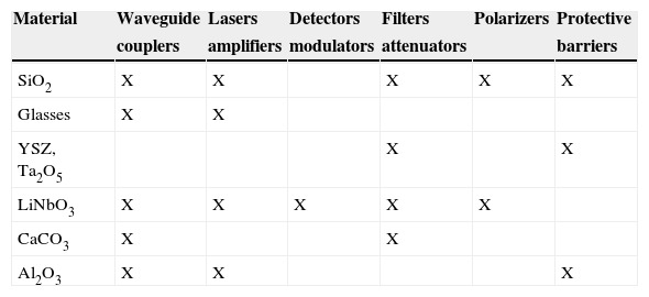
The discovery and development of new processing techniques widens out the range of application of ceramics to the area of optical and photonic devices. Most common optical materials are silica glass, SiO2, and silicon, Si, thin films and substrates together with some semiconductors and oxide single crystals. Optical materials are shaped in the form of fibres, thin films or bulk pieces. Recently, ceramics are taking more and more relevance in optical technology. In Table 1 we present a summary of optical devices made with some oxide materials. One reason for it is that from the point of view of their electronic structure, ceramic compounds are insulators with a wide optical gap very convenient for optical applications. In addition the response of ceramics to light propagation strongly depends on their microstructure. Consequently, its transparency can be adapted by processing conditions.
In addition, compared to single crystals (SC) production of ceramics is less complicated. Accordingly, large ceramic pieces with arbitrary shape and size can be fabricated which is not possible to achieve in the case of SC. Also, ceramic composites can be doped with higher impurity concentration levels than SC made from melt solidification and ceramics with impurity concentration gradients can be easily fabricated. In recent years, the discovery of new sintering techniques allows the production of ceramics with high temperature of melting eluding the need for costly crucibles and contamination. On the other hand, compared to glasses, ceramics have better mechanical resistance, hardness and toughness. In general they also offer higher thermochemical stability than glasses.
Conversely, ceramics are opaque and light hardly propagates through them. Fortunately, as we will see later on this statement is not completely accurate and some ceramics fabricated using small size particles, with homogeneous grain size distribution and very low porosity may present transmittance values close to these of glasses and SC (Fig. 1). Transparent ceramics combining excellent mechanical and good optical properties are used as passive optical components. In particular as waveguides, lenses, mirror supports, optical filters for high power optical beams, etc. Transparent ceramics can be found displacing glasses as a part of armours, house appliances, lamps, LED's, etc. Increasing number of active optical devices incorporate ceramics as phosphors, scintillators, optical amplifiers, in high power lasers and multifunctional materials in general.

In the present paper we compile updated information on the use of ceramics as optical materials. In particular we will briefly describe the fabrication and application of transparent ceramics, of luminescent ceramics and their use in random lasers. Also, we will pay attention to selective thermo-emissive and scintillator ceramics.
Transparent ceramicsCeramics are made of grains with grain boundaries and commonly pores between them. From the point of view of light propagation, light beams are reflected and refracted at material heterogeneities such as grain boundaries and pore walls. As a consequence ceramics perform as transparent, translucent or opaque media depending on the light scattering, which is a function of the ceramic microstructure. First we will focus in the description of the fundamentals describing the light propagation through particulate media.6,7 In these media light undergoes elastic scattering at interfaces. The relevant dimension describing light scattering is given by the ratio between the light wavelength “λ” and the particle dimension “d”.

For very small obstacles, nanoparticles or nanopores, x<<1 and light diffusion is well described by Rayleigh scattering theory. For a small particle of refractive index “n” in air, the scattering cross section is given by
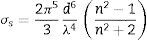
Eq. 2 determines that for x<<1 the scattering cross section is stronger for the short wavelengths and explains for example, the blue-sky caused by the presence of small particles or gas molecules in suspension.8 This kind of scattering might be also present in SC, glasses or ceramics with nanopores (d≈50nm).
For x≈1 the scattering intensity depends on scattering direction and particle size and shape. This effect can be well described by Mie theory in the case of spherical particles. The scattering cross section does not depend on light wave-length (white clouds) unless light absorption due to resonance effects would be present. This is for example the case of colloidal size spherical Cu metallic particles producing lustre effect in ceramics because of the surface plasmon resonance absorption.9 For x>>1 the scattering is strongly directional and dependent on the particle shape. This is the case of the geometric scattering.
In a dense and high purity ceramic the main light scattering sources are the surface, the grain boundaries and the pores. Consequently, the transparency of the ceramic depends on their relative density hence on the ceramic processing conditions. However, there is the question of how can we quantitatively measure the transparency of a translucent body, as is the case of ceramics? There is not a trivial answer to this question. Everybody has experienced with the fact that a translucent material such as a plastic film, may transmit a good image when it is close to the object, for example touching it, but not when distant from the same object. Whole determination of the transmittance properties of a ceramic requires at least three measurements as indicated in Figure 2. Total forward transmission (TFT) and total reflection (TR) are measured with the help of an integrating sphere whereas real in-line transmission (RIT) can be estimated with a conventional spectrometer. RIT is usually the relevant magnitude for most optical applications.
 Total transmission, total reflectance, c) in-line transmission (RIT).")
The effect of microstructure in the RIT of a ceramic for x≤1 can be explained using the Raleigh-Gans-Debye solution to the Mie problem (small optical contrast Δn) where RS is the sample surface reflexion, r the radius of the scatters assumed to be spherical and d the sample thickness.
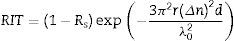
Clearly, to obtain transparent ceramics it is necessary to have a material with small grains and few pores (ideally relative densities of 99%). In composites small refractive index contrast between components helps to increase the transparency. In the case of single component ceramics optically isotropic materials as cubic ceramics are preferred to anisotropic materials because the index contrast between grains is much smaller in the former.
Fabrication of ceramics with small grain size and high relative densities is usually accomplished by using nano powders as starting materials and low temperature presintering conditions to avoid grain growth. The control of the green body porosity and of sintering atmosphere is of great importance for a dense ceramic. Also the presence of impurities may modify the grain growth. An example of the later being the case of MgO dopants used for transparent Al2O3 synthesis.10
The role of the sintering atmosphere is exemplified by the sintering of translucent Al2O3 in a hydrogen or oxygen atmosphere in contrast with the opaque bodies obtained when sintering is performed in nitrogen, air or argon atmosphere. In general a good sintering atmosphere is that in which the gases present a good solubility and high diffusivity in the solid to be sintered.11
Different sintering methods are used in the transparent ceramic preparation.
- •
Stress-assisted sintering is a technique where external stresses are applied. External compressive stresses produce additional driving forces for mass transport leading to increased densification rates and decreasing grain growth dynamics.12 In hot pressing (HP) the stress is applied uniaxially through a piston and the microstructure may show preferential orientation. That can be avoided by hot isostatic pressing (HIP) where the powder is placed in a membrane that is under isostatic stress using a high-pressure gas.
- •
Field-assisted sintering (FAST) techniques use electric fields to densify materials in a short time maintaining the ultrafine powder size. Sometimes called Spark Plasma Sintering although the production of any plasma during the process is under debate, the sintering is also assisted by moderate uniaxial compressive pressures.
In summary, transparent or translucent ceramics are near to fully dense, density >99.0% of theoretical, polycrystalline materials with small grain size, d<100nm, much smaller than the wavelength of visible light. Some examples of transparent ceramics: Al2O3, YAG, ALON (Al23O27N5), Mg-spinel (MgAl2O4; Fig. 3), ZrO2:Y2O3, Y2O3:ThO2, etc.
Glass ceramics
Glass ceramics constitutes by itself a class of transparent ceramics produced by controlled crystallization of glasses. They contain a variable but elevated amount of crystallites, between 30 to 90vol%, embedded in the amorphous matrix. Their properties can be almost completely controlled by composition and processing leading to outstanding behavior of glass-ceramics when compared with conventional glasses or single crystals. These properties more frequently include, zero porosity and near to zero thermal expansion coefficients inducing the high resistance to thermal shock, high mechanical resistance and toughness of glass-ceramics. High chemical and thermal stability establish the wide panoply of applications of glass-ceramics from cooktops to supports for big telescope mirrors.
In addition, the transparency of glass ceramics can be modified by the addition of impurities that can also transform them into special luminescent materials. As the luminescent center can be located either in the glass matrix or in the crystalline phase, the emission spectra of the glass-ceramic can be tailored somehow. In addition to the mechanical and optical applications13 other functional activity such as electrical conduction and bioactivity has also been incorporated to glass ceramics.
Glass-ceramics are fabricated in two steps. First casting of the melt produces the glass that in a second step is recrystallized with the help of nucleation aids. Devitrification by the crystalline grain nucleation and growth procedure requires the presence of many and homogeneously distributed nucleation centers. This procedure produces fairly homogeneous spherical shape crystallites. Devitrification can be also produced by spinodal decomposition of a glass. In this case the crystallites use to be of dendritic morphology.
Glass-ceramics can be also obtained from glasses produced by low temperature methods as sol-gel. In this case the presence of impurities in the glasses can be a problem for some optical applications. If the inclusions are of nanometric size, and there is a low refractive index contrast between the crystalline and the amorphous phase, the material is transparent (Fig. 3).
One commonly used commercial glass-ceramic is LAS, the acronym designing a commercial glass-ceramic that stands for the composition Li2O/Al2O3/SiO2 with Na2O, K2O and CaO as glass formers and ZrO2 and TiO2 as nucleation vehicles. MAS and ZAS glass ceramics are obtained by substitution of the Li2O for MgO and ZnO respectively.
From the point of view of the microstructure these glass-ceramics consist of an alumino-silicate glass with nano-inclusions of a solid solution of β-quartz. The crystalline phase is responsible for the enhanced thermomechanical properties of glass-ceramic.
Luminescent ceramicsLuminescence is produced when the high energy levels of an electronic system, previously excited by light, electrons, X-ray, phonons or another excitation source, decay radiatively into the ground electronic state by emitting light. Most luminescent materials take benefit of the presence of a wide optical gap in its electronic band structure or alternatively, of the existence of localized electronic states within the gap associated to the presence of defects or impurities. The most common optically active impurities are transition metal or rare-earth ions. The intensity of the emission bands depends on the ion environment, the ion concentration and on the excitation. As a general rule, transition metal ions produce broad absorption and emission bands whereas rare-earth ion optical transitions are narrow. This is due to the strong electron-vibration coupling between the optically active electron d-levels in the case of transition ions as opposite to the f-level screening in the case of rare earths. Most commonly the ion electronic states are excited by light that nonradiatively decay down to an electronic level with a large deexcitation gap, the emitting level. This light absorption and emission process is illustrated in Figure 4 for the case of the Eu3+.
 and the luminescence bands (right).")
Ceramics doped with optically active ions are commonly used in the fabrication of phosphors for fluorescence lamps. For example, the halophosphate (Ca5(PO4)3(F,Cl):Sb3+, Mn2+) has been used for “white” light, and more recently, the Tb3+, Ce3+:LaPO4 for green and blue light respectively and Eu3+:Y2O3 for red. For Cathodic Ray Tubes (CRT) television and computer colour screens the electroluminescent ceramics for the three elemental colours were, Pb:CaWO4 for blue, Mn:ZrSiO4 for green and Eu:YVO4 for red colour.
Tuning up-conversion in eutectic ceramicsEutectic ceramics constitutes one special case of composite materials with a highly ordered microstructure resulting of the directional solidification from melt. The constituent phases are single crystalline rods or lamellae of micrometer dimensions. These materials may combine the best properties of single crystals; transparency, light guiding, optical activity, with the best mechanical properties of ceramics.14
An illustrative example of the enhanced optical properties that can be found in eutectic ceramics is the accomplishment of light up-conversion effect (transformation of infrared light into visible light) in eutectic ceramics. The effect has been observed, for example, in the Calcium Stabilized Zirconia Calcium Zirconate eutectic doped with Erbium. This is a lamellar eutectic which microstructure is depicted in Figure5. As indicated in Figure 6a the light up-conversion takes place by means of a two-photon (λ=800nm) excitation into the 4F9/2 excited state of Er3+ followed by red or green emission. Luminescence bands for two different excitation wave-lengths are depicted in Figure 6b. Interestingly, any of the two component phases, CaZrO3 or CaSZ can be selectively excited by just slightly tuning the excitation light as the absorption bands of Er3+ in these crystals are a little shifted from one another. In this way the dominant emission is either green or red as seen in Figure 6b.15
Random lasers Electronic levels of Er3+ showing a possible model for the two-photon IR absorption (blue lines) and the green and red emissions. b) Green and red emissions excited at the wavelengths indicated in the figures.")
Laser emission is based in the stimulated emission of a luminescent system. Population inversion is needed in order to get significant stimulated emission which otherwise means that non-radiative losses are compensated by efficient and intense pumping. In order to obtain light amplification most of the lasers use optical resonators and low losses light amplifying media. However, highly disordered optical materials can achieve light amplification. They constitute what is now called Random Laser materials. The base of random lasers is the achievement of multiple light scattering with gain. For example, a powder sample consisting of microspheres coated with a dye can be pumped to get the inverse population. Then the microspheres scatter the light producing the amplification of the light. The light propagation is an amplified random walk leading to incoherent amplified light beams.
A typical random laser is made of fine ZnO particles dispersed in a laser dye. The emission excited by a laser in the semiconductor gap excites stimulated emission in the medium. The losses associated to multiple scattering compete with the medium gain and above a given excitation intensity threshold light amplification is observed. Random lasing has also been recently reported in crystal powders (LCP) and in highly porous materials. In these cases the crystalline grain and the pore are the optical cavities where the stimulated light is amplified.
In Figure 7 we illustrate the first observation of the LCP effect at RT made by J. Fernandez and R. Balda group in the University of Basque Country (Bilbao).16 It can be appreciated that the 1.06μm emission of Nd3+ is dramatically narrowed above a given laser power threshold and indication of the local mode amplification in this crystalline powder sample. The near future challenges for random lasers are to combine electron localization with scattering properties is such a way that only one emission transition could be amplified. There is also the aim of systems with electrical excitation that could be of use in displays.
:LuVO4 powder crystal obtained at pumping energies below (5mJ blue) and above (24mJ red) the laser threshold (with permission from Azkargorta et al.16).")
– Normalized emission spectra from Nd3+ (3%):LuVO4 powder crystal obtained at pumping energies below (5mJ blue) and above (24mJ red) the laser threshold (with permission from Azkargorta et al.16).
One key advantage of ceramics over other materials is the thermochemical resistance that makes them to be irreplaceable in high temperature applications. One such application is as selective thermal emitters in thermo-photovoltaic cells. These thermal emitters transform thermal energy (from waste heat, solar or other sources) into useful photonic energy. In addition to the unpaired resistance to high temperatures in air of some oxide ceramics they present a lower thermal emission in the far infrared (FIR) range of the spectrum than metals, even than refractory metals. On the other hand, the emission of selective thermal emitters must be large in the spectral band where photovoltaic cells are more efficient. Rare-earth containing high temperature ceramics fulfill these requirements, thermochemical stability and selective emission. Both fabrics and porous ceramics made of Rare Earth Oxides or Rare Earth Aluminum Garnet have been chosen for thermo-photovoltaic devices.17
Recently, Al2O3-RE2O3 (RE= rare earth) directionally solidified eutectic ceramics were proposed for this application,18,19 grounded by their better resistance to thermal shock than conventional ceramics. In Figure 8 the thermal emission of the Al2O3-Er3Al5O12-ZrO2(Er2O3) ternary eutectic at 1600°C is given. The emission spectra are a superposition of the blackbody emission and that of Er3+ in the Er3Al5O12 garnet (EAG) and Erbia stabilized cubic zirconia phase (ErSZ). The high selectivity degree of the emission can be appreciated as the spectra features the characteristic emission bands of Er3+ more than that of the black body radiation. Still under research, the way in which light propagates into these composites, which depends on microstructural size and probably on phase alignment, has an influence on the efficiency of the thermal emission (see Fig. 7 in Mesa et al.19). As shown in Mesa et al.,19 thermal emission at 1.55μm, and apparently also selectivity, is larger in the Al2O3-Er3Al5O12 binary eutectic solidified at 750mm/h (size of the EAG phase 335nm) than in the one solidified at 25mm/h (size of the EAG phase 2.3μm). Tailoring the light scattering (that is, microstructure) appears to be crucial in the design of the optimized material.
 and Al2O3-ErAl2O3-ErSZ (AEZ) with coarse (AE25 and AEZ25) and fine (AE750 and AEZ1200) microstructures measured at 1600°C from Mesa et al.19")
– Selective emission spectra of eutectics Al2O3-ErAl2O3 (AE) and Al2O3-ErAl2O3-ErSZ (AEZ) with coarse (AE25 and AEZ25) and fine (AE750 and AEZ1200) microstructures measured at 1600°C from Mesa et al.19
Scintillators are materials that convert the energy of ionizing radiations such as: X-rays, α, β and γ-X-rays and even neutrons into light. Emitted light is transformed into electrical signal by photovoltaic systems. The energy efficiency of a scintillator is given by:

γ refers to the efficiency of the electron-hole pair generation by the radiation. S is the efficiency of energy transfer from the electron-hole pair to the luminescent ion and Q is the emission efficiency. High-energy efficiencies are obtained in high-density materials with efficient luminescence. This is achieved in materials made of heavy metal oxides or halides. Up to date most of the scintillator devices are made of transparent single crystal materials. For example, CsI:Tl, CdWO4, Bi4Ge3O12. However, oxide single crystals are fragile and difficult to grow in large dimensions. Recently, ceramic plates of (Y,Gd)2O3:Eu and Gd2O2S: Pr, Ce are used instead.
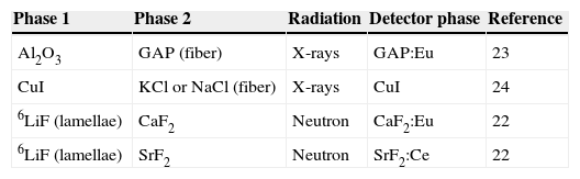
Phase separated scintillatorsUnidirectional light guiding in the high refractive index phase of a well aligned, directionally solidified eutectic ceramics, as show above in Figure 5, has been further exploited in a new discovery termed as “phase separated scintillators”. Basically, scintillators consist on a slab of radio-luminescent material with one surface exposed to radiation whereas the emitted light is detected through the opposite surface. Sensitivity to radiation is provided by eutectic compositions comprising crystal phases suitable for radiation detection.20 Certain combination of material properties is crucial to have the desired function.21 First, a two-phase composite material with a good alignment of phases along the direction of light propagation is needed. Second, phase size must be comparable or larger than the optical wavelength together with an appropriate refractive index contrast, so that geometrical scattering favors propagation of light parallel to the interphase surfaces and can transmit images from one side of the slab to the other. Third, at least one of the phases should have good stopping power for the particle to be detected. For neutrons this is achieved, for example, by a 6Li-containing phase,22 which interacts strongly with thermal neutrons to produce g-rays. For X-rays detection, large atomic number atoms are required in the component phases.21,23 Finally, efficient luminescent species that are excited by X-rays or g-rays gives rise to luminescence that is driven to the detector array by the light-guide eutectic ceramic. Ohahsi et al.24 used the fibrillar Eu3+ doped Gd2O3-Al2O3 binary eutectic to demonstrate that directionally solidified eutectics with rods of larger refractive index than the matrix (GAP:Eu3+ fibers in Al2O3 matrix) have better spatial resolution than conventional CsI:Tl columnar scintillator films. In Table 2 some binary eutectic systems that have been postulated for scintillator devices are given.

Metamaterials are defined as artificial materials, not found in nature, with a microstructure smaller than the wavelength of the electromagnetic field showing unconventional electromagnetic properties such as negative refraction index materials, cloaking effects, and giant dielectric constants. Metamaterials are structured materials that combine metals and dielectrics, polymers, or magnetic oxides and are currently fabricated by electron lithography, focused ion beam milling, and other nanotechnologies. In the long wavelength regime, they can be considered as homogeneous media, and their electromagnetic properties rely on those of the basic constitutive structure. Recently all-dielectric metamaterials are being experimentally and theoretically studied for low frequency applications. It has been proven that resonant structures with large electric and magnetic activity in the THz range can be produced using large permittivity ceramic materials.25
Controlling the Mie-resonance in the THz to VIS range requires a precise control over the shape, size and distribution of the particulate material inside an appropriate matrix in the micron and submicron range. Moreover, large dielectric constant materials in the appropriate spectral range are required to effectively achieve true metamaterial response. Phonon-polariton resonances, present in most insulators in the MIR or FIR (THz range) fulfill these conditions just below the phonon-polariton resonance, and thus offer the opportunity to tailor THz electromagnetic waves.
In order to model the electromagnetic behavior of these metamaterials different approximations can be used depending on the dielectric contrast and size of the constitutive elements. When the phonon-polariton constitutive units have sizes much smaller than 1μm and are disperse, very simple effective medium models such as the Maxwell-Garnett reproduce satisfactorily the electromagnetic behavior of the material.26 Consequently a ceramic composite formed by aligned microwires of a polaritonic material inside a dielectric matrix is a filter polarizer at frequencies near or inside the phononpolariton gap of the rods. Hyperbolic dispersion, superlensing effects or epsilon near zero based transmission has been predicted for such structures.27 For larger microparticle sizes, Mie resonances contribute notably to the optical constants and regions of negative permeability as well as negative permittivity have been deduced from experiments in whiskers of large dielectric constant materials such as SiC.28
The manufacture of materials with such a degree of microstructural control is not without difficulties. Apart from bottom-up approaches described above self-assembling methods such as ceramic colloidal templating, or directional eutectic solidification for unidirectional structures has been developed. The positive aspect here is that, as has already been said, directional solidification of eutectics is a self-organized process leading to highly textured materials where realization of microstructures with geometries suitable for metamaterials fabrication is possible. For example, the existence of split-ring resonator-like (SSR) crosssectional features has been confirmed in the SrO-TiO2 directionally solidified eutectic ceramics.29 Moreover, the SRR structure is the first demonstrated example of a negative refraction index metamaterial.
This later approach has been also explored with alkali halides.30Figure 9a shows an optical micrograph of a NaCl-LiF and Figure 9b a SEM micrograph of a ternary NaCl-LiF-CaF2 directionally solidified eutectics. The latter has been water-etched to better reveal the microstructure. The microstructure of NaCl-LiF consists of LiF rods (dark) embedded into a NaCl matrix. LiF rods occupy 25% vol of the composite in the left-hand-side picture. The ternary (right) contains LiF (grey) and CaF2 (bright) irregular cylinders embedded into NaCl matrix. The optical properties of reference alkali halide directionally solidified eutectics have been measured, which coincide with the expected theoretical behavior for these materials.31
 Optical transmission micrograph of a NaCl-LiF eutectic transverse cross-section. LiF rods (dark) embedded into a clear NaCl matrix. b) SEM micrograph of a ternary NaCl-LiF-CaF2 directionally solidified eutectic transverse cross-section. The grey phase is LiF, CaF2 is bright and the etched matrix is NaCl.")
– a) Optical transmission micrograph of a NaCl-LiF eutectic transverse cross-section. LiF rods (dark) embedded into a clear NaCl matrix. b) SEM micrograph of a ternary NaCl-LiF-CaF2 directionally solidified eutectic transverse cross-section. The grey phase is LiF, CaF2 is bright and the etched matrix is NaCl.
In optical materials the most relevant parameters are the magnitude of the optical gap Eg and the microstructure size in comparison with the wavelength. In particular the quotient d/λ tell us the relative weight of the microstructure on light propagation.
Traditionally, most optical materials have been wide optical gap, monolithic and dense glasses (oxide, fluoride glasses, etc.) semiconductors and single crystals. But ceramics, made of wide gap materials can increase the panoply of optical materials for the reason of the simpler fabrication and better thermo-mechanical and chemical resistance.
However, incorporation of ceramics to the optical materials field needs implementation of the ceramics processing methods in order to achieve the right microstructure adapted to the foreseen optical application. Today, film deposition techniques, nano and micro assembly, colloidal processing, directional solidification, etc. let us to fabricate ceramics with the microstructure control required for photonic applications.
We want to thank MINECO (Spain) financing: MAT2012-30763 and MAT2013-41045-R programs. Also to the members of the Procacef group for their contributions to the material compiled in this paper.

