


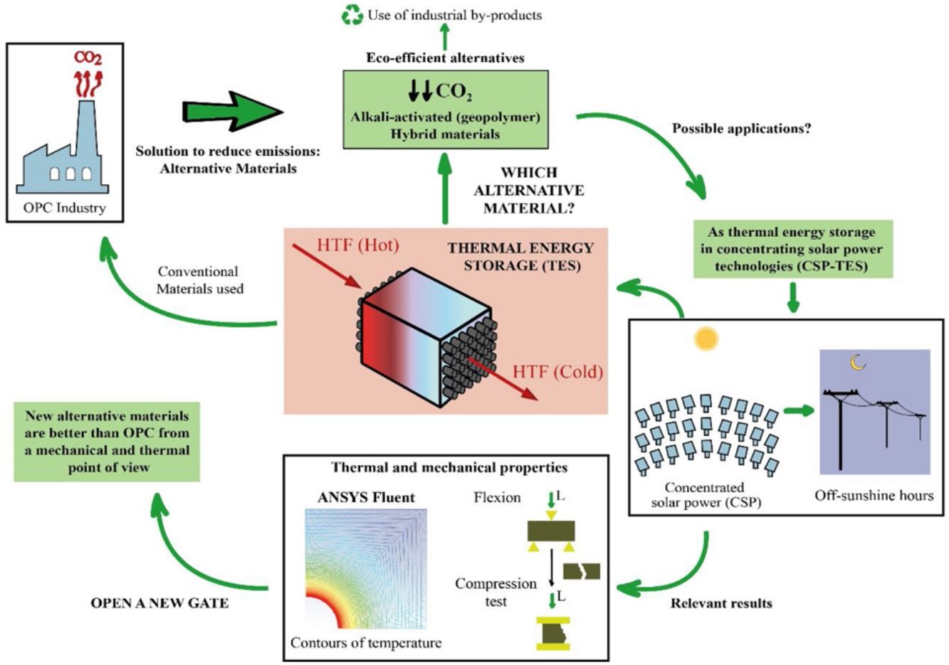
This study is part of the research line that sees it necessary to develop materials that are alternatives for Portland cement (PC), using industrial by-products such as blast furnace slag and fly ash. This line arises because of the serious environmental consequences suffered by our planet throughout many decades, which have led the cement industry to reduce the amount of CO2 emitted in the production of PC, since it is a highly polluting process. The chemical and physical properties of the materials were studied. In this way, the study of the thermal properties is interesting to test the feasibility of the mortars to use them as solid media to storage thermal energy, since most of the research focus on the thermal properties of concrete is oriented toward fire resistance. Storing solar thermal energy improves the operation of solar power thermal plants. It is being studied that the use of concrete (composed of PC) contributes efficiently to concentrated solar power (CSP) technology. To avoid the use of PC due to environmental concerns, alkaline-activated mortars are manufactured with blast furnace slag using alkaline solutions such as sodium hydroxide (NaOH) and commercial sodium silicate (SiO2/Na2O=0.8), as well as hybrid mortars using 80% fly ash or blast furnace slag and 20% PC. After experimental analysis and a simulation to measure the conduction within the mortars through a commercial Computational Fluid Dynamic software (CFD, ANSYS Fluent), it can be concluded that the mechanical and thermal properties of most of the alternative mortars manufactured in this study are better than the ones obtained in the PC. Most notably, the slag alkaline-activated mortar increases those properties significantly.
Este estudio se enmarca en la línea de investigación que ve necesario el desarrollo de materiales alternativos al cemento Portland (PC), utilizando subproductos industriales como las escorias de alto horno y las cenizas volantes. Esta línea surge debido a las graves consecuencias medioambientales que ha sufrido nuestro planeta a lo largo de muchas décadas, que han llevado a la industria cementera a reducir la cantidad de CO2 emitida en la producción de PC, ya que es un proceso altamente contaminante.
Se estudiaron las propiedades químicas y físicas de los materiales. Así, el estudio de las propiedades térmicas es interesante para comprobar la viabilidad de los morteros para utilizarlos como medios sólidos de almacenamiento de energía térmica, ya que la mayor parte de las investigaciones centradas en las propiedades térmicas del hormigón están orientadas a la resistencia al fuego. El almacenamiento de energía térmica solar mejora el funcionamiento de las centrales termosolares. Se está estudiando que el uso del hormigón (compuesto de PC) contribuye eficazmente a la tecnología de energía solar concentrada (CSP). Para evitar el uso del PC por motivos medioambientales, se fabrican morteros activados con escoria de alto horno utilizando soluciones alcalinas como el hidróxido de sodio (NaOH) y el silicato de sodio comercial (SiO2/Na2O=0,8), así como morteros híbridos que utilizan un 80% de cenizas volantes o escoria de alto horno y un 20% de PC. Tras el análisis experimental y una simulación para medir la conducción dentro de los morteros mediante un software comercial de dinámica de fluidos computacional (CFD, ANSYS Fluent), se puede concluir que las propiedades mecánicas y térmicas de la mayoría de los morteros alternativos fabricados en este estudio son mejores que las obtenidas en el PC. En particular, el mortero activado alcalinamente con escoria aumenta significativamente esas propiedades.
Due to the serious environmental threats that our planet has been experiencing for numerous decades, climate change is not just a problem for the future, but one that we are currently facing. To try to halt this change, the Paris climate conference (COP21) was organized to prevent its negative effects. In addition, because of this notorious threat, the Global Climate and Health Summit (COP25) was held in Madrid in 2019 to accelerate the Paris Agreement. All of this reflects the importance of decreasing energy consumption and the amount of CO2 emitted into the atmosphere, especially in industrial processes. More specifically, the cement industry consumes a large amount of fossil fuel, which is approximately 12–15% of industrial energy consumption [1]. Thus, the present study focusses on new alternative materials that replace Portland cement (PC) using industrial by-products, such as blast furnace slag and fly ash. The cement industry contributes detrimentally to climate change by emitting polluting gases such as SO2, NOx and, especially, CO2, which is one of the main greenhouse gases [2]. In particular, in the production process of PC in solid state at high temperature, the cement industry emits between 7 and 9% of the CO2 global emissions. This high percentage is related to the emissions generated, about 0.7–0.9 tons of CO2, when a ton of cement is produced [3]. The origin of these emissions is mainly produced by the limestone decarbonization, which is the main component of raw cement, and from burning fossil fuel in rotary kilns. To avoid the aforementioned problems, this study proposes development of sustainable and eco-efficient cementitious materials as an alternative to PC [4].
One of the alternatives available to PC is the use of alkali-activated aluminosilicate materials, called geopolymers or alkaline cements [5–7]. These systems use precursors that are based on aluminosilicates, which can be natural products (such as kaolinite and other calcined clays) or by-products of industrial processes like fly ash (waste from thermal power plants) or blast furnace slag [1]. These aluminosilicate materials generate different conglomerates after their activation with strong alkaline solutions (such as NaOH or sodium silicates). The geopolymers stand out because they do not require high-energy consumption to be produced and by extension, they do not release a large amount of emissions in the manufacturing process. In line with these ecofriendly characteristics, the alkali-activated systems use waste from other industries that would otherwise end up in dumps. Furthermore, they present good cementing properties and high durability and are used in many countries as precast material [8–11]. However, they also have disadvantages, for instance, their use of alkaline solutions. As an example, the preparation of 1kg of sodium silicate emits 1.5kg of CO2 into the atmosphere [9].
One way to mitigate these disadvantages is by finding alternative materials for alkaline activated ones. These new environmentally friendly materials are called hybrid cements [12,13]. Hybrid cements use a very low PC content (less than 30%) and a high content of aluminosilicate materials (for example fly ash, slag or dehydroxylated clays) as raw materials. For their hydration, they need water and an alkaline activator (normally soft alkaline salts are pre-mixed with the precursor. A solid activator is easier to handle than an alkaline solution). These cementitious materials would combine good mechanical properties with low energy consumption and low CO2 emissions, and in addition, they avoid the use of alkaline solutions.
These alternative materials were studied from a physical and chemical point of view. Specifically, thermal properties of the mortars were analyzed to test their viability as thermal energy storage (TES) materials, which is interesting due to the few scientific articles that exist, since the most research is only focus on fire resistance [14].
The use of concrete as TES is being studied in the recent years at low temperatures, for example to use them in buildings [15,16] and also, at high temperatures, such as in solar power thermal plants [17–19]. The improvement of the storage in concentrated solar plants (CSP) is really attractive to reduce costs, to enhance the operational efficiency of a renewable energy and to solve one of the most important issues; the mismatch between the energy demand and solar resource availability.
The storage of thermal energy makes dispatchability possible. This means that electricity can be dispatched on demand when the source is not available (during off-sunshine hours). In a CSP-TES plant, there are three major operations (Fig. 1): solar field and receiver, thermal storage, and power block.

The CSP technology concentrates solar radiation into a receiver. This thermal power is used as a thermal energy source in the steam generator to produce the steam needed in a Rankine cycle power plant for electricity generation [20]. The meteorological effects and off-sunshine hours can compromise the availability of the solar resource. TES help to reduce these effects. TES is broadly accepted as the best strategy to use in solar power plants, due to its wide range of working temperature (120–600°C) similar to the temperature operating range of the different heat transfer fluids (HTF) used in these concentrated solar power plants [18,21]. The TES systems have three strategies for energy storage: Sensible heat storage, latent heat storage and chemical heat storage. For the sensible heat storage systems, which can be liquid or solid, there are some relevant parameters to consider when deciding on their material: thermal conductivity, specific heat, density, porosity, vapor pressure, operational temperatures, heat losses, stability with temperature and cost.
The sensible TES in a solid media such as concrete is a useful and attractive technology due to low manufacturing cost, high thermal conductivity and high heat capacity [22–24]. Furthermore, their features include easy handling and structural stability. Hence, in many sensible heat storage systems, PC has been used to create the blocks where the thermal energy is stored. For charging and discharging these blocks (Fig. 1 – sensible heat storage, solid media), a HTF that passes through it at high temperature is necessary. So, the materials that composed those blocks must count with high thermal conductivity values in order to charge the storage media quickly. The insertion of multi-tubular cavities in the concrete where the HTF flows is a good option to enhance the performance of the solid storage system [25].
Because of the PC disadvantages that are already mentioned, this work proposes development of new sustainable materials (mortars) to replace PC, especially, in those applications where the thermal properties are linked, such as a solid storage material in solar power thermal plants. To achieve this objective, alkaline-activated mortars were manufactured with blast furnace slag using two different alkaline solutions; one with sodium hydroxide (NaOH) and the other with commercial sodium silicate or waterglass (SiO2/Na2O=0.8). In the case of hybrid mortars, they were composed of almost 80wt.% fly ash or blast furnace slag and almost 20wt.% PC and solid sodium sulfate was used as a solid activator. Water was used to hydrate the systems. Mortars with PC were also manufactured in a conventional way as reference samples.
Experimental procedureMaterialsTo manufacture 7 different mortars, three raw materials were used. The reference sample was manufactured using an PC-type I (CEM-I 42.5R) supplied by “Cementos Portland Valderrivas”. The alternative mortars, hybrid and alkali-activated mortars, were composed of by-products of industrial processes. Specifically, the precursors were blast furnace slag (SLAG) supplied by ENSIDESA factory (Avilés, Spain) and fly ash (FA), which comes from the Puentenuevo thermal power plant (Córdoba, Spain).
Sample preparationThe raw materials were used in different quantities depending on the type of mortar (see Table 1). Three types of mortars were prepared:
- 1)
Group I: PC mortars. These reference samples contain 450g of PC with a liquid/solid ratio (L/S) of 0.5.
- 2)
Group II: Alkali-activated slag mortars. Two different alkali-activated mortars were manufactured. Both contain 450g of slag, but they differ in the solutions used: NaOH 4M solution (L/S ratio of 0.5) and a sodium silicate solution (waterglass) (L/S ratio of 0.55). To dilute the latter solution, water was used and NaOH was added to achieve a SiO2/Na2O ratio of 0.8.
- 3)
Group III: Hybrid mortars. Four different hybrid systems were studied. They contain a mixture of PC and slag or fly ash depending on the system. Furthermore, 3 or 5% of Na2SO4 was added to accelerate their hydration (these low percentages were added according to data provided in the bibliography [26]). Systems with a 3% of Na2SO4 in its composition contain a 78.5wt.% of by-product, while those that count with a 5% of Na2SO4, have a 77.5wt.%. The L/S ratio of those systems was 0.37 as it can be observed in Table 1.
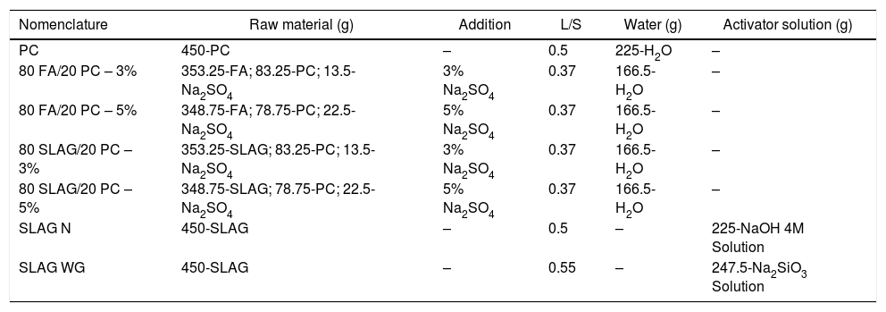
Composition of the different mortars.
| Nomenclature | Raw material (g) | Addition | L/S | Water (g) | Activator solution (g) |
|---|---|---|---|---|---|
| PC | 450-PC | – | 0.5 | 225-H2O | – |
| 80 FA/20 PC – 3% | 353.25-FA; 83.25-PC; 13.5-Na2SO4 | 3% Na2SO4 | 0.37 | 166.5-H2O | – |
| 80 FA/20 PC – 5% | 348.75-FA; 78.75-PC; 22.5-Na2SO4 | 5% Na2SO4 | 0.37 | 166.5-H2O | – |
| 80 SLAG/20 PC – 3% | 353.25-SLAG; 83.25-PC; 13.5-Na2SO4 | 3% Na2SO4 | 0.37 | 166.5-H2O | – |
| 80 SLAG/20 PC – 5% | 348.75-SLAG; 78.75-PC; 22.5-Na2SO4 | 5% Na2SO4 | 0.37 | 166.5-H2O | – |
| SLAG N | 450-SLAG | – | 0.5 | – | 225-NaOH 4M Solution |
| SLAG WG | 450-SLAG | – | 0.55 | – | 247.5-Na2SiO3 Solution |
All systems were prepared with the same cementitious material:sand ratio (1:3).
First, to homogenize the hybrid mortars, a powder mixing turbine (System Schatz T2F) was used for 15min. Then, the mortars were prepared according to the UNE 196-1 standard. The liquid/solid ratio (L/S) was decided following the UNE EN 1015-6 standard which establishes that mortars must have the same workability [9].
After the mixing, the mortar was poured into rectangular molds (4cm×4cm×16cm) to facilitate studying the samples from a mechanical point of view. The mix was also poured into a cylindrical silicone mold with a diameter of 5cm and a thickness of 0.5cm to study the thermal conductivity [27,28]. To improve the mortar distribution in the rectangular mold, the Proeti automatic compactor was used, which facilitates the compaction by applying 60 strokes in 1min according to the UNE 196-3 standard. In the cylindrical mold, the compaction was made manually due to the small dimensions.
In the last step, the samples were placed on a support in a container with water to provide a humid climate (99% of relative humidity) during 28 days of curing at room temperature (22°C). When samples were extracted from the containers, they were immersed in acetone and ethanol to remove any residuals of liquid that could contain and stop their hydration process.
MethodsThe powder of the raw materials was studied by X-ray Fluorescence (XRF) using the SPECTRO XEPOS AMETEK spectrometer with a 50W/60kV X-ray tube generator working in a helium atmosphere. X-ray laser diffraction was used to analyze the particle size, distribution, and the cumulative percentage of each type of raw material using the Mastersizer 2000 diffractometer with Hydro2000SM dispersion unit, model ADA2002. Ethanol was used as the particle dispersant and a stirring speed of 2000rpm was applied. Also, to study the mineralogical and microstructural characterization, the Fourier transform infrared spectroscopy (FTIR-ATR) and X-ray diffraction (XRD) were used. In the first analysis technique, the Nicolet 6700 spectrophotometer from Thermo FTIR Scientific was used. To manufacture this test sample, 1mg of the raw material was mixed with 300mg of KBr, and the mix was compacted. Each FTIR spectra was recorded after running 64 scans in the 4000–400cm−1 range. Regarding the XRD technique, the D8 ADVANCE diffractometer and manufactured by BRUKER-AXS were used. The diffractometer has a 4-kW high voltage generator, an X-ray tube with a Cu anode, which works at 40kV and 50mA, with an automatic divergence slit, a graphite monochromator and an automatic sample changer. To achieve a flat surface in the samples, the powder used had a particle size less than 45μm. Measures were obtained using Cu-Kα1, α2 radiation with a 2θ interval between 5° and 60°, a 0.02 step/size and a 0.5s time/step.
Regarding mortars and their analysis, total porosity and pore size distribution were determined by Mercury intrusion porosimetry (MIP) with a Micromeretics AutoPore IV 9500 analyzer, which is able to exert pressure from 0.5 to up 33000psi. Theoretical density was measured by the displacement of the gas using the ACCUPYC 1330 Micromeritics Helium pycnometer introducing a small amount of powder from each mortar obtained after crushing the samples. The mechanical properties of the mortars were measured using the Microtest universal testing machine with the 200kN load cell to register the necessary force to cause the compressive failure of the specimen. Five samples were used to study the compressive strength of each system. The thermal conductivity of each system was analyzed in three different samples with the DTC-25 conductivity measurer using the heat flow method.
Computational fluid dynamic software (CFD, ANSYS Fluent) for thermal energy storage in CSPTo study the behavior of the mortars as solid storage for solar thermal storage, a numerical simulation was carried out in the commercial software ANSYS Fluent 2020 R2. Undoubtedly, the best way to analyze the heat transfer within the mortars is experimentally but, because of its cost, CFD codes can be used for experiment pre-calculations and for varying the block geometry as desired [29]. To analyze the transient heat transfer phenomenon within the mortar block, three steps must be completed before obtaining the heat transfer results: geometry design, mesh process and fluent analysis.
During the geometry design, the two-dimensional geometry of the problem needs to be designed as a representative part of the block. As it is described in the introduction, multi-tubular cavities (Fig. 1) in the concrete enhance the performance of the solid storage system [25]. Thus, this study has considered the geometry presented in Fig. 2. Fig. 2 shows an example of how a concrete block could look like. It can be seen how the two-dimensional geometry (2D) was selected to be simulated, where d is the external diameter of the tube, d=16 mm, and w and h represent the width and the height respectively, w=h=60 mm. The geometrical parameters were the same for all simulations.
 selected to be simulated.")
Once the geometry has been defined, the mesh must be created to evaluate the transient heat transfer though the solid. The meshing process must be developed properly in order to guarantee an equilibrium between rigorous results and reasonable computational cost. In this work, the symmetry of the geometry allows the block to be cut into two perpendicular planes, analyzing then only a quarter of the block. Several simulations were carried out to study the grid dependency and the effects of the simulation parameters (iterations/steps). So, the final mesh created, according to its efficiency, in the quarter of the block has 10,201 nodes, 10,000 elements, and the surface area of the smallest element, the one which is closest to the heat source and where the transient heat transfer begins, is 3.36 × 10⁻⁹ m2. Fig. 3 shows the simulated meshed section of the block and a detail of the mesh in the contact region between the tube and the block. As can be observed, the size of the elements in the region close to the tube is smaller, increasing the element density per area unit. This allows the resolution of the heat transfer results to be increased in this region of interest.
 Meshed section of the block selected to be simulated (b) Detail of the mesh in the region close to the tube wall.")
The properties of the mortars needed to run the simulation are density, thermal conductivity and specific heat. Once those are defined, boundary conditions must be established (see Fig. 4): The wall of the pipe (red line in Fig. 4) was set at a constant temperature of 600K, the external walls of the block were considered adiabatic to avoid heat exchange (blue lines in Fig. 4) and the internal sides of the block (green lines in Fig. 4) represent the symmetry of the whole block. The transient energy equation was solved using a second order discretization for the unsteady term and the temperature gradient.
Results and discussionCharacterization of raw materials
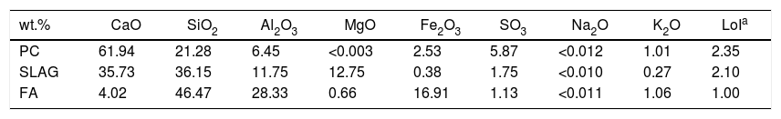
The raw material composition was characterized by (XRF). Table 2 shows the chemical composition of each raw material.
Chemical composition of the raw materials (wt.%) by XRF.
| wt.% | CaO | SiO2 | Al2O3 | MgO | Fe2O3 | SO3 | Na2O | K2O | LoIa |
|---|---|---|---|---|---|---|---|---|---|
| PC | 61.94 | 21.28 | 6.45 | <0.003 | 2.53 | 5.87 | <0.012 | 1.01 | 2.35 |
| SLAG | 35.73 | 36.15 | 11.75 | 12.75 | 0.38 | 1.75 | <0.010 | 0.27 | 2.10 |
| FA | 4.02 | 46.47 | 28.33 | 0.66 | 16.91 | 1.13 | <0.011 | 1.06 | 1.00 |
As shown in Table 2, the three systems contain CaO, SiO2 and Al2O3 as the principal oxides in their composition. In the case of the PC, those oxides are present in the clinker phases (C2S, C3S, C3A, etc.). So, after the hydration of the phases, the main hydration product, C-S-H gel is generated. Regarding the supplementary raw materials, after the hydration of their aluminosilicate phases, it is formed their main hydration products: C-A-S-H gel in the case of the slag and N-A-S-H gel if the fly ash is used [30,31].
Loss on ignition (LoI) was also measured in the systems according to the UNE-EN-196:2:2005 standard, applying a temperature of 1000°C. The results are associated with a slight physically absorbed water of the components and with the weathering and/or carbonation that the materials could suffer during extended storage.
Fig. 5(a) shows the cumulative volume of cement, slag and fly ash, as a function of particle diameter. It is important to highlight that an average particle size (D50) smaller provides a high reactivity, because the total surface area is large and consequently, the contact with water is bigger resulting in a good development of the hydration. The grain size of the cement particles is usually within 7–200μm guaranteeing a high reactivity [32]. As can be seen in Fig. 5(a), all the systems obtain particle sizes between 7 and 200μm. Specifically, the average particle sizes (D50) for PC, SLAG and FA are 19.6μm, 12.9μm and 6.5μm, respectively.
 Cumulative volume as a function of the particle diameter of cement, slag and ash used. (b) Differential volume as a function of the particle diameter of cement, slag and ash used. (c) Cumulative volume as a function of the particle diameter of hybrid mixtures. (d) Differential volume as a function of the particle diameter of hybrid mixtures.")
(a) Cumulative volume as a function of the particle diameter of cement, slag and ash used. (b) Differential volume as a function of the particle diameter of cement, slag and ash used. (c) Cumulative volume as a function of the particle diameter of hybrid mixtures. (d) Differential volume as a function of the particle diameter of hybrid mixtures.
Fig. 5(b) shows the differential volumes of the raw materials as a function of particle diameter. It can be observed that FA clearly shows two modes in contrast to PC and slag, whose modes are very close. This may be related to a possible contamination of the raw material (specially of the FA) with a submicron particle size compound.
Also, the cumulative volume (Fig. 5(c)) and differential volume (Fig. 5(d)) as a function of the particle diameter of the hybrid mixtures were studied. As in the previous case, the average particle size of all the mixtures is between 7 and 200μm, which ensures a good reactivity. Specifically, the percentile D50 is 7.7μm for 80 FA/20 PC-3% system, 8μm for 80 FA/20 PC-5%, 14.4μm in the case of 80 SLAG/20 PC-3% mortar and 19.0μm for 80 SLAG/20 PC-5% mortar. Comparing the hybrid systems with a 5% of sodium sulfate with the ones that are composed by a 3%, it can be observed that the particle size increased. This fact could be produced by the addition of sodium sulfate.
The modal distribution is very similar to the results that we obtained when the raw materials were studied separately. However, in this case, the hybrid systems of cement and slag show only one modal distribution, whereas the hybrid FA contains two modes probably associated with a contamination with a submicron particle size compound.
Fig. 6 shows the mineralogical characterization of raw materials. The FTIR spectrum of PC (Fig. 6(a)) shows bands related to calcium silicates (alite and belite) and aluminates (C3A and C4AF). Symmetric (υ1) and asymmetric (υ3) vibrations of the SiO bond that belongs to the SiO4 groups are manifested in the bands which are observed at ca. 874–890cm−1 and 920cm−1, respectively [33]. The silicate tetrahedra (SiOSi) of the alite and belite phase have a symmetric deformation that is identified with the band at ca. 520cm−1[33] and the presence of poorly resolved band in the region of 750–500cm−1 correspond to C4AF phase [34]. The sulfate groups (SO42−) show an asymmetric tension vibration that is identified with the band between 1100 and 1200cm−1 related to the presence of gypsum added to clinker. Finally, the storage of the cement causes the formation of carbonates, which are shown in the intensity band at ca. 1430cm−1 corresponds to the asymmetric streatching vibrations of the CO bonds of the CO32− and with the presence of another absorption bands at ca. 874cm−1 characteristics of the vibration of deformation of OCO bonds out of the plane (υ2) [33,35,36].
 FTIR spectra of PC; (b) XRD pattern of PC; (c) FTIR spectra of blast furnace slag; (d) XRD pattern of blast furnace slag; (e) FTIR spectra of fly ash; (f) XRD pattern of fly ash.")
When the FTIR spectrum of blast furnace slag (SLAG) is analyzed (Fig. 6(c)), the asymmetric stress vibration of the silicate tetrahedra of the SiO bonds in the thick band has been observed in the range of 850–1050cm−1[31]. Furthermore, these silicate tetrahedra produce a deformation vibration associated with the vibration band of 500cm−1[37]. In the case of the AlO4 groups, the AlO bonds cause an asymmetric vibration, located at ca. 720cm−1. As in the PC system, there are also carbonates caused by storage time.
In the case of fly ash (Fig. 6(e)), the intensity and thickness of a band is distinguished at ca. 1100cm−1, which is related to the asymmetric tension vibration from the SiOSi or AlOAl bonds. There is also a presence of quartz and mullite since bands can be observed at ca. 780cm−1 and 550cm−1, respectively [5].
As for the X-ray diffractogram of PC (Fig. 6(b)), the presence of alite phase (JCPDS 31–301) (2θ=32.07°, 34.29° and 41.14°) and belite phase (JCPDS 33-302) (2θ=32.07°, 32.62° and 33°) are confirmed as the majority phases [31]. Other phases are observed to a lesser extent, such as C3A and C4AF (JCPDS 30-226).
Finally, in the blast furnace slag and fly ash diffractograms (Fig. 6(d) and (f), respectively) a halo is observed with a maximum of 2θ=30–32° and 2θ=20–35°, respectively, which indicates that both precursors are semi-crystalline [5]. Nevertheless, fly ash diffractogram presents somewhat higher crystalline since the crystalline phase of quartz (Q, SiO2; PDF-331161) and mullite (M, Al6Si2O13; PDF-150776) appear.
Mechanical propertiesFig. 7 shows the mechanical behavior of the analyzed systems. As it can be observed, there is a clear difference between slag mortars activated with NaOH 4M solution and the ones activated with sodium silicate solution. In the first one, the compressive strength at 28 days was approximately 30MPa, slightly lower than the strength obtained in the PC mortar. However, when a solution that adds an amount of Si (like sodium silicate) was used, the mechanical resistance increases. At the age of 28 days, the compressive strength of these mortars is about 52MPa. This increase is due to the addition of soluble silica when sodium silicate solution was used. Silicon provides greater consistency and compaction to the main reaction product generated (C-A-S-H gel in this case). In this way, the C-A-S-H gel is more compact, cohesive, and richer in silicon, so the polymerization of this gel causes the development of longer chains [38,39]. Therefore, adding an amount of silicon using waterglass increases the mechanical resistance by about 79%, comparing it to the system that used a NaOH 4M solution [6]. Furthermore, comparing this behavior with the PC system, the compressive strength is also 26% higher.

In hybrid mortars, there is a clear difference between the slag systems and the fly ash ones. Slag systems present higher resistance than the fly ash systems. Slag, in contrast to fly ash, starts to dissolve and generates the main reaction product (C-A-S-H gel) at room temperature. After 28 days of curing, the hybrid systems composed of slag present a slightly lower compressive strength than the one obtained in the PC mortar. This is due to the portion of PC in the hybrid (less than 20%), so the C-S-H gel generated will be much lower than the one present in the reference system. The consistency of the main reaction products generated in the hybrid composed of slag (mixture of gels: C-S-H and C-A-S-H gel) is lower than the C-A-S-H gel generated in the SLAG WG mortar because silicon is not added.
Fly ash hybrid systems show the worst mechanical resistance because fly ash needs a higher temperature to dissolve and to precipitate N-A-S-H gel, which is the main activation product. The heat released by the hydration of the 20% of cement is not enough to favor the formation of the N-A-S-H gel, and consequently the mechanical properties were affected. Also, like occurs in the case before, compressive strength is affected by the small percentage of PC employed (less than 20%). The main reaction products (in these mortars, N-A-S-H gel and C-S-H gel) are not as cohesive as the C-S-H gel produced in the PC mortar.
In addition, both types of hybrid systems are affected because the use of supplementary materials in a high content has a negative impact on the development of early mechanical strength due to the slow reactivity at the beginning [13].
Regarding the solid alkaline activator (Na2SO4), it can be observed that those with 5% of sodium sulfate have higher strengths than the ones with a 3%, regardless of the type of waste they contain. This is because sodium sulfate facilitates the formation of the gels and, consequently, provides a greater consistency. Therefore, attending to the aspects described above, the 80SLAG/20PC-5% mortar is the hybrid mortar with the highest mechanical resistance at the age of 28 days.
In summary, the results in Fig. 7 show that the alkali-activated slag mortar, system using sodium silicate, obtains the best mechanical properties in the compressive test. It registers compressive strengths higher than 52MPa after 28 days of curing.
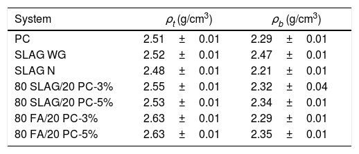
Density, porosimetry and thermal conductivityThe results of theoretical density (ρt) and bulk density (ρb) of the base materials are shown in Table 3. As can be seen, the theoretical densities of all the mortars are very similar. Their values are between 2.49 and 2.64g/cm3. However, a greater variability in bulk density is observed. This indicates that the mortars have different porosity. Porosity determines the mechanical properties because pores are likely areas to produce defects since they act as stress concentrators through which cracks tend to nucleate [40]. Pores create areas of weakness in the solid matrix. In relation to this aspect, Fig. 8 compares the results of total porosity with the compressive strengths obtained in the mortars cured for 28 days. In general, as the total porosity increases, the compressive strength is lower, in accordance with the reason explained earlier. When the reference mortar (PC mortar) is analyzed, it can be observed that it has a total porosity of about 9% at 28 days, a value which is in accordance with the results found in the literature [8].
Theoretical (ρt) and bulk (ρb) densities.
| System | ρt (g/cm3) | ρb (g/cm3) |
|---|---|---|
| PC | 2.51±0.01 | 2.29±0.01 |
| SLAG WG | 2.52±0.01 | 2.47±0.01 |
| SLAG N | 2.48±0.01 | 2.21±0.01 |
| 80 SLAG/20 PC-3% | 2.55±0.01 | 2.32±0.04 |
| 80 SLAG/20 PC-5% | 2.53±0.01 | 2.34±0.01 |
| 80 FA/20 PC-3% | 2.63±0.01 | 2.29±0.01 |
| 80 FA/20 PC-5% | 2.63±0.01 | 2.35±0.01 |

The mortars with the lowest total porosity are the alkali-activated SLAG WG mortars, which have a value around 2%. These results are related to the good mechanical resistance values explained in the previous point, where compressive strengths greater than 50MPa were achieved. This is mainly due to the formation of the C-A-S-H gel, which in this case is very cohesive and compact due to the addition of silicon.
On the other hand, the system with the highest porosity is the 80 FA/20 PC-3%. If it is compared to the reference PC mortar, its porosity is about 47% higher, which coincides with the worst mechanical resistance obtained. Regarding the hybrids manufactured with slag, it can be observed that the porosity values are very close to the one obtained in the reference system. This aspect is also reflected in the compressive strength behavior, since the necessary force to cause the compression failure of the systems is comparable.
Porosity also affects thermal conductivity because air cavities hinder phonon propagation through the material, which influences the heat transfer. Moreover, the conductivity of dry air at room temperature has a value of 0.026W/mK, which reduces the thermal conductivity of the solid material [27,28]. In addition, other characteristics affect the thermal conductivity, such as for example the crystalline structure of the material or the coexistence of different phases, since the interphases and grain boundaries also hinder the phonon propagation.
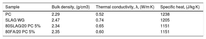
Considering this relationship between porosity and thermal conductivity, Fig. 8 compares the thermal conductivity values with the porosity of the 28-day mortars. The first aspect to highlight is that PC mortars have the lowest thermal conductivity with a value of 0.52W/mK, so the alternatives increase their thermal conductivities regarding the reference (see Table 4). Specifically, it can be observed that SLAW WG and 80SLAG/20 PC-5% mortars are those with the highest values of thermal conductivity. Their values are 42% and 25% higher than the one of the PC, respectively. It is noteworthy that these results are in agreement with the lowest porosity values measured at 28 days. On the other hand, the mortars which contain higher porosity, 80FA/20 PC-3% and SLAG N, have the lowest thermal conductivity values. Despite this fact, their thermal conductivity values are comparable with the PC one. The 80SLAG/20 PC-3% and 80FA/20 PC-5% mortars have similar thermal conductivities.
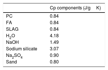
ANSYS Fluent simulationTo see how thermal properties affect the charging of a block composed of these materials, as stated above, the simulation was carried out for four different mortar compositions (the ones with the highest values of thermal conductivity). The simulation includes the different values of bulk density and thermal conductivity, experimentally measured, and the specific heat, which is calculated with the following equation [41–43].
where cp(mortar)=specific heat of mortar; cx=specific heat of material x; and fx=is the weight fraction of each component.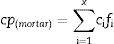
Specific heat values of the different materials used in the mortars can be observed in Table 5[44,45].
It should be noted that the value of water in Table 5 corresponds to the free water in the mortar. The amount of free water in mortar decreases while the reaction products take place. Finally, resulting in a specific heat value of bounded water for hydration as a gel product of 2.2J/gK [42,46,47]. The specific heat values of the mortars shown in Table 4 were calculated with the values defined in Table 5.
Table 4 shows the systems that were chosen to study the heat transfer within the blocks and their properties needed to run the simulation in ANSYS. For each type of system, the mortar with the highest compressive strength and thermal conductivity values was chosen. So, for the alkali-activated mortars, the SLAG WG was selected. SLAG WG obtained higher values than the SLAG N. In the case of the hybrid systems, those with a 5% of sodium sulfate were chosen. PC, the reference sample, also was studied to compare the system with its alternatives.
Before launching the simulation for each mortar, some computational parameters must be selected: number of time steps, that is the number of temporal steps defined in the simulations. These parameters were chosen after the mesh sensibility had been studied. Therefore, the number of time steps was fixed at 3000 for all simulations. This value allows us to see how the heat transfer was carried out for each mortar. This is an appropriate and sufficient value of time to compare the different systems as Fig. 9 shows. The number of iterations for each time step, fixed at 5 for all cases and the size of time steps, which is the time in seconds for each time step, equal to 1s for all simulations.
 Evolution of the temperature in the control point for all the mortars during 3000s. (b) Detail of (a) in the area of interest for our study. (c) Temperature derivate with respect to time (dT/dt). (d) Detail of (c) in the area of interest for our study.")
To analyze the transient thermal conductivity within each block, a control point was selected at the center of the geometry (0.015, 0.015) to monitor the temperature variation with time. Fig. 10 shows the node selected for all mortars.
.")
As it is described in Section “Computational Fluid Dynamic software (CFD, ANSYS Fluent) for thermal energy storage in CSP”, the CSP technology needs a HTF, which is usually water/steam, molten salts or air [48] flows through the tubes inside the block, transferring the heat from the fluid to the solid, while the fluid cools down, changing the phase (condensing) or decreasing the temperature (latent or sensible cooling, respectively). During the discharge process, the HTF flows through the tubes, increasing the thermal energy, increasing the fluid temperature and/or promoting the evaporation of the fluid.
In this work, just to compare the four systems and to analyze the rate of heat transfer inside the blocks, only the charge process was studied. For this aim, it was stablished an initial temperature in the pipe (Fig. 4) of 600K, because it is a value that is within the normal operating temperature range of a concrete used for thermal energy storage [49], and the block was fixed at 300K. This simulation let us observe how is the heat conduction within the mortars. The evolution of the temperature over time in the control point (Fig. 10) for all the mortars is shown in Fig. 9.
At time t=0, the temperature at the control point is 300K (the initial temperature value for the solid block), however, as time goes by, the temperature of the control point increases for all mortars. The time needed to reach 400K in the control point has been reported as a measure of the heat transfer capacity of the block. As can be observed (Fig. 9(a) and (b)), the mortar SLAG WG is the fastest one to reach the 400K, followed by the 80SLAG/20 PC, 80FA/20 PC and finally, the PC. SLAG WG takes about 26% less time than PC to reach 400K. These results agree with those obtained for density, thermal conductivity and specific heat. SLAG WG mortar has the highest values for bulk density (lowest value for porosity) and for thermal conductivity, and one of the lowest values for the specific heat. Therefore, it is worth mentioning that contrary to what could be initially thought, the heat transfer within the block is not only a function of the thermal conductivity, but also a combination of bulk density, thermal conductivity and heat capacity. On the other hand, the PC shows the worst result for thermal conductivity within the block, due to having the lowest bulk density, the lowest thermal conductivity, and the highest specific heat, which implies a higher thermal inertia in the heat transfer processes. Furthermore, focusing on the derivate of the temperature with respect to time (Fig. 9(c) and (d)), the same tendency of the values noted previously can be observed. SLAG WG mortar is the first in increasing its temperature. In addition, it is the one which experiences the highest variation of temperature during the simulation. By contrast, the PC mortar is the last to start changing its temperature and its variation of temperature with time is smaller than the other systems.
ConclusionsThe main purpose of this work was the study of possible alternative materials to Portland cement, specially, of their thermal properties to provide further knowledge of their use as storage media.
The most important conclusions to draw from this study are the following:
- •
The total porosity of the manufactured mortars has an important influence on their compressive strengths and evaluated thermal conductivities. This parameter must be considered for materials that are going to be used as a mean of solar thermal storage. The air present in the pores decreases the thermal conductivity, which is detrimental to this specific application.
- •
The modeling and the calculation parameters used in this work for the simulation with ANSYS Fluent allow an optimal development of said simulation.
- •
The simulated transient heat transfer phenomenon inside the mortars manufactured in this work allow us to describe the behavior of these materials as solar thermal storage solids.
- •
All the alternative mortars studied during the simulation offer greater speed in transmitting the heat inside them than conventional Portland mortars. Specifically, the alkaline-activated mortar with sodium silicate is the one with the best performance as a mean of solar thermal storage.
Therefore, alternative materials for Portland cement obtained after different alkaline activation processes (blast furnace slags) or after manufacture of hybrid systems can be considered for use as solar thermal storage materials. This research opens up a path toward development and application of eco-efficient materials in the energy sector, especially, renewable energies.
This work has been supported by the Madrid Government (Comunidad de Madrid) under the Multiannual Agreement with UC3M in the line of “Fostering Young Doctors Research” (HORATSO-CM-UC3M) in the context of the V PRICIT (Regional Programme of Research and Technological Innovation). Furthermore, the authors of this work would like to thank Noelia Casiano for her help during the tests carried out in the laboratory.

