


Preoperative planning constitutes a fundamental tool in the management of fractures; however, its practical application is far from the desired, perhaps due to the absence of a basic and simple method, adapted to the current times. We describe a digital planning method, halfway the traditional and the technological, which preserves its educational essence, allows for the understanding of the fracture and the individualisation of the osteosynthesis.
Material and methodsAfter the initial analysis of the fracture and the patient's characteristics, different measurements are made on X-ray and CT images with a digital medical imaging software. These images are then copied into a presentation programme (Microsoft® PowerPoint or Keynote ©Apple Inc.), in which the main fragments and fracture lines are traced with the computer pointer. These are subsequently moved into a reduced position and the implants for internal fixation are graphically represented together with a guide of the surgical strategy.
ResultsWe show 4 cases of different types of fractures operated through reduction and osteosynthesis after preoperative planning according to the described method. The basic points for the surgical planning, logistics, tactics and postoperative radiological results of each case are detailed.
ConclusionsDespite the rise of advanced planning software, traditional paper and pencil methods are still fundamental, even more so for the trauma surgeon in training. The digital planning method described is very appropriate for this purpose, as it combines the advantages of both methods: simplicity, accessibility, quickness, low cost, reproducibility, educational character, efficiency and possibility of simulation, corrections and reuse of cases.
La planificación preoperatoria constituye una herramienta fundamental en el manejo de fracturas; sin embargo, su aplicación práctica dista de lo deseado, quizá debido a la ausencia de un método básico y sencillo, adaptado a los tiempos actuales. Describimos un método de planificación digital, entre lo tradicional y lo tecnológico, que conserva su esencia educativa, permite comprender la fractura e individualizar la osteosíntesis.
Material y métodosTras el análisis inicial de la fractura y características del paciente, se realizan diferentes mediciones en las imágenes de Rx y TC con un software de imagen médica digital. Estas imágenes se copian en un programa de presentación (Microsoft® PowerPoint o Keynote ©Apple Inc.), en el que se reproducen con el puntero del ordenador los principales fragmentos y líneas de fractura. A continuación, estos se mueven a una posición reducida y se representan gráficamente los implantes para la fijación interna junto con un guion de la estrategia quirúrgica.
ResultadosMostramos 4 casos de diferentes tipos de fracturas intervenidas mediante reducción y osteosíntesis tras una planificación preoperatoria según el método descrito. Se detallan los puntos básicos para la planificación quirúrgica, logística, táctica y resultados radiológicos postoperatorios de cada caso.
ConclusionesA pesar del auge de programas informáticos avanzados de planificación, los métodos tradicionales con lápiz y papel siguen siendo fundamentales, más aún para el traumatólogo en formación. El método de planificación digital descrito resulta muy adecuado para este objetivo al aunar las ventajas de ambos métodos: sencillez, accesibilidad, rapidez, bajo coste, reproducibilidad, carácter formativo, eficaz y posibilitar la simulación, correcciones y reutilización de casos.
The phrase planning is the key to success has been repeated throughout history with nuances and variants and can be applied to many situations. In Orthopedic Surgery and Traumatology (ORT), emphasis is placed on planning through the use of a proverb with a similar background: Failing to plan is planning to fail, of anonymous origin, being a fact that no surgeon enters the operating room planning to fail, however, it is common to fail to plan.1 Thorough preparation prior to surgery is fundamental to achieve the best results for patients and must not be neglected.
Preoperative fracture planning provides numerous benefits for surgeons and patients. Effective planning reduces the risks associated with inadequate fracture assessment by forcing the surgeon to study fracture tracings in detail, identify anatomical and technical details of the procedure, and define the best way to reduce and fix the fracture based on fracture pattern.2 It also improves surgical efficiency and outcomes1 by allowing surgery to proceed more smoothly, avoiding unnecessarily prolonging surgical time and minimising complications.
For specialists in training, it is a tool to enable management of the fracture prior to the surgical procedure and it provides essential time to understand the fracture pattern and its complexity, and to study the most appropriate approach, reduction technique, and method of osteosynthesis. This will help them approach surgery with greater confidence, guaranteed success, and less stress.1 Despite its importance and the fact that it is one of the elementary subjects and one of those most emphasized in introductory osteosynthesis training courses, its practical application in the day-to-day treatment of fractures is far from what is desired3 although it is widely used in orthopaedic surgery to correct deformities or in prosthetic surgery.4
Traditionally tracing paper, onion paper, or simple measurements on plain radiographic (X-ray), or computed tomography (CT) images have been used for preoperative planning in the treatment of fractures.1,2 These are simple, familiar, low cost, low radiation exposure and educational methods. With the advances in digital medicine, semi-automated planning software and 3-dimensional (3D) printing technology have emerged as promising tools for preoperative fracture planning,5–11 although their use is not as widespread as might be imagined. The disadvantages of new technologies, despite providing precision and simulating fracture reduction and placement of internal fixation implants, are that they are less accessible, more expensive, time-consuming, and complex.
The aim of this paper is to explain in detail a method of surgical planning of fractures that takes an intermediate approach between the traditional and technological methods, which is simple, reproducible, low cost, accessible, relatively fast, and effective. These characteristics and because the method follows the traditional principles of fracture planning, makes it possible to understand the complexity of a fracture and design an individualised therapeutic plan that optimises outcomes for the patient. It is, therefore, very suitable, and instructive for ORT specialists in training, although its use could clearly be extended to more experienced surgeons.
Material and methodsWe present a simple method of preoperative planning that uses widely used commercial presentation software based on X-ray imaging and CT support.
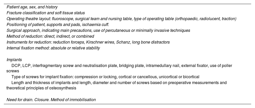
Preoperative assessment and surgical strategyFirst the fracture and patient characteristics are analysed, logistical details such as theatre layout, type of table, patient positioning on the operating table are noted, and the surgical strategy of approach, reduction, fixation, and implants is decided (Table 1).
Preoperative assessment and development of surgical strategy.
| Patient age, sex, and history |
| Fracture classification and soft tissue status |
| Operating theatre layout: fluoroscope, surgical team and nursing table, type of operating table (orthopaedic, radiolucent, traction) |
| Positioning of patient, supports and pads, ischaemia cuff. |
| Surgical approach, indicating main precautions, use of percutaneous or minimally invasive techniques |
| Method of reduction: direct, indirect, or combined |
| Instruments for reduction: reduction forceps, Kirschner wires, Schanz, long bone distractors |
| Internal fixation method: absolute or relative stability |
| Implants |
| DCP, LCP, interfragmentary screw and neutralisation plate, bridging plate, intramedullary nail, external fixator, use of poller screws |
| Type of screws for implant fixation: compression or locking, cortical or cancellous, unicortical or bicortical |
| Length and thickness of implants and length, diameter and number of screws based on preoperative measurements and theoretical principles of osteosynthesis |
| Need for drain. Closure. Method of immobilisation |
DCP: Dynamic Compression Plate; LCP: Locking Compression Plate.
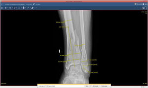
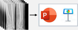
Then, based on the X-ray and multiplanar CT images obtained from the Picture Archiving and Communication System (PACS), different measurements are taken in 2 orthogonal projections with a digital medical image viewer (e.g., XERO Universal Viewer, Agfa HealthCare, Agfa-Gevaert Group, Mortsel, Belgium). The measurements serve as a reference to calibrate subsequent additional measurements and vary according to fracture site, pattern, and method of synthesis (width of tibial plateau or plafond, anteroposterior diameter of the distal femur or tibia, distance from the articular surface to the fracture, width of the medullary canal, etc.). When measurements are made from CT images, the accuracy of these measurements is highly reliable, whereas, for X-ray images, ideally a preoperative marker should be used to calibrate the image or to estimate a magnification of 15–20%.12–14 The X-ray images are exported in jpg/jpeg file format (Joint Photographic Experts Group) and then copied into a presentation programme, Microsoft® PowerPoint 2020 (version 16.44-20121301; Microsoft Office package developed by Microsoft Corporation, Redmond, WA, USA) or Keynote (version 10.3.5-7029.5.5; iWork productivity suite for Mac, 2003–2020 Apple Inc., Cupertino, CA, USA).
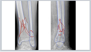
Fracture segmentationThe digital X-ray images are inserted into a new blank slide of any of the above-mentioned presentation programmes and fracture segmentation is performed manually. To do this, select from the toolbar: Insert>Shape>Freeform in PowerPoint or Shape>Draw with the pen tool in Keynote (Fig. 1A, B), and trace the borders of the main fracture fragments and fracture lines freehand with the computer pointer. We recommend choosing a border colour for the fragments (e.g., blue) and another (e.g., red) to highlight the fracture lines (Fig. 1C), which can be distinguished from the black and white of the X-ray images: Shape Format>Shape Outline > Colour in PowerPoint or Format>Style>Border>Line>Colour in the right sidebar in Keynote. In complex fractures, multiplanar CT images with three-dimensional reconstructions provide more preoperative information and better fracture characterisation.
 Tool for drawing shapes “Freeform” in Microsoft PowerPoint. (B) Tool for drawing with the pen tool in Apple Keynote. (C) Tracing the edges of the main fragments (blue) and fracture lines (red). (D) Simulation of reduction of the fracture fragments that are filled with red by setting an opacity of 40%.")
(A) Tool for drawing shapes “Freeform” in Microsoft PowerPoint. (B) Tool for drawing with the pen tool in Apple Keynote. (C) Tracing the edges of the main fragments (blue) and fracture lines (red). (D) Simulation of reduction of the fracture fragments that are filled with red by setting an opacity of 40%.
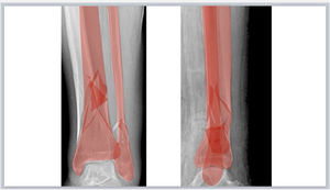
The fragments are then filled with colour (e.g., red) and an opacity of 40% is set to allow transparent visualisation of the bone on the X-ray using the options: Shape Format > Shape Fill > More Fill Colours > Opacity in PowerPoint or Format > Style > Fill Colour > Opacity in the right sidebar in Keynote (Fig. 1.D). The fracture fragments are moved by left clicking on them and dragging or rotating them into a reduced anatomical position. To do this, the principles of reduction must be applied depending on the type of fracture. Thus, in articular fractures we will avoid steps on the articular surface and in diaphyseal fractures we will try to restore the appropriate length and a good coronal and sagittal alignment. In very comminuted fractures where the anatomy is completely unstructured or in diaphyseal fractures, it might be useful to use the intact contralateral limb to trace its contours and guide the reduction.
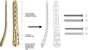
Implant selectionThe principles of osteosynthesis and the surgeon's own experience, the approach, the method of reduction and internal fixation and the appropriate implants are selected based on initial analysis of the fracture. Once the implant has been selected, using the surgical technique manual provided by the company, the image of the implant is copied onto another blank slide to then draw its silhouette and details with the abovementioned freehand or pen drawing tools (Fig. 2A). The screws that will be used to fix the implant to the bone are also drawn using this technique, the length of the implant, the number of screws required, and their size are calculated from the preoperative measurements.
 Drawing of implant silhouette on surgical technique image obtained (medial distal tibial LCP plate, DePuy Synthes®, Johnson & Johnson) and cortical and locking screws with the pen tool in Apple Keynote. (B) Diagram of surgical steps and graphic representation of the reduced fracture and overlapping of the implants fixed with screws, noting the types, sizes, and lengths according to preoperative measurements. KW: K-wires; LCP: locking compression plate; MIPO: minimal invasive plate osteosynthesis.")
(A) Drawing of implant silhouette on surgical technique image obtained (medial distal tibial LCP plate, DePuy Synthes®, Johnson & Johnson) and cortical and locking screws with the pen tool in Apple Keynote. (B) Diagram of surgical steps and graphic representation of the reduced fracture and overlapping of the implants fixed with screws, noting the types, sizes, and lengths according to preoperative measurements. KW: K-wires; LCP: locking compression plate; MIPO: minimal invasive plate osteosynthesis.
Since the planning page in the presentation programme is not real size, to adapt the size of the implants drawn to the scale of the image, a mathematical rule of 3 is made with the previous measurements, and the real measurements of the implants are noted in the drawing and planning scheme. For example, in case 1, the distance from the articular surface to the end of the fracture is 98mm on the sagittal slice of the CT scan, and for the synthesis a plate of 133mm is chosen (to be able to place 3 locking screws distal to the fracture trace), therefore, to calculate the length of the drawn plate the same distance is measured again on the planning sheet (from the articular surface to the end of the fracture), which gives a length of 18.3cm and the size of the plate is calculated in the planning: if the real size of 98mm is 18.3cm on the drawing; 133mm of the real-size plate is 24.8cm on the drawn plate.
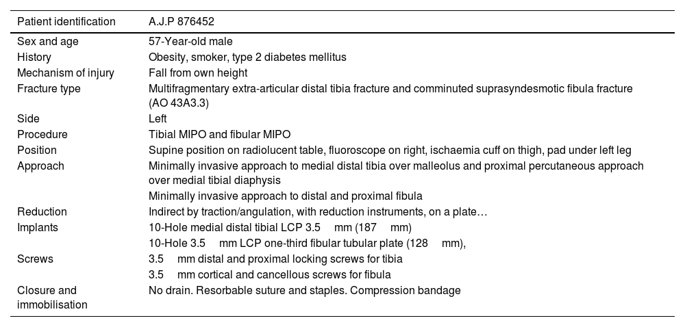
Simulation of internal fixationAfter this, the graphic drawings of the selected implants are superimposed on the X-rays with the reduced fracture representation as a template, simulating the optimal site where they should be placed, and the screws with which they will be fixed are positioned. It is useful to use colours to differentiate each implant and to know the order of placement of each implant for optimal osteosynthesis, together with an orderly written outline of the tactics and logistics of the procedure (Table 2). It is also helpful to include text boxes on the drawing to specify the characteristics and size of each implant.
Example of the written script of surgical tactics and logistics.
| Patient identification | A.J.P 876452 |
|---|---|
| Sex and age | 57-Year-old male |
| History | Obesity, smoker, type 2 diabetes mellitus |
| Mechanism of injury | Fall from own height |
| Fracture type | Multifragmentary extra-articular distal tibia fracture and comminuted suprasyndesmotic fibula fracture (AO 43A3.3) |
| Side | Left |
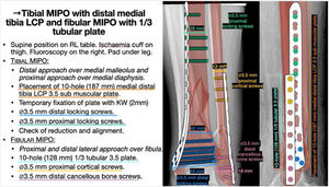
| Procedure | Tibial MIPO and fibular MIPO |
| Position | Supine position on radiolucent table, fluoroscope on right, ischaemia cuff on thigh, pad under left leg |
| Approach | Minimally invasive approach to medial distal tibia over malleolus and proximal percutaneous approach over medial tibial diaphysis |
| Minimally invasive approach to distal and proximal fibula | |
| Reduction | Indirect by traction/angulation, with reduction instruments, on a plate… |
| Implants | 10-Hole medial distal tibial LCP 3.5mm (187mm) |
| 10-Hole 3.5mm LCP one-third fibular tubular plate (128mm), | |
| Screws | 3.5mm distal and proximal locking screws for tibia |
| 3.5mm cortical and cancellous screws for fibula | |
| Closure and immobilisation | No drain. Resorbable suture and staples. Compression bandage |
LCP: Locking Compression Plate; MIPO: Minimal Invasive Plate Osteosynthesis.
The preoperative planning with the written script and technical drawing is printed out and placed in a visible location in the operating room to be used as a guide and consulted by any member of the team. It can also be converted into a portable document format (pdf) to share with the rest of the surgical team prior to the intervention: File>Save as>PDF in PowerPoint or File>Export to>PDF in Keynote. The approach, reduction and internal fixation of the fracture are performed according to the planning, verifying the measurements of the selected implants and screws intraoperatively by direct vision, hand-held surgical metre, and fluoroscopic guidance. It is important to bear in mind that the planning should serve as a guide, but may differ in some respects from the final procedure due to intraoperative findings.
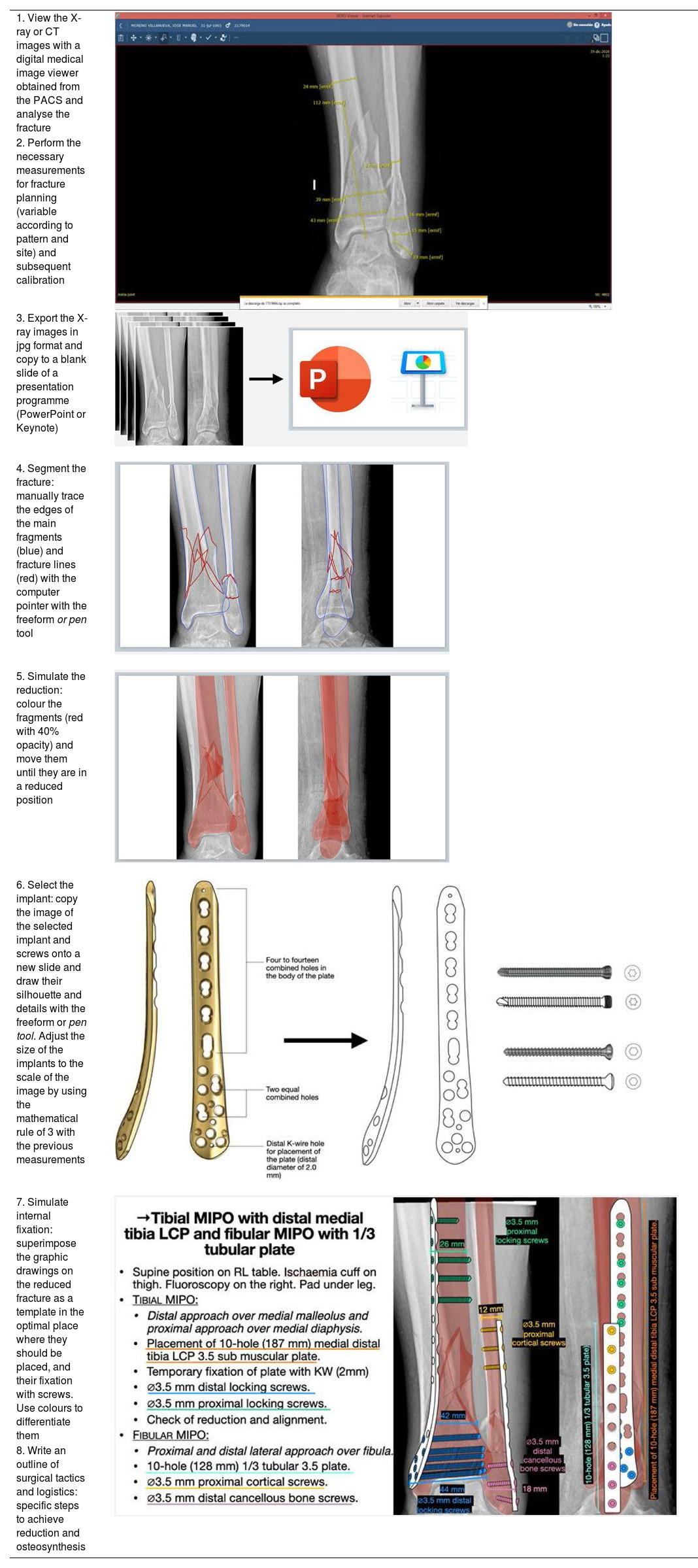
Table 3 shows a summary of the detailed steps for digital planning following the method described.
Summary of steps for digital planning following the method described.
| 1. View the X-ray or CT images with a digital medical image viewer obtained from the PACS and analyse the fracture | |
| 2. Perform the necessary measurements for fracture planning (variable according to pattern and site) and subsequent calibration | |
| 3. Export the X-ray images in jpg format and copy to a blank slide of a presentation programme (PowerPoint or Keynote) | |
| 4. Segment the fracture: manually trace the edges of the main fragments (blue) and fracture lines (red) with the computer pointer with the freeform or pen tool | |
| 5. Simulate the reduction: colour the fragments (red with 40% opacity) and move them until they are in a reduced position | |
| 6. Select the implant: copy the image of the selected implant and screws onto a new slide and draw their silhouette and details with the freeform or pen tool. Adjust the size of the implants to the scale of the image by using the mathematical rule of 3 with the previous measurements | |
| 7. Simulate internal fixation: superimpose the graphic drawings on the reduced fracture as a template in the optimal place where they should be placed, and their fixation with screws. Use colours to differentiate them | |
| 8. Write an outline of surgical tactics and logistics: specific steps to achieve reduction and osteosynthesis |
CT: Computerised Tomography; PACS: Picture Archiving and Communication System; X-ray: plain X-ray.
We show 4 cases as examples of different types of fractures undergoing reduction and osteosynthesis after preoperative planning according to the method described. The sizes and lengths of the implants and screws were determined from measurements on X-ray or CT images and the principles of osteosynthesis.
Case 1. Representative case of planning in tibial plateau fractureA 34-year-old woman presented with a lateral tibial plateau fracture with subsidence and comminution following a skiing accident. The fracture was classified as an AO type 41B215 and Schatzker type III,16 and was scheduled for open reduction with articular surface lift, fill with cancellous bone allograft and internal fixation with cannulated subchondral compression screws and lateral proximal tibial locking compression plate to restore the articular surface and achieve absolute stability (Fig. 3). The lateromedial diameter of the tibial plateau and diaphysis were measured to select the screw size. In addition, the length of the plate was calculated so that 3 locking screws could be placed distal to the fracture trace. As the fracture trace extended distally, a long plate was chosen and, due to the higher workload of this plate, it was planned to place more screws distally for greater stability.
 X-ray and CT images with measurements. (B) Patient characteristics, analysis and segmentation of the fracture and surgical strategy. (C) Surgical tactic list and graphic representation of the planning of open reduction, bone grafting and internal fixation with compression screws and lateral proximal tibial LCP. (D) Postoperative radiological findings. KW: Kirschner wires; LCP: locking compression plate; ORIF: Open reduction and internal fixation.")
Preoperative planning of lateral tibial plateau fracture. (A) X-ray and CT images with measurements. (B) Patient characteristics, analysis and segmentation of the fracture and surgical strategy. (C) Surgical tactic list and graphic representation of the planning of open reduction, bone grafting and internal fixation with compression screws and lateral proximal tibial LCP. (D) Postoperative radiological findings. KW: Kirschner wires; LCP: locking compression plate; ORIF: Open reduction and internal fixation.
An 87-year-old male, independent for basic activities of daily living and active, presented a pertrochanteric fracture AO type 31A1.3.15 This was a fracture with a simple pertrochanteric trace, with the lateral cortex intact and a third fragment involving the lesser trochanter in which an indirect reduction on a traction table and percutaneous reamed cephalomedullary nailing was considered as a method of relative stabilisation and fixation with a distal locking screw in a dynamic position (Fig. 4). Both the choice of the cervico-diaphyseal angle of the nail and the length of the cephalic screw can be determined by using the value of the healthy hip previously measured on the digital medical image viewer on the anteroposterior pelvic radiograph. Alternatively, an angle protractor template can be created following the same technique as described above. In addition, the diameter of the medullary canal at the narrowest area will be measured to calculate the diameter of the nail and the width of the femur to calculate the length of the locking screw. A short nail could be chosen since this was a fracture without mechanical criteria for instability.
 X-ray images with measurements. (B) Patient characteristics, analysis and segmentation of the fracture and surgical strategy. (C) List of surgical steps and graphic representation of planning of closed reduction and percutaneous anterograde cephalomedullary nailing with dynamic distal locking screw. Alternative for measurement of the left cervico-diaphyseal angle using an angle protractor template. (D) Postoperative radiological findings. CR: closed reduction; DL: dyslipidaemia; ER: external rotation; HT: hypertension; IR: internal rotation.")
Preoperative planning of a pertrochanteric femoral fracture. (A) X-ray images with measurements. (B) Patient characteristics, analysis and segmentation of the fracture and surgical strategy. (C) List of surgical steps and graphic representation of planning of closed reduction and percutaneous anterograde cephalomedullary nailing with dynamic distal locking screw. Alternative for measurement of the left cervico-diaphyseal angle using an angle protractor template. (D) Postoperative radiological findings. CR: closed reduction; DL: dyslipidaemia; ER: external rotation; HT: hypertension; IR: internal rotation.
A 57-year-old female, after a fall while practicing sport sustained a diaphyseal fracture of the distal third of the left tibia AO type 42B2c,15 with a multifragmentary suprasyndesmotic fracture of the fibula. The treatment strategy was to perform an indirect reduction of the tibia and internal fixation using an anterograde endomedullary suprapatellar tibial nail (optional), reamed and locked with 3 distal screws to achieve greater stability as the fracture was very distal, and 2 proximal screws, one in a dynamic position to allow dynamization during follow-up if consolidation problems occurred. In these cases, to estimate the appropriate length and diameter of the nail, it is useful to use an X-ray of the contralateral limb, in which the length of the bone and the diameter of the medullary canal at its narrowest area are measured. Likewise, the anteroposterior and mediolateral diameters are calculated distally and proximally in the different directions allowed by the nail to calculate the screw lengths.
On analysis of the fracture, we saw how, being very distal and occurring in the metaphyseal transition zone, there was the possibility of the distal fragment deviating in varus during nailing, and therefore we were able to anticipate and plan where to place a poller screw which, in this case, was in the medial distal metaphyseal zone. Given that the fibula fracture affected the distal 7cm and was comminuted, after restoring the length and alignment of the tibia, an open reduction and internal fixation of the fibula with a one-third neutralization tubular plate was planned to achieve absolute stability, since it affected the ankle joint (Fig. 5), although fixation of the fibula with a plate in this type of fracture is controversial. In this specific case, although an absolute stability technique was considered in the planning, intraoperatively the fracture was very comminuted, and therefore we decided to use plate fixation as a bridge, and relative stability was adopted. Although nailing a fracture appears to be a simple technical procedure, the surgical technique involves many stages, and the planning should not ignore any of them in order to make it an easy procedure to perform.
 X-ray and CT images with measurements. (B) Patient and fracture characteristics, use of contralateral limb as a template to calculate implant length and diameter, and surgical strategy. (C) Surgical tactic list and graphic representation of the planning of closed reduction and endomedullary nailing of suprapatellar tibia (optional) and open reduction and internal fixation internal fixation with one-third tubular neutralisation plate and fibular screws (controversial). (D) Postoperative radiological findings, showing how the fixation of the fibula differs from the planning as a plate was used as a bridge to provide relative stability. CR: closed reduction; IM: intramedullary; KW: Kirschner wire; ORIF: open reduction and internal fixation.")
Preoperative planning of distal tibial diaphyseal fracture. (A) X-ray and CT images with measurements. (B) Patient and fracture characteristics, use of contralateral limb as a template to calculate implant length and diameter, and surgical strategy. (C) Surgical tactic list and graphic representation of the planning of closed reduction and endomedullary nailing of suprapatellar tibia (optional) and open reduction and internal fixation internal fixation with one-third tubular neutralisation plate and fibular screws (controversial). (D) Postoperative radiological findings, showing how the fixation of the fibula differs from the planning as a plate was used as a bridge to provide relative stability. CR: closed reduction; IM: intramedullary; KW: Kirschner wire; ORIF: open reduction and internal fixation.
A 72-year-old female had an accidental fall on a public road, sustaining a periprosthetic fracture of the distal femur around a total knee arthroplasty implanted 11 years earlier. This was a supracondylar femur fracture in which the femoral component of the prosthesis was stable, and was classified as a Lewis and Rorabeck17 type II1 and type V.3-B1 of the Unified Classification System (UCS) classification.18 Since it was a simple diaphyseal fracture, an indirect reduction with a relative stabilisation system, such as a compression bridge plate with locking screws, was considered (Fig. 6). The aim was to restore the length, axis, and rotation of the limb, without requiring a perfect anatomical reduction. The plate would function as an internal fixator without intimate contact with the bone, thus also preserving periosteal circulation. Minimally invasive systems allow the plate and screws to be introduced through minimally invasive approaches and screws to be placed percutaneously. The size of the plate was calculated from the lateral femoral epicondyle and proximally to a distance beyond 2-3 times the fracture length. In case of intramedullary implants or hip arthroplasty stems, the length should be planned with the aim of achieving a minimum overlapping of 30mm, to splint the entire bone and reduce the area of interimplant mechanical stress. Screw size was calculated by measuring the lateromedial diameter of the femur at the distal and diaphyseal levels.
 X-ray images with measurements. (B) Patient characteristics, analysis and segmentation of the fracture and surgical strategy. (C) List of surgical steps and graphic representation of the planning of indirect reduction and internal fixation with LISS-LCP distal femoral plate and percutaneous locking screws. (D) Postoperative radiological result after reduction and fixation with variable angle compression condylar plate and locking screws. CR: closed reduction; DF: distal femur; KW: Kirschner wires; LCP: locking compression plate; LISS: less invasive stabilisation system; MIS: minimal invasive surgery; TKA, Total Knee Arthroplasty.")
Preoperative planning of femoral fracture around a TKR. (A) X-ray images with measurements. (B) Patient characteristics, analysis and segmentation of the fracture and surgical strategy. (C) List of surgical steps and graphic representation of the planning of indirect reduction and internal fixation with LISS-LCP distal femoral plate and percutaneous locking screws. (D) Postoperative radiological result after reduction and fixation with variable angle compression condylar plate and locking screws. CR: closed reduction; DF: distal femur; KW: Kirschner wires; LCP: locking compression plate; LISS: less invasive stabilisation system; MIS: minimal invasive surgery; TKA, Total Knee Arthroplasty.
The cases described here represent a limited number of examples; however, this planning method can be applied to almost any type of fracture and in almost any site, provided we have the appropriate imaging tests for characterisation and calibration. Therefore, in our centre we have applied this digital planning method to fractures of the proximal, diaphyseal and distal humerus, forearm, wrist, pelvis, acetabulum, proximal, diaphyseal and distal femur, proximal, diaphyseal and distal tibia, ankle, and calcaneus, in primary, periprosthetic and peri-implant fractures, and in simple as well as complex fracture patterns.
DiscussionThere are many references in the scientific literature on the importance of good preoperative planning in the surgical treatment of fractures and its benefits have been widely demonstrated. There are now many, varied methods of preoperative planning that are in continuous development. Despite this, there are hardly any texts and scientific publications that explain the planning process in detail, step by step so that it can be applied in practical day-to-day cases.
With advances in osteosynthesis knowledge, transmitted over decades in many training courses, and even in books such as Basic Principles in Fracture Treatment,2 preoperative planning has become valued as a tool in fracture management. These sources constitute some of the most important resources for learning about basic fracture planning following the traditional method, which involves drawing the fracture fragments on tracing or onion paper from the X-ray images and then fitting them together like a puzzle to simulate their reduction. Transparencies of the implants are superimposed as templates, which are traced over the fracture drawing. This method has been applied by other authors, who have highlighted its benefits in helping communication between surgical team, specifying the roles of each member, enabling the preparation of the necessary instruments, reducing the dose of intraoperative fluoroscopy and avoiding unnecessary delays, unforeseen events, and confusion during the operation.1 It also improves technical outcomes by enabling more precise application of theoretical knowledge about the appropriate implant type, optimal placement site and fixation method, among others.19 Comparing the postoperative result with the preoperative planning leads to reflection and improvement of the future planning process.20
Planning methods that employ more sophisticated technology have been greatly developed in recent years. Computer-assisted surgical planning methods have been described for the virtual reproduction of fractures and simulation of fracture reduction and fixation5,8,10 and methods using 3D printing technology, which converts a computer-generated 3D image into a physical model6,9 that aids in preoperative planning and allows implants to be modelled and adapted to individual bone morphology. In general, these methods have great potential, but are currently technically complex, less reproducible, have a long learning curve, are time-consuming, costly, and difficult to access, which has led to their use being less widespread for the time being.21 Furthermore, the clinical benefits11,22,23 and cost-effectiveness of these advanced planning systems24 have not been fully demonstrated.
With technological advances, the manual and attentive process of tracing bone fragments and fracture lines, and the manual simulation of reduction and fixation with implants, is being lost to a large extent.20 To date, we are not aware of any work using commercial presentation programmes that are simple and widely used to facilitate digital planning following the traditional method such as the one we propose and have been using successfully for the last few years. The alternative planning method we describe has more similarities to that proposed by Jamali et al.,25 and by Kim et al.,26 to correct deformity and not for fracture management, which use a photo and image editing software, Adobe® Photoshop® (Systems Inc, San Jose, CA, USA). However, it requires computer knowledge of that software, unlike the abovementioned presentation programmes, which are widely used in our society to communicate ideas or projects in various contexts, from the educational environment such as schools or universities, the scientific environment, to the business and service sector.
One of the great advantages of the abovementioned digital planning method compared to conventional techniques is that it is faster, modifications can be made to it and errors corrected without having to restart the process, and the plans can be saved and reused, and libraries of implants created for future cases. Compared to planning techniques that use more advanced technology, the advantages of the method described are its simplicity, low cost, minimal learning curve, accessibility, and reproducibility. Drawing the anatomy and fracture develops visuospatial and recognition skills, as well as, motor skills in surgical performance.20 In addition, drawing the implants leads the surgeon to become familiar with the implants and to precisely know the lengths and design of each specific plate or nail, and to know the inventory of implants available at their centre and the need to order specific implants or sizes. Another strength of this planning method is that it preserves the instructional character of traditional methods: in the teaching environment it is a simple and indispensable tool for the specialist in training. In this sense, it helps the surgeon to prepare cases thoroughly, encourages the search for for the most appropriate solutions, facilitates the mental rehearsal of the surgical plan, allows solid and lasting learning of the surgical technique, forces the specialist in training to make decisions, stimulates educational discussions between residents and more experienced specialists, and makes the surgical approach more consistent. Therefore, we advocate digital planning following the described method even for relatively simpler fractures in which trainees can be involved, since early introduction to the practice of planning with simple cases will improve their ability to deal with the real case and their experience in planning more complex fractures.
The limitations of this planning technique are those derived from the quality of the diagnostic images and the accuracy of the measurements made on the digital medical image viewer from X-ray or CT scans. Therefore, we recommend intraoperative verification of implant sizes and lengths, which are decisive to ensure correct sizing. Nevertheless, significant deviation from preoperative planning serves as a warning of a of potential surgical error.14 Another obvious limitation is the use of 2-dimensions, as this is a basic method, in contrast to advanced methods, which use 3-dimensions and are more in line with the real anatomy. Despite the limitations, we demonstrate how with universally available commercial presentation software, preoperative planning can be performed easily and efficiently for ORT procedures and are of great educational value.
ConclusionsThe basic method of digital preoperative fracture planning described employs a digital medical image viewer for measurements of X-ray and CT images and the commonly used and widely available presentation programmes for reproducing fracture fragments and fracture lines, as well as simulating the reduction and the graphical representation of implants. This method combines the advantages of the traditional pencil and paper technique, being simple, reproducible, low cost, accessible and relatively fast and efficient, with those of advanced methods, by simulating reduction and fixation with implants, correcting errors without having to restart the process and saving and reusing the plans for future cases. Moreover, since it involves detailed fracture analysis and is based on the basic principles of osteosynthesis, it is of great interest from an educational point of view and is a very suitable tool for ORT specialists in training.
For all these reasons, we encourage trauma surgeons in training to use this method of preoperative planning of the fractures they face on a day-to-day basis to acquire greater experience in its management and to optimise their results.
Level of evidenceLevel of evidence v.
FundingNone of the authors have received payment or other benefits from any commercial entity related to the subject of this article.
Conflict of interestsThe authors have no conflict of interests to declare.
