


Calcaneal fractures can be high energy intra-articular injuries associated with joint depression. Challenges to fracture reduction include lateral wall blow out, medial wall overlap, comminution and central bone loss. Secondary deformity such as hindfoot varus alters foot biomechanics. Minimally invasive approaches with indirect reduction of the calcaneal tuberosity to maintain the reduction using posterior screws is routinely being used in the treatment of joint depression fractures. Biomechanically, optimum screw numbers and configuration is not known. Biomechanical studies have evaluated and proposed different screw configurations, however, it is not clear which configuration best controls varus deformity. This study aims to determine the optimum screw configuration to control varus deformity in Sanders 2B calcaneal fractures.
MethodsSawbone models were prepared to replicate Sanders type 2-B fracture, with central bone loss and comminution. 0.5cm medial wedge of the calcaneal tuberosity was removed to create varus instability. After stabilising posterior facet with a single 4mm partial threaded screw, and applied an 8 hole contoured plate to stabilise the angle of Gissane, inserted one or two 7mm cannulated partially threaded Charlotte™ (Wright Medical Technology, Inc. 5677 Airline Road Arlington, TN) Headless Multi-use Compression (under image guidance) extra screws to control varus and subsidence deformity of the fracture. Coronal plane displacement of the dissociated calcaneal tuberosity fragment relative to the body when applying 5N, 10N and 20N force was measured in millimetres (mm).
Results2 screws inserted (one medial screw into the sustentaculum talus from inferior to superior and, one lateral screw into the long axis anterior process) provides the least displacement (0.88±0.390 at 5N and 1.7±1.251 at 20N) and the most stable construct (p<0.05) when compared to other configurations. A single medial screw into the sustentaculum tali (conf. 3) resulted in the least stable construct and most displacement (4.04±0.971 at 5N and 11.24±7.590 at 20N) (p<0.05).
ConclusionThis study demonstrates the optimal screw configuration to resist varus in calcaneal fractures using minimally invasive techniques. Optimal stability is achieved using 2 screws; one located along the long axis of the calcaneus (varus control) and the other placed in the short axis directed towards the posterior facet of the calcaneus (control varus and subsidence). Further cadaver research would help evaluate optimal screw placement in simulated fractures to further assess reproducibility.
Las fracturas de calcáneo suelen ser lesiones intraarticulares de alta energía asociadas con hundimiento articular. Además, se añade con frecuencia el estallido de la pared lateral, la superposición de la pared medial, la conminución y la pérdida de hueso bajo la carilla articular. La deformidad secundaria, como el varo del retropié, altera la biomecánica del pie. Nuestra comunidad utiliza cada vez más abordajes mínimamente invasivos con reducción indirecta de la tuberosidad del calcáneo para mantener la reducción mediante tornillos posteriores. Hay estudios que proponen diferentes configuraciones de tornillos, tras experimentación biomecánica, pero aún no es bien conocido qué configuración controla mejor la deformidad en varo. Este estudio tiene como objetivo determinar la configuración óptima del tornillo para controlar la deformidad en varo en las fracturas de calcáneo Sanders 2B.
MétodoSe prepararon modelos en Sawbone para replicar la fractura de Sanders tipo 2B, con pérdida de hueso central y con conminución. Se eliminó una cuña medial de 0,5cm de la tuberosidad calcánea para crear inestabilidad en varo. Tras estabilizar el ángulo de Gissane con un tornillo aislado parcialmente roscado de 4mm y una placa moldeada, se utilizaron tornillos de compresión multiuso Charlotte (Wright Medical Technology, Inc. 5677 Airline Road Arlington, TN) sin cabeza, canulados y parcialmente roscados de 7mm insertados sobre una AK bajo escopia. El desplazamiento del plano sagital del fragmento de tuberosidad fracturado en comparación con el cuerpo al aplicar una fuerza de 5N, 10N y 20N se midió en milímetros (mm).
ResultadosDos tornillos insertados (un tornillo medial en el sustenaculum tali de inferior a superior y un tornillo lateral en el eje largo del astrágalo) proporciona el menor desplazamiento (0,88±0,390 a 5N y 1,7±1,251 a 20N) y resulta la construcción más estable (p<0,05) en comparación con otras configuraciones. Un tornillo medial dirigido hacia el sustenaculum tali (conf. 3) dio como resultado la configuración menos estable y el mayor desplazamiento (4,04±0,971 a 5N y 11,24±7,590 a 20N) (p<0,05).
ConclusiónEste estudio demuestra la configuración óptima de los tornillos para resistir el varo en las fracturas de calcáneo utilizando técnicas mínimamente invasivas. Se consigue colocando 2 tornillos; uno de ellos localizado siguiendo el eje largo del calcáneo (control del varo) y otro en el eje corto, dirigido hacia la faceta posterior del calcáneo (control del varo y hundimiento). La investigación adicional en cadáver ayudaría a evaluar la colocación óptima del tornillo en una fractura simulada para mejorar la reproducibilidad.
Calcaneal fractures are the commonest tarsal fractures accounting for 60%.1 75% are intra articular and arise from high energy axial loading injuries.1,2 Anatomical fracture reduction improves function and reduces risk of secondary deformities. Malreduction alters foot biomechanics, increases joint degeneration and results in tendon/joint impingement.3,4
The importance of minimally invasive techniques allow closed reduction, percutaneous fixation and avoids soft tissue trauma that arises from large flaps.3–7 Arthroscopic and sinus tarsi (ST) approaches allow posterior facet reduction and screw fixation into the ST fragment.5–7 The ST approach allows reduction and plate stabilisation at the angle of Gissane.5–7 Restoration of the calcaneal tuberosity axial length and height aids reduction of the lateral and medial walls and decreases varus malalignment. Posterior percutaneous screws are increasingly being used to control and hold the calcaneal tuberosity.8,9
Challenges to reduction and fixation of calcaneus fractures are subchondral bone loss, varus collapse of the calcaneal tuberosity, comminution, lateral wall blow out and medial wall overlap requiring transcalcaneal reduction.8,9 Cadaveric studies have shown similar construct stiffness when loaded to failure, when evaluating percutaneous screw fixation versus perimeter plating showed.8 Optimal posterior screws placement to resist the medial/lateral forces and maintain axial length, alignment and stability to allow early mobilisation recently has been studied by Zhang et al.10 They concluded early weight-bearing induces calcaneus stress fractures and further complications like plantar fasciitis and heel pain, so did not support its use. The aim of this study was to assess the stability of different configurations of posterior screw constructs that best resists varus displacement of the calcaneal tuberosity with respect to the calcaneal body.
MethodsCalcaneal Sawbone® models were available for use for this study. All calcaneal models were standardised to a 5-part depression type fracture configuration with a single fracture line through the posterior facet. This provided identical configurations of bone to allow us to compare fixation models that cadavers would not be able to provide (Table 1).
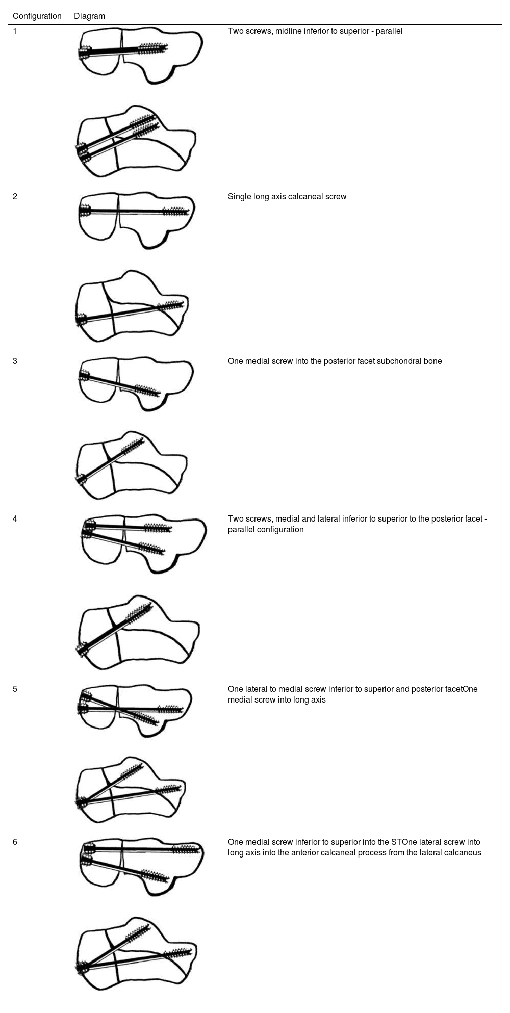
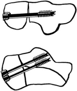
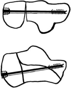
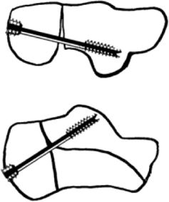
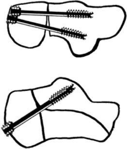
Various configurations of screw placement.
| Configuration | Diagram | |
|---|---|---|
| 1 | Two screws, midline inferior to superior - parallel | |
| 2 | Single long axis calcaneal screw | |
| 3 | One medial screw into the posterior facet subchondral bone | |
| 4 | Two screws, medial and lateral inferior to superior to the posterior facet - parallel configuration | |
| 5 | One lateral to medial screw inferior to superior and posterior facetOne medial screw into long axis | |
| 6 | One medial screw inferior to superior into the STOne lateral screw into long axis into the anterior calcaneal process from the lateral calcaneus | |
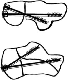
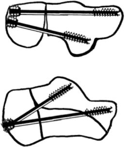
The Sawbone® models replicated a Sanders type 2B fracture joint depression type fracture with secondary fracture line in the anterior process. To remove stability and dissociate the calcaneal tuberosity, a 0.5cm width of Sawbone® was removed from the calcaneus in the form of a medial wedge, illustrated in Fig. 1. The calcaneal tuberosity thus had no continuity with the main body. This was 1cm from the posterior edge of the calcaneus both inferiorly and superiorly. This would simulate varus instability and remove any medial buttress.
 showing the 0.5cm medial wedge of Sawbone®. Bottom – Sawbone® model replicating Sanders 2-B. The subtalar posterior facet was reduced and fixed with a cannulated 4.5mm screw into the ST fragment.6 An 8 hole locking plate was placed on the lateral wall and locked with 3.5mm screws as illustrated in Fig. 2.")
Top – the calcaneal tuberosity was osteotomised to simulate remove varus stability, medial buttress and dissociate the tuberosity with (*) showing the 0.5cm medial wedge of Sawbone®. Bottom – Sawbone® model replicating Sanders 2-B. The subtalar posterior facet was reduced and fixed with a cannulated 4.5mm screw into the ST fragment.6 An 8 hole locking plate was placed on the lateral wall and locked with 3.5mm screws as illustrated in Fig. 2.
Sawbone® was removed using a 3mm burr to simulate subchondral bone loss that would occur in vivo from the depressed lateral fragment. Subchondral saw bone was removed from the lateral posterior facet fragment to within 2mm from the surface thus simulating in vivo bone loss. In vivo, this affects screw purchase.
A single screw partially threaded 4mm cancellous screw was placed into the subtalar fragment originating 1cm below the posterior facet lateral wall, to reduce the posterior facet. A 2mm 8-hole Wright medical plate (Wright Medical Technology, Inc., 5677 Airline Road, Arlington, TN) was contoured and applied to stabilise the crucial angle of Gissane.
Charlotte™ Headless partially threaded 7.0mm screws were used (core diameter 5mm, thread diameter 7mm, 16mm distal thread length) for this study. Partially threaded screws were available and therefore used for this experiment and to standardise screw construct. This is in line with most papers that have used posterior screws to date.11,12 Different screw types of such as fully threaded screws may improve purchase, however, bone loss may negate some of this benefit. Partially threaded vs fully threaded was not assessed in this experiment. Bone stability was mainly achieved from the buttressing affect at the distal tip to support the posterior facet and bone purchase from the distal screw thread near the tip. The differentially pitched thread at the head, purchases the cortical bone in the tuberosity fragment to provide axial length control. Compression that arises from the differential thread pitches is less than 1mm compression, which we felt acceptable. Central bone loss would possibly negate some of the additional purchase from the distal screw thread.
Wires inserted into the tuberosity under fluoroscopy verified optimal screw position (Fig. 2). Manual reduction of the calcaneal tuberosity was maintained to ensure its adequate position in neutral calcaneal alignment when positioning screws. Maintaining calcaneal tuberosity alignment and axial length in the presence of lateral wall comminution, medial wall overlap, and central bone loss can be difficult. In vivo, short flexors and abductors originating from the medial calcaneal tuberosity exert a varus force. This is compounded by the slight medial pull of the tendo-achilles. In vivo, calcaneal tuberosity reduction can be maintained using Hintermann retractors medially (the senior author's preference). In addition, a Steinman pin can be placed into the posterior tuberosity away from the site of screw insertion, or even perpendicular to the calcaneum in the tuberosity fragment to provide temporary traction or axial length control to help reduce varus prior to posterior screw insertion. 2 Charlotte guide wire also helps maintain position during screw insertion under fluoroscopy.
 Single cannulated 4mm screw into sustentacular (ST) fragment. (2) Locking plate (8-hole) on lateral wall with 3.5mm screws. (3) 7.0mm MUC screw (partially threaded 16mm) placed under guide wire technique to achieve <5mm from subchondral bone. (4) Manual reduction for neutral alignment to prevent compression and varus malreduction.")
Image guided fluoroscopy radiography was used to verify construct positions. This radiograph demonstrates: (1) Single cannulated 4mm screw into sustentacular (ST) fragment. (2) Locking plate (8-hole) on lateral wall with 3.5mm screws. (3) 7.0mm MUC screw (partially threaded 16mm) placed under guide wire technique to achieve <5mm from subchondral bone. (4) Manual reduction for neutral alignment to prevent compression and varus malreduction.
Manual distraction in our Sawbone® models ensured a 0.5mm medial gap was maintained during screw insertion. Larger core diameter screws allow a larger distal screw tip surface area to buttress the subchondral bone and minimising cortical penetration. Radiographic verification was used to place screws within 2mm of the subchondral bone surface.
Screws directed to the lateral posterior facet, placed beneath the subchondral bone may act more as a buttress due to limited bone in this area. They were used in a positional fashion to maintain axial length and provide angular stability. The medial side gap of 0.5cm was verified medially prior to the varus force application.
We defined the long axis screw as a screw into the anterior process of the calcaneum. Screws were measured prior to insertion using the cannulated wire system and checked under image guidance to ensure screw position, approximately 2mm from subchondral bone. All posterior facet screws were inserted to within 2mm of the joint surface to support/buttress the subchondral bone. The screw tip acts as a buttress, at the posterior facet.
Six screw configurations were assessed. These included a single screw construct to support the subchondral bone in then posterior facet, a single long axis screw and 2 screw configurations. These included 2 midline central screws, 2 screws to support the subchondral posterior facet and a long axis screw with a single screw to support the subchondral bone (Table 1).
The anterior process of the calcaneus was the held in a rigid clamp applied to the assessment table. Medial displacement of the tuberosity fragment when applying a constant force at 5N, 10N and 20N using a Newton metre [FPX 25 Algometer (Wagner Instruments, Greenwich, USA] was measured using digital Vernier callipers in millimetres (mm). Dual callipers were used to measure both the displacement of the body fragment, and the displacement of the tuberosity fragment when a force was applied as illustrated in Fig. 3. The displacement of the tuberosity with respect to the body could then be attained. A mean of 5 measurements were obtained.

The null hypothesis is that there is no difference in one screw vs 2 screws and the configuration of screw position does not make a difference. The degree of displacement was analysed with Graphpad Prism 7.0 USA using Two-way Anova test with post hoc multiple comparison for a significance level of 0.05 (Table 2).
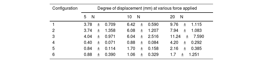
Degree of displacement (mm) at various force applied at different configurations.
| Configuration | Degree of displacement (mm) at various force applied | ||
|---|---|---|---|
| 5N | 10N | 20N | |
| 1 | 3.78±0.709 | 6.42±0.590 | 9.76±1.115 |
| 2 | 3.74±1.358 | 6.08±1.207 | 7.94±1.083 |
| 3 | 4.04±0.971 | 6.04±2.516 | 11.24±7.590 |
| 4 | 0.40±0.071 | 0.88±0.084 | 4.20±0.292 |
| 5 | 0.84±0.114 | 1.70±0.158 | 2.16±0.385 |
| 6 | 0.88±0.390 | 1.06±0.329 | 1.7±1.251 |
Two screws inserted in configuration 6 (one medial screw into the sustentaculum tali and one lateral screw into the long axis) provided the least displacement (0.88±0.390 at 5N and 1.7±1.251 at 20N) and the most stable construct (p<0.0001) when compared to other configurations as illustrated in Fig. 4 and Table 2. So, configuration 6 exhibited increased stability with the least displacement with a statistical difference at various points when 5N (p<0.0001), 10N (p<0.0023) and 20N (p<0.0241) applied. One medial screw into the sustentaculum tali (conf. 3) resulted in the least stable construct and most displacement (4.04±0.971 at 5N and 11.24±7.590 at 20N) (p<0.05) (Table 3).
 at various force applied at different configurations.")
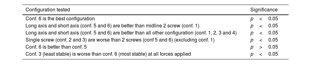
Summary of results. The degree of displacement was analysed with Graphpad Prism 7.0 USA using Two-way Anova test with post hoc multiple comparison for a significance level of 0.05.
| Configuration tested | Significance |
|---|---|
| Conf. 6 is the best configuration | p<0.05 |
| Long axis and short axis (conf. 5 and 6) are better than midline 2 screw (conf. 1) | p<0.05 |
| Long axis and short axis (conf. 5 and 6) are better than all other configuration (conf. 1, 2, 3 and 4) | p<0.05 |
| Single screw (conf. 2 and 3) are worse than 2 screws (conf 5 and 6) (excluding conf. 1) | p<0.05 |
| Conf. 6 is better than conf. 5 | p>0.05 |
| Conf. 3 (least stable) is worse than conf. 6 (most stable) at all forces applied | p<0.05 |
There was no statistical difference between configuration 6 (lateral screw into the long axis and a medial-posterior facet screw), when compared to configuration 5 (medial screw into long axis and post-lateral facet screw) (p>0.05) (Table 3).
When comparing all the single screws (configuration 2 and 3) to 2 screw configurations the results are not significant. However, when comparing the single screw to 2 screws (but excluding configuration 1, 2 midline screws) the results show that 2 screws are better than 1 screw p<0.05 (Table 3).
DiscussionIn this study we evaluate various posterior screw placement configurations in calcaneal fractures to resist varus displacement.1,8 Studies to determine optimum configuration of posterior screw placement have been done, but not exactly in the context of assessing resistance to varus displacement.13 Ivanov showed that a screw that buttressed the posterior facet provided resistance to failure of the posterior facet but did not assess its resistance to varus displacement.14 Finite element modelling work by Zong-Hui showed that 2 crossed screws to fix posterior articular surface from calcaneal tuberosity and 2 parallel screws to fix the calcaneocuboid joint from calcaneal tuberosity dispersed stress the greatest.15
Approaches to calcaneal fractures utilising more minimally invasive/arthroscopically assisted approaches negate the need for large extended flap approaches.5–7 Recent practices and literature reflect this.1,8 Large flaps using the extended lateral approach may increase wound complication/breakdown rates.1,8
Historically fixation techniques have evolved. With the advent of locking Plates,11,12 headless screw14,15 and minimally invasive approaches.16
Prior to anatomical calcaneal plates Carr evaluated the use of semi-third tubular plates and DCP plates in 13 cadaver feet with an impact loading device.17 Using an extensile lateral approach, internal fixation of the posterior facet was undertaken through medial and lateral approaches using 3.5-mm interfragmentary screws. Cadavers were then randomly assigned to either a five-hole 1/3 tubular or five-hole reconstruction plate applied to the lateral cortex. Feet were cyclically compressively loaded at 98N to 500 cycles to assess load to failure. Displacement at the posterior facet at the 500th cycle was 0.30+/−0.08mm and 0.39+/−0.18mm for the tubular and reconstruction plates respectively. This was not significant demonstrating one third semi tubular plates can be used successfully.17 Blake found no significant difference between locking vs non locking plates in osteoporotic Sanders IIB calcaneal fractures in when comparing ten matched pairs of calcaneum cadavers axially loaded to failure over 1000 cycles through the talus.11
Illert also found no statistical difference when axially cyclically loading fresh frozen cadavers with respect to displacement of the posterior facet between locking and non-locking constructs when using 2mm fragment displacement as an endpoint.12
Redfern looked at paired of fresh-frozen cadaver feet, fixed with non-locking or locking calcaneal plates. After cyclically axially loading with a force through the tibia from 0 to 700N at 1Hz no significant difference in cycles to failure was observed.18
However, with the potential of wound healing problems, skin necrosis, infection and potential damage to the peroneal artery, increased adoption of the sinus tarsi approach and percutaneous fixation techniques have evolved. Smerek compared percutaneous posterior 6.5mm partially threaded cancellous headed screw placement with vs perimeter non locking plating for Sanders 2B fractures and found similar force to failure with axial force compression. Both 6.5 screws were placed into the anterior process and did not support the posterior facet and no bone loss was present as osteotomies were created in his model.19
Stupay evaluated the angle subtended when placing longitudinal posterior screws into the anterior calcaneal process. They called it the Tuber-to-Anterior Process Angle (TAPA) angle was 10 degrees lateral to the long axis of the foot. This angle can facilitate the placement of the posterior screw into the calcaneus.20
Wang looked at the use of augmenting fixation with posterior screw placement. They looked at the results of a lateral buttress plate vs plate and longitudinal screws and found in 20 fresh frozen specimens augmenting the lateral column fixation with a single longitudinal screw improved fixation strength from 805N vs 2905N. The screw was placed from superior to inferior in an unconventional manner.6
Weng et al. looked at plate fixation vs minimally invasive percutaneous screw fixation vs sinus tarsi approach and plate fixation with an 8–10-year follow-up and found percutaneous screws had fewer complications but less good quality of fixation compared to the plate fixation group. Percutaneous fixation was in the form of 2 long axis screw. Stability in varus was not assessed. However, despite less good fixation range of motion and were significantly better in the percutaneously reduced group in Sanders 2 fractures.21
Feng did an RCT to evaluate displaced intraarticular fractures. They found that percutaneous screws and calcaneal calcium sulphate graft had fewer complications (7.1% vs 28.9%, p<0.001) than plate fixation and sagittal motion was significantly better in the percutaneous group at final follow-up. They used 2 sinus tarsi screws and 2 posterior long axis screws placed superiorly and inferiorly in the calcaneus. Pure percutaneous screws were not able to control the calcaneal width.22
Kir MC, evaluated the use of percutaneous screws in calcaneal fracture fixation using partially threaded screws vs plate fixation. They found that pate fixation did better clinically. Posterior screws were placed into the anterior process and to the posterior subtalar facet.13
Our construct used a small plate to in situ allow the incision to be kept small. Mini plating and fixation of the ST fragment allows stabilisation at the crucial angle of Gissane and allows the posterior facet to be reduced. Applying a longer plate laterally that extends posteriorly into the calcaneal tuberosity would need a longer incision. The use of posterior screw would negate this and help keep hardware within the bone and decrease injury to the sural nerve and the peroneal artery.
Optimum percutaneous screw placement with respect to prevent calcaneal varus displacement has not been assessed to date. Our results demonstrate midline screws provided the least resistance to varus (configuration 2, 3) despite using 2 midline screws (configuration 1). Single screw constructs provide significantly less resistance to varus instability compared the use of 2 screws (excluding configuration 1) (p<0.05). Varus translation of 5mm or more with single screw construct, and up to 15mm in some scenarios could alter foot biomechanics from resultant varus leading to lateral overload.22 The most stable configurations were 2 screws not used in the midline (configuration 5 and 6). The long axis screw and a subtalar screw provide the most stable configuration. The most stability was attained by a lateral long axis screw and a medial screw into the sustentaculum tali fragment particularly with higher forces (configuration 6), but this was not statistically different compared to other long axis screw construct (configuration 5) (p>0.05). Comparing configuration 3 (least stable) and configuration 6 (most stable), configuration 6 exhibited increase stability with the least displacement at various points when 5N (p<0.0001), 10N (p<0.0023) and 20N (p<0.0241) applied. Orientation of the posterior facet screw from lateral to the medial ST fragment gives the purchase of good bone in the ST region and may be useful if the lateral side is very comminuted negating the opportunity for good subchondral buttress and support.6 The concave medial anatomy of the calcaneus does not allow medial screw position and purchase in the sustentaculum tali fragment with the best unaffected bone. Long axis screws give good bone purchase within the anterior process and therefore, provide resistance to axial and varus displacement deformation. To date this has not been evaluated. Better fixation allows earlier subtalar joint mobilisation without displacement and therefore improves range of motion.8
Calcaneal fracture fixation still follows standard procedures regardless of approach. Joint depression fractures are associated with central bone loss. Posterior facet anatomic reduction in reconstituting the integrity of the subtalar joint is the primary aim. A partially threaded lag screw perpendicular to the fracture line provides compression and holds this reduction and biomechanical studies demonstrate no difference between 3.5-mm cortical screws versus unicortical 4.0-mm cancellous screws.19
Challenges to evaluation of optimal screw placement include variation in screw types, number, size and position including divergent and convergent configurations. The posterior calcaneal surface comprises the gliding surface of the tendoachilles (TA) and the insertional footprint of the TA,23 approximately 100mm2 on our saw bone model. Theoretically although 3 or 4 screws may be used, our calculations show room for 2 good screws.24 60–70% surface area of the posterior calcaneal surface is the insertion of the TA and its gliding surface. Higher insertion of a 3rd screw higher may compromise the posterior gliding surface of the TA. The area for screw insertion inferior to the TA insertion is approximately 3cm2. The 7mm diameter MUC screw head surface area utilised is therefore 38mm2. The additional provision of a 2mm circumferential bone rim with the screw head is approximately 1cm2. 2 screw usage provides a safe footprint. Further screw are compromised by limited surface area of bone available at screw insertion below the insertion of the TA.
The differential benefits of headless vs headed screws is unknown in percutaneous fixation. Both result in compression. On tightening cortical screws, the head abuts the tuberosity cortex, compresses and countersinks into the cancellous bone. In the presence of porotic bone and bone loss significant axial compression can therefore occur. Advantages of threaded heads reside in the heads ability to purchase solid cortical bone and lie flush at the surface thus lacking hardware prominence. Calcaneal axial length loss arising from compression by the differential pitch of this headed screw is 0.9mm25 which we consider negligible in vivo. The fixation advantage of providing a distal buttress for subchondral bone and cortical fixation at the insertion by the threaded head provides axial stability and indirectly also maintains reduction of the lateral wall.
LimitationsWe accept our model fails to account for soft tissue swelling and tightness which may hinder fracture reduction. Biological variations in bone density, fracture configuration, comminution and soft tissue trauma are infinite. Variation of bone loss from joint depression fragments and osteoporosis decrease stability of posterior screws and are difficult to standardise. In Sanders 2C fractures bone loss extends medially.9 Standardising our construct, however, allows comparative analysis.
Bone cement augments fixation and improves stability. Other fracture configurations such as tongue type fractures are not amenable to this type fixation and require different percutaneous approaches to fixation. These were not tested in our model.
Superior instability from the Achilles tendon (TA) pull and lateral instability due to a comminuted lateral wall was not tested but clinically is not something that arises in our experience. Axial shortening was not directly tested, however no models resulted in screw penetration or proximal cutout from force application implying axial stability was preserved.
In vivo factors including muscle forces and infection may affect fixation with time. The effects of early weight bearing are not known, however previous work has shown no fixation device can protect against early weight bearing.26 Further cadaveric and clinical studies may determine the influence of these additional factors.
Sawbone models can be used for educational and biomechanical studies as illustrated within foot and ankle literature.27,28 Although it does not fully emulate the viscoelastic property of bone, Sawbone models are used in preliminary studies to demonstrate biomechanical stability prior to implantation on cadaveric and clinical studies, as per the Miller Pyramid.26,27
ConclusionsPercutaneous posterior screws are increasingly used in calcaneal fracture treatment, however the optimal configuration to date is not established. Varus stability and axial shortening is affected by screw position. Our study demonstrates that varus malunion is best resisted by the use of a 2-screw construct. A long axis screw with a short axis screw directed at the subchondral bone below the subtalar posterior facet provides the optimal configuration to resist varus displacement of the calcaneal tuberosity. Further cadaver research would help evaluate optimal screw placement in simulated fracture to further assess reproducibility in cadaver models.
Level of evidenceLevel of evidence: 5.
Conflict of interestThe authors declare that they have no conflict of interest.
Funding: This work had non-financial support by Wright Medical Group and Orthosolutions.
