


Cone-Beam computed tomography (CBCT) obtains three-dimensional images using a two-dimensional detector. The use of CBCT in treatment planning and evaluation increases the safety and efficacy of minimally invasive procedures. This article reviews the technical considerations, main clinical applications, and future directions of CBCT in vascular and interventional radiology and interventional neuroradiology.
La tomografía computarizada de haz cónico (CBCT), de sus siglas en inglés “Cone-Beam computed tomography”, obtiene imágenes tridimensionales mediante un detector bidimensional. Su aplicación en la planificación y evaluación de los procedimientos mínimamente invasivos guiados por imagen, puede mejorar tanto la seguridad como la eficacia de intervenciones vasculares y percutáneas. El objetivo de este manuscrito es hacer una revisión de las consideraciones técnicas, de las principales aplicaciones clínicas y direcciones futuras de la CBCT en radiología vascular e intervencionista y en neurorradiología intervencionista.
In the angiography suite, two-dimensional (2D) radiological imaging techniques, such as digital subtraction angiography (DSA) and standard fluoroscopy, are used to visualise and perform interventions on three-dimensional (3D) structures. The increasing complexity of vascular and percutaneous procedures has led to the development of cutting-edge techniques focused on enhancing the accuracy of 3D anatomical assessment.1
Cone-beam computed tomography (CBCT) acquires multiplanar cross-sectional and volumetric images using a single 2D detector, thus obtaining studies similar to those of multi-detector computed tomography (MDCT1 which uses multiple one-dimensional detectors.2 CBCT generates images by performing a rotational acquisition with a C-arm around the patient, capturing multiple images that are then sent for processing (Fig. 1). This can be performed under baseline conditions or after the administration of iodinated contrast, either via a peripheral route or directly from the vascular structure of interest.

Image acquisition. A-B, image acquisition uses a cone-shaped beam projected from an x-ray source onto a receptor. At the same time, the x-ray source and detector, with a single rotation around the patient, scan the entire volume, capturing multiple 2D projections that are reconstructed to generate a 3D volumetric dataset. C, reconstructions of the 3D images obtained, with maximum intensity projection and volume rendering. Illustration A: the author.
This imaging technique offers higher spatial and contrast resolution compared to DSA. Its use in the angiography suite helps to plan treatments, assess outcomes and detect immediate complications.4 While the advantages of CBCT are well recognised, an understanding of its limitations is essential if it is to be used appropriately. Radiation dose in CBCT remains a widely debated issue.1 While effective doses are similar between CBCT and MDCT when used for neuroradiological assessments, effective doses in abdominal imaging are typically higher in CBCT.5
In angiographic procedures, CBCT results in increased radiation and contrast use. However, its capability to identify vascular structures and overlay them onto fluoroscopic studies in real-time in order to guide an intervention may ultimately reduce the overall radiation dose, given that the number of angiographic image sets is reduced.6
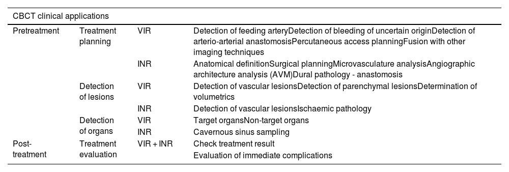
It is important to understand the functioning and clinical applications of CBCT to ensure its use is both careful and justified. The aim of this article is to review the main clinical applications of CBCT (in vascular interventional radiology and interventional neuroradiology). To this end, it focuses on pre-treatment applications (planning, lesion and organ detection) and treatment assessment. Table 1 lists all applications.
Summary of CBCT clinical applications pre-treatment (treatment planning, lesion and organ detection) and post-treatment (treatment evaluation), in both vascular interventional radiology and interventional neuroradiology.
| CBCT clinical applications | |||
|---|---|---|---|
| Pretreatment | Treatment planning | VIR | Detection of feeding arteryDetection of bleeding of uncertain originDetection of arterio-arterial anastomosisPercutaneous access planningFusion with other imaging techniques |
| INR | Anatomical definitionSurgical planningMicrovasculature analysisAngiographic architecture analysis (AVM)Dural pathology - anastomosis | ||
| Detection of lesions | VIR | Detection of vascular lesionsDetection of parenchymal lesionsDetermination of volumetrics | |
| INR | Detection of vascular lesionsIschaemic pathology | ||
| Detection of organs | VIR | Target organsNon-target organs | |
| INR | Cavernous sinus sampling | ||
| Post-treatment | Treatment evaluation | VIR + INR | Check treatment result |
| Evaluation of immediate complications | |||
AVM: pial arteriovenous malformations; CBCT: Cone-beam computed tomography; INR: interventional neuroradiology; VIR: vascular interventional radiology.
CBCT images are obtained in two stages: image acquisition (x-ray exposure and detection) and image reconstruction.7 During the acquisition, the C-arm is able to rotate 180–360° around the region of interest (that is positioned at the isocentre, the centre of the rotation). The projections from the rotational scan are transferred to the workstation to generate volumetric data, which is then processed and presented as continuous sequential slices. These images can also be visualised in multiplanar reconstructions (MPRs) and 3D reconstructions.
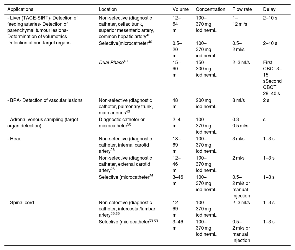
Contrast injection protocols (flow rate and volume) depend on acquisition parameters, the type of equipment used (diagnostic catheter/microcatheter), the intra-arterial location (main artery/selective catheterisation) and the clinical objective. In terms of the latter, if the objective is to confirm the feeding artery of a hepatic lesion, it cannot be ensured if the flow rate and volume of contrast are high and reflux into other arteries. However, if the goal is to identify arterio-arterial anastomosis, then higher flow rates and volumes will be necessary to saturate the vascular structures and highlight these connections. The authors' general recommendation is to perform an angiographic series prior to CBCT in order to determine the ideal flow rate and volume of contrast for the clinical indication. Table 2 summarises the contrast injection protocols for some specific clinical applications.
Summary of contrast injection protocols for specific clinical applications.
| Applications | Location | Volume | Concentration | Flow rate | Delay |
|---|---|---|---|---|---|
| - Liver (TACE-SIRT)- Detection of feeding arteries- Detection of parenchymal tumour lesions- Determination of volumetrics- Detection of non-target organs | Non-selective (diagnostic catheter, celiac trunk, superior mesenteric artery, common hepatic artery40 | 12–64 ml | 100–370 mg iodine/mL | 1–12 ml/s | 2–10 s |
| Selective(microcatheter40 | 0.5–20 ml | 100–370 mg iodine/mL | 0.5–2 ml/s | 2–10 s | |
| Dual Phase40 | 15–60 ml | 150–300 mg iodine/mL | 2–3 ml/s | First CBCT3–15 sSecond CBCT 28–40 s | |
| - BPA- Detection of vascular lesions | Non-selective (diagnostic catheter, pulmonary trunk, main arteries43 | 48 ml | 200 mg iodine/mL | 8 ml/s | 2 s |
| - Adrenal venous sampling (target organ detection) | Diagnostic catheter or microcatheter58 | 2–4 ml | 100–370 mg iodine/mL | 0.3–0.5 ml/s | s |
| - Head | Non-selective (diagnostic catheter, internal carotid artery26 | 18–69 ml | 100–370 mg iodine/mL | 3 ml/s | 1–3 s |
| Non-selective (diagnostic catheter, external carotid artery26 | 12–46 ml | 100–370 mg iodine/mL | 2 ml/s | 1–3 s | |
| Selective (microcatheter26 | 3–46 ml | 100–370 mg iodine/mL | 0.5–2 ml/s or manual injection | 1–3 s | |
| - Spinal cord | Non-selective (diagnostic catheter, intercostal/lumbar artery39,69 | 12–69 ml | 100–370 mg iodine/mL | 2–3 ml/s | 1–3 s |
| Selective (microcatheter39,69 | 3–46 ml | 100–370 mg iodine/mL | 0.5–2 ml/s or manual injection | 1–3 s |
BPA: balloon pulmonary angioplasty; CBCT: cone-beam computed tomography; SIRT: selective internal radiation therapy; TACE: Hepatic transarterial chemoembolisation.
Although the basic acquisition principle is the same for all CBCT devices, there are differences between manufacturers in terms of acquisition methods and parameters (DynaCT by Siemens, Erlangen, Germany; XpertCT/VasoCT by Philips, Eindhoven, The Netherlands; Innova CT by GE Healthcare, Chicago, USA; etc.).8 For example, there may be variations, which are generally preset, between the type of exposure (pulsed or continuous), the C-arm rotation angle and the exposure parameters (field of view [FOV], kilovolts, milliamps per second). Achieving a balance between radiation dose and image quality requires a clear understanding of the equipment’s acquisition protocols, parameters, and specific clinical needs. Working closely with the applications specialist is crucial to establishing the most suitable protocols for each application.
The acquisition parameters and other considerations (such as the region of study or patient size) can affect the radiation dose. Exposure levels should be monitored, ensuring that CBCT doses remain as low as reasonably achievable. In 2017, the European Federation of Organisations in Medical Physics (EFOMP) published its guidelines on CBCT quality control, recommending an annual review of equipment to ensure the image parameters are calibrated and radiation exposure is checked.9
Clinical applicationsPre-treatment applicationsVascular or percutaneous planningVascular and interventional radiologyCBCT offers a more detailed anatomical assessment than DSA, enabling the identification of several entities including tumour-feeding arteries, damaged arteries (active bleeding), and arterio-arterial anastomosis.
For example, in patients with hepatocellular carcinoma (HCC), CBCT can identify the feeding arteries and facilitate selective catheterisation. Therefore, in 2012 we assessed the contribution of CBCT during a hepatic transarterial chemoembolisation (TACE). The patients who underwent CBCT-assisted TACE resulted in significantly higher overall survival rates (p = 0.005) and local progression-free rates (p = 0.003) compared to those who underwent TACE with feeding artery selection by DSA. Furthermore, the multivariate analysis demonstrated that intraprocedural CBCT was an independent factor associated with higher overall survival and greater progression-free survival.10
CBCT’s ability to identify feeding arteries has led to its inclusion in the Standards of Practice on Hepatic Transarterial Chemoembolisation by the Cardiovascular and Interventional Radiological Society of Europe (CIRSE).11 This European guidance document recommends performing an initial non-selective CBCT with contrast administered via the common hepatic artery during TACE procedures for treatment planning, followed by one or more selective CBCTs to confirm the optimal injection site for the treatment.
Pung et al. carried out a meta-analysis in 2017 to evaluate the role of CBCT in TACE, in which they highlight how in addition to providing data on vascular anatomy, CBCT enables the identification of hidden lesions and extrahepatic vascularisation. Complementary information provided by CBCT brought about changes to the way 28% of patients were managed, both in terms of diagnosis and treatment.12
CBCT is used in emergency situations involving patients with arterial bleeding in order to identify the injured artery, enabling rapid haemorrhage control while reducing the number of acquisitions and overall procedure time.13,14 In 2015, Carrafiello et al. assessed 20 patients with active arterial bleeding. CT angiography (CTA) was used to evaluate multiple locations where contrast extravasation had not been detected on the initial DSA. The CBCT study was performed with the administration of contrast in the same artery as in the initial DSA and yet it detected bleeding in 19 of the 20 cases (95%).15
When the source of bleeding is unknown (where the exact artery responsible cannot be precisely located using DSA), CBCT can serve as an effective diagnostic alternative. In 2018, Grosse et al.14 evaluated the use of CBCT in 16 patients with active bleeding of uncertain origin, whose previous CTA and DSA scans had failed to detect the source. Two readers analysed the CTA, DSA and CBCT images. CBCT was more reliable in detecting the bleeding artery compared to the other two methods. Inter-observer agreement was moderate for CTA and DSA, and good for CBCT. Moreover, the mean radiation dose for CBCT was greater than for DSA (4.675 µGy·m2 vs. 3.721 µGy·m2), though this was not statistically significant. According to these results, CBCT was more reliable in detecting source arteries of the bleeding with a higher inter-observer agreement than the others.
CBCT also aids the identification of arterial anastomosis which could rule out the planned treatment option. For example, in haemoptysis embolisations, there may be anastomoses between the bronchial territory and the supra-aortic trunks or spinal arteries. If these connections are present but not identified, the embolic material administered in the bronchial territory could reach the cerebrovascular or spinal area, potentially causing neurological impairments in the patient.
In both emergency and scheduled procedures, CBCT is recommended to avoid embolisation of non-target sites and to make procedures safer (Fig. 2).
. In A, a small suspicious artery runs vertically along the midline (red arrow in A), and spinal cord irrigation cannot be ruled out. In B-D, axial, coronal, and sagittal MIP reconstructions of the CBCT demonstrate that the artery running along the midline (red arrow) does not show spinal cord irrigation and is in fact a periosteal branch originating from the posterior branch of the lumbar artery. In C, foci of active bleeding are observed (blue circles in C), with higher resolution than DSA. DSA: digital subtraction angiography; CBCT: cone-beam computed tomography; MIP: maximum intensity projection.")
Example of CBCT use in emergency setting. Right retroperitoneal haematoma. In A, DSA from the right L3 lumbar artery, where foci of active arterial bleeding are evident (blue circles in A). In A, a small suspicious artery runs vertically along the midline (red arrow in A), and spinal cord irrigation cannot be ruled out. In B-D, axial, coronal, and sagittal MIP reconstructions of the CBCT demonstrate that the artery running along the midline (red arrow) does not show spinal cord irrigation and is in fact a periosteal branch originating from the posterior branch of the lumbar artery. In C, foci of active bleeding are observed (blue circles in C), with higher resolution than DSA.
DSA: digital subtraction angiography; CBCT: cone-beam computed tomography; MIP: maximum intensity projection.
The volumetric information obtained with CBCT provides a 3D map of the vascular anatomy and its relationship with adjacent structures, which also aids in the planning of percutaneous procedures. With the help of processing tools, it is possible to plan percutaneous access for lesion treatment. This includes those lesions that are not visible with direct fluoroscopy and which require ablative treatments, such as pulmonary or certain bone lesions.16,17 It is also possible to plan percutaneous embolisations when treating type II endoleaks18 or lymphatic duct embolisations.19
For the planning of percutaneous needle access, CBCT is performed at the start of the procedure. The advantage is that the CBCT image allows for precise planning of the needle's course, avoiding essential structures like arteries or nerves. After image processing, it is possible to project the planned needle trajectory onto the real-time fluoroscopy image20 (Fig. 3).
. In B, CBCT reconstructions of the planning and trajectory of the cryoablation needles targeting the aneurysmal bone cyst (orange circle). In C-D, percutaneous translumbar embolisation of type II endoleak. In C, axial image of CTA in the arterial phase showing an aortoiliac stent (blue arrow) with an endoleak image in the excluded aneurysmal sac (yellow arrow). In D, CBCT image used for planning and verifying the needle path for embolisation. In E-I, percutaneous embolisation of a pseudoaneurysm of the short branches of the left gastric artery. In E, axial image of CTA in the arterial phase showing a pseudoaneurysm (yellow arrow) at the site of splenectomy. In F, angiography from the left gastric artery, confirming the presence of a pseudoaneurysm (yellow arrow). Note the arterial tortuosity that prevents selective catheterisation and thus endovascular treatment. In G, CBCT image after contrast administration via peripheral venous access, for localisation of the pseudoaneurysm (yellow arrow) and planning of percutaneous treatment. In H, overlay of the planned needle trajectory from the CBCT onto the DSA image. Dashed blue arrow parallel to the percutaneous needle. In I, CBCT (with peripheral venous contrast) performed after the embolisation of the pseudoaneurysm, showing the needle trajectory and correct occlusion of the pseudoaneurysm (yellow arrow). DSA: digital subtraction angiography; CBCT: cone-beam computed tomography; MRI: magnetic resonance imaging.")
Examples of CBCT application for percutaneous procedural planning. A-B, ablative treatment of bone lesion. In A, coronal image of an MRI sequence with fat saturation showing an aneurysmal bone cyst in the right acetabulum (orange circle). In B, CBCT reconstructions of the planning and trajectory of the cryoablation needles targeting the aneurysmal bone cyst (orange circle). In C-D, percutaneous translumbar embolisation of type II endoleak. In C, axial image of CTA in the arterial phase showing an aortoiliac stent (blue arrow) with an endoleak image in the excluded aneurysmal sac (yellow arrow). In D, CBCT image used for planning and verifying the needle path for embolisation. In E-I, percutaneous embolisation of a pseudoaneurysm of the short branches of the left gastric artery. In E, axial image of CTA in the arterial phase showing a pseudoaneurysm (yellow arrow) at the site of splenectomy. In F, angiography from the left gastric artery, confirming the presence of a pseudoaneurysm (yellow arrow). Note the arterial tortuosity that prevents selective catheterisation and thus endovascular treatment. In G, CBCT image after contrast administration via peripheral venous access, for localisation of the pseudoaneurysm (yellow arrow) and planning of percutaneous treatment. In H, overlay of the planned needle trajectory from the CBCT onto the DSA image. Dashed blue arrow parallel to the percutaneous needle. In I, CBCT (with peripheral venous contrast) performed after the embolisation of the pseudoaneurysm, showing the needle trajectory and correct occlusion of the pseudoaneurysm (yellow arrow).
DSA: digital subtraction angiography; CBCT: cone-beam computed tomography; MRI: magnetic resonance imaging.
Furthermore, in contrast to DSA, CBCT has the advantage of its ability to fuse with other image techniques such as ultrasound, computed tomography (CT) or magnetic resonance imaging (MRI).21,22 In routine practice, one of the procedures where fusing CBCT with CT in the angiography suite has proved useful is in the endovascular treatment of aortic aneurysms. In 2017, Goudeketting et al. carried out a meta-analysis to assess 3D image fusioning in endovascular aortic repair. They concluded that procedures which had used image fusioning were associated with a significant reduction in the volume of contrast used. In the case of endovascular aortic repair procedures, the 3D image fusion technique revealed a significant decrease of 40 ml in the volume of contrast used, which can be important in patients who are older or suffer from renal failure.22
The post-processing images obtained with CBCT can also be fused with DSA in real time. In the case of pulmonary angioplasty for the treatment of chronic thromboembolic pulmonary hypertension, the vascular map obtained with CBCT reduces procedure time and enhances the safety profile of pulmonary angioplasty, compared to using only guidance from DSA.23 Pulmonary angioplasty is a complex procedure, as multiple segmental pulmonary arteries are treated in each session. Some vascular lesions have poor angiographic visibility and the treatment area is not static due to the patient's breathing. CBCT makes it possible to accurately identify target lesions susceptible to angioplasty and create a 3D vascular map, which can be overlaid on the fluoroscopic image in real time24 (Fig. 4).
. In C, 3D volumetric reconstruction of the image acquired by CBCT, enabling treatment planning and highlighting the arteries to be treated. In D, overlay of highlighted arteries from the 3D image onto the real-time DSA. In E-G, different types of distal chronic pulmonary thromboembolic lesions visualised by CBCT. In E, band in the medial segmental artery of the middle lobe (circle). In F, occlusion of the left lower lobe artery (yellow arrow). In G, ring-shaped stenosis in the right upper lobar artery (yellow arrow). CBCT: cone-beam computed tomography; CT: computed tomography; DSA: digital subtraction angiography.")
Examples of CBCT application for pulmonary angiography. In A, images of pulmonary angiography with conventional CT and in B with CBCT of same patient, showing improved characterisation of chronic thromboembolic lesions in the distal segmental and subsegmental branches of the arterial tree (white arrows in A and B). In C, 3D volumetric reconstruction of the image acquired by CBCT, enabling treatment planning and highlighting the arteries to be treated. In D, overlay of highlighted arteries from the 3D image onto the real-time DSA. In E-G, different types of distal chronic pulmonary thromboembolic lesions visualised by CBCT. In E, band in the medial segmental artery of the middle lobe (circle). In F, occlusion of the left lower lobe artery (yellow arrow). In G, ring-shaped stenosis in the right upper lobar artery (yellow arrow).
CBCT: cone-beam computed tomography; CT: computed tomography; DSA: digital subtraction angiography.
Due to its high spatial resolution, CBCT has been increasingly used in necrecent years in the planning of endovascular, surgical or radiosurgical treatment of cerebrovascular pathology, whether brain aneurysms, pial arteriovenous malformations (AVMs) or dural arteriovenous fistulas (DAVFs).
In intracranial aneurysms, CBCT’s higher resolution and image quality, compared to 3D rotational DSA,25,26 make it the preferred technique when detailed anatomical definition is required, both for the aneurysm and the surrounding branches. This occurs in aneurysms located in the anterior communicating complex, at the basilar artery or internal carotid artery bifurcation, where there may be small perforating arteries that emerge close to the neck of the aneurysm (Fig. 5).27
 or only with a reconstruction adjusted to the aneurysm (C, D). In the reconstruction adjusted to the aneurysm (C, D) the origin and trajectory of the subcallosal (red arrow) and orbitofrontal (orange arrow) arteries are more clearly demonstrated than in the full volume reconstruction (A, B). CBCT: cone-beam computed tomography.")
Examples of the CBCT study detecting perforating arteries in the neck, and adjacent to the aneurysmal neck. In A, B, C and D, patient with ruptured saccular aneurysm in the anterior communicating complex. 3D angiographic reconstructions of the entire acquisition volume (A, B) or only with a reconstruction adjusted to the aneurysm (C, D). In the reconstruction adjusted to the aneurysm (C, D) the origin and trajectory of the subcallosal (red arrow) and orbitofrontal (orange arrow) arteries are more clearly demonstrated than in the full volume reconstruction (A, B).
CBCT: cone-beam computed tomography.
With the same CBCT acquisition and therefore the same FOV, you can generate images with a higher resolution producing reconstructions with a small volume of interest limited to the area to be analysed (Fig. 5).26 CBCT also helps characterise the neck of the aneurysm and can more accurately separate arteries that are in contact with the aneurysm and simulate a larger neck in the contact area (Fig. 6). This information is very useful as it can change both the approach (surgical-endovascular) and the use of devices designed to treat wide neck aneurysms endovascularly (remodelling balloons, intracranial stents, etc.).
 in the selective angiography of the right internal carotid artery (A) and in the 3D angiographic reconstruction (B). The 3D angiographic reconstructions show the likely wide neck of the aneurysm (red circle in C) and the possible adhesion of the lower bifurcation of the right middle cerebral artery to the aneurysm (red circle in D). In the MIP reconstructions, the existence of a narrow neck of the aneurysm is demonstrated (green circle in E), and the presence of a hypodense band between the lower bifurcation of the middle cerebral artery and the aneurysm is seen (green circle in F), indicating less adhesion between these elements. In G-J, patient with a ruptured aneurysm at the right middle cerebral artery bifurcation (white circle in G). In the 3D angiographic reconstructions of the CBCT, a lenticulostriate perforator (white arrow in H) is seen in contact with the surface of the aneurysm (yellow circle in H). In the MIP reconstructions of the CBCT, no hypodense band is seen between the lenticulostriate perforator (white arrow in I) and the surface of the aneurysm (yellow circle in I), indicating greater adhesion between these elements. After the aneurysm surgery, an ischaemic lesion is observed (red circle in J) as a result of the occlusion of the perforator during the manipulation and/or clipping of the aneurysm. CBCT: cone-beam computed tomography; MIP: maximum intensity projection.")
Example of CBCT use in aneurysms. In A-F, patient with a ruptured aneurysm at the bifurcation of the right middle cerebral artery and signs of severe vasospasm (arrows) in the selective angiography of the right internal carotid artery (A) and in the 3D angiographic reconstruction (B). The 3D angiographic reconstructions show the likely wide neck of the aneurysm (red circle in C) and the possible adhesion of the lower bifurcation of the right middle cerebral artery to the aneurysm (red circle in D). In the MIP reconstructions, the existence of a narrow neck of the aneurysm is demonstrated (green circle in E), and the presence of a hypodense band between the lower bifurcation of the middle cerebral artery and the aneurysm is seen (green circle in F), indicating less adhesion between these elements. In G-J, patient with a ruptured aneurysm at the right middle cerebral artery bifurcation (white circle in G). In the 3D angiographic reconstructions of the CBCT, a lenticulostriate perforator (white arrow in H) is seen in contact with the surface of the aneurysm (yellow circle in H). In the MIP reconstructions of the CBCT, no hypodense band is seen between the lenticulostriate perforator (white arrow in I) and the surface of the aneurysm (yellow circle in I), indicating greater adhesion between these elements. After the aneurysm surgery, an ischaemic lesion is observed (red circle in J) as a result of the occlusion of the perforator during the manipulation and/or clipping of the aneurysm.
CBCT: cone-beam computed tomography; MIP: maximum intensity projection.
In surgical planning for cerebral aneurysms, Hashimoto et al. suggest that CBCT may help visualise superficial veins that are important to the surgical approach. In their study, CBCT is compared with CTA to analyse the Sylvian veins and their tributaries in the pterional transsilvian approach in the treatment of cerebral aneurysms.28
Another important aspect of surgical planning is the analysis of the microvasculature around middle cerebral artery aneurysms, as these arteries are responsible for ischaemic complications.29 Matsushige et al. analyse the arteries in contact with the aneurysm and classify them based on the presence or absence of a hypodense band on the CBCT image between the artery and the aneurysmal sac, which reflects the degree of adhesion between the two structures. The neurosurgeon was able to completely separate 12 of the 17 arteries in which there was a hypodense band (minimal adhesion) (Fig. 6). He was, however, unable to separate any of the five arteries where no hypodense band was observed between the artery and the aneurysmal sac (more adhesion).25
CBCT is also useful in planning and neuronavigation during open surgery and in planning radiosurgery of AVMs, in which it is superior to methods such as MRI or CT.30–34 In the particular case of micro-AVMs (<1 cm), CBCT is especially useful, as it may be the only method capable of detecting them and carrying out treatment planning, given that they can go undetected by MRI.31,34 On the other hand, CBCT is inferior to MRI in delineating sulci and gyri, providing lower definition of the eloquent parenchymal areas near the lesion.
From an endovascular perspective, CBCT provides greater definition of the angiographic architecture of both the nidus and the arterial supply, as well as the venous drainage of the AVM, reducing the need for selective microcatheterisations to understand the lesion. Similarly, performing CBCT using a microcatheter during selective catheterisation can help clarify doubts about the presence of branches feeding into the AVM or supplying healthy parenchyma that may go unnoticed in DSA (Fig. 7).26
 and in axial T2 sequence MRI (yellow circle in B). The 3D angiographic reconstruction of the CBCT acquisition (reconstruction adjusted to the AVM) (C, D), as well as the segmentation and post-processing with software for 3D geometries (E, F), enable high-definition visualisation of the arterial supply. In these reconstructions, small feeding arteries to the AVM are identified (green arrow in C and black arrow in E), alongside small arteries supplying adjacent healthy tissue near the AVM")
Patient with an unruptured AVM in the right temporal region, seen in selective angiography of the right internal carotid artery (white arrow in A) and in axial T2 sequence MRI (yellow circle in B). The 3D angiographic reconstruction of the CBCT acquisition (reconstruction adjusted to the AVM) (C, D), as well as the segmentation and post-processing with software for 3D geometries (E, F), enable high-definition visualisation of the arterial supply. In these reconstructions, small feeding arteries to the AVM are identified (green arrow in C and black arrow in E), alongside small arteries supplying adjacent healthy tissue near the AVM's feeding arteries (yellow arrowhead in D and arrowhead in F).
AVM: arteriovenous malformation; CBCT: cone-beam computed tomography; MRI: Magnetic resonance imaging.
Furthermore, CBCT is particularly useful in dural pathology due to its ability to reveal dangerous anastomoses and small arterial contributions that are important in the endovascular treatment of DAVFs, chronic subdural haematomas, or meningiomas.26,35–38 With both cranial and spinal DAVFs, the exact localisation and anatomical delineation of the fistula is a challenge despite the use of CT, MRI, or DSA. In these cases, CBCT has proved to be a useful complement to DSA in the anatomical characterisation of DAVFs, both cranially and spinally (Fig. 8).26,39
. In B, selective angiography from a microcatheter placed in the left middle meningeal artery, where enhanced contrast uptake of the tumour is observed (yellow circle in B). In B, it is difficult to detect the petrosal branch (yellow arrowhead in B) of the middle meningeal artery that supplies the facial nerve, making this position unsafe for performing tumour embolisation with particles. In the CBCT study (C, D), it is easier to detect the petrosal branch (yellow arrowhead in C and D). In E-L, a patient with a dural fistula in the right sigmoid sinus (red square in F), the CBCT study provides greater definition of the exact site of the fistula (red square in G) to enable catheterisation of that point (red square in H). During embolisation, once the detected fistula site is occluded with coils (red circle in I), persistence of the arterialisation of the transverse sinus is observed (white arrow in I and J) and another fistula is seen in the angiography (yellow circle in I). The CBCT study enables us to determine the exact site of the fistula (yellow circle in J) and after placing the coil (yellow circle in K) the fistula is completely occluded (yellow circle in L). Neither the follow-up CBCT (K) nor follow-up angiography shows a fistula or arterialisation of the venous system. CBCT: cone-beam computed tomography.")
Example of CBCT use in dural pathology. In A-D, patient with a dural tumour lesion in the anterior portion of the left middle cranial fossa (yellow circle in A). In B, selective angiography from a microcatheter placed in the left middle meningeal artery, where enhanced contrast uptake of the tumour is observed (yellow circle in B). In B, it is difficult to detect the petrosal branch (yellow arrowhead in B) of the middle meningeal artery that supplies the facial nerve, making this position unsafe for performing tumour embolisation with particles. In the CBCT study (C, D), it is easier to detect the petrosal branch (yellow arrowhead in C and D). In E-L, a patient with a dural fistula in the right sigmoid sinus (red square in F), the CBCT study provides greater definition of the exact site of the fistula (red square in G) to enable catheterisation of that point (red square in H). During embolisation, once the detected fistula site is occluded with coils (red circle in I), persistence of the arterialisation of the transverse sinus is observed (white arrow in I and J) and another fistula is seen in the angiography (yellow circle in I). The CBCT study enables us to determine the exact site of the fistula (yellow circle in J) and after placing the coil (yellow circle in K) the fistula is completely occluded (yellow circle in L). Neither the follow-up CBCT (K) nor follow-up angiography shows a fistula or arterialisation of the venous system.
CBCT: cone-beam computed tomography.
The information provided by CBCT differs depending on the delay between contrast administration and the moment of image acquisition. If the delay is short, it provides data on arterial anatomy, whereas longer delay times make it possible to observe lesion and organ uptake and even venous anatomy (Table 2).40
CBCT enables the detection of vascular lesions. This application is particularly useful in chronic thromboembolic pulmonary hypertension as CBCT allows for the detection and characterisation of distal segmental and subsegmental disease, revealing abnormalities even in pulmonary segments with no pathology on ventilation/perfusion (V/Q) scintigraphy or CTA.3,41 Endovascular treatment is indicated for patients with distal thromboembolic disease inaccessible to surgery, making accurate characterisation at these levels essential.42 It also enables the identification and characterisation of the different types of chronic thromboembolic lesions at the distal level: occlusion, stenosis in rings/bands/webs and tortuous lesions.41,43 Band/web stenosis and ring stenosis are the lesions most likely to respond to angioplasty treatment and present fewer complications, while tortuous lesions and complete occlusions are generally more difficult to treat and present more complications24,44 (Fig. 4).
CBCT can also be used to detect parenchymal and even hypovascular lesions. This clinical application has been extensively studied in the intra-arterial treatment of liver lesions. In the absence of CBCT, hypovascular liver lesions were sometimes overlooked for endovascular treatments or were treated based on anatomical references, raising the risk of non-target or extensive embolisations, which are associated with a greater risk of complications and post-embolisation syndrome.
In 2016, Schernthaner et al. compared the visibility of hepatic metastases using CBCT and DSA, with pre-procedure MRI studies serving as the reference standard. CBCT in the late arterial phase demonstrated better detection of hypovascular lesions compared to both CBCT in the arterial phase and DSA.45
In the case of hepatic lesions supplied by multiple feeding arteries, the 3D data obtained through CBCT make it possible to determine the volume of the lesion supplied by each artery, which aids in the planning and segmentation of the doses used.46 This method, employed in selective internal radiation therapy (SIRT) for treating certain hepatic lesions, enables a more accurate distribution of the radiopharmaceutical dose—and thus the internal radiation—administered to each artery, based on the tumour volume perfused by each.47
Interventional neuroradiologyCBCT is useful in treatment planning for AVMs that are too small to be visualised or delineated in CTA/MRI,34 or DSA31 (Fig. 7).
CBCT can also detect small aneurysms (mycotic, traumatic, or blood blister-like) that are difficult to visualise in CTA/Magnetic Resonance Angiography (MRA) or DSA26,48 (Fig. 9). Moreover, it is extremely accurate in diagnosing severe angiographic vasospasm, particularly when it affects the mid and distal segments of the intracranial cerebral circulation, which can easily go unnoticed in DSA studies.49
 and the interpeduncular cistern (red circle in C). In the angiographic study, the blood blister-like lesion on the anterior aspect of the basilar artery is difficult to detect (yellow circle in E and yellow arrow in F). It is easier to detect and characterise the lesion in the CBCT study (yellow arrow in D). The axial reconstruction (white square in D) can differentiate between the basilar artery (yellow circle) and blood blister-like pseudoaneurysm (red irregular shape). In G-J, patient with acute occlusion of the basilar artery (white circle in G), which was recanalised after mechanical thrombectomy and placement of an intracranial stent, to address the atheromatous stenosis of the middle third (white arrow in H). The CBCT study enables an assessment of the condition of the perforating arteries of the basilar artery after stent placement (red circle in I and J). CBCT: cone-beam computed tomography.")
Example of CBCT use in posterior circulation. In A-F, patient with subarachnoid haemorrhage centred in the pontine cistern (red circle in A and B) and the interpeduncular cistern (red circle in C). In the angiographic study, the blood blister-like lesion on the anterior aspect of the basilar artery is difficult to detect (yellow circle in E and yellow arrow in F). It is easier to detect and characterise the lesion in the CBCT study (yellow arrow in D). The axial reconstruction (white square in D) can differentiate between the basilar artery (yellow circle) and blood blister-like pseudoaneurysm (red irregular shape). In G-J, patient with acute occlusion of the basilar artery (white circle in G), which was recanalised after mechanical thrombectomy and placement of an intracranial stent, to address the atheromatous stenosis of the middle third (white arrow in H). The CBCT study enables an assessment of the condition of the perforating arteries of the basilar artery after stent placement (red circle in I and J).
CBCT: cone-beam computed tomography.
In ischaemic pathology, the main use of CBCT is the detection of haemorrhagic complications in patients with ischaemic stroke after endovascular treatment.50 In recent years it has been increasingly used in the selection of stroke patients for mechanical thrombectomy, whether through non-contrast CBCT,51 perfusion studies52 or collateral analysis.53
It can reveal the ulceration of an atherosclerotic plaque, both extracranially and intracranially, potentially serving as a diagnostic aid for patients with acute ischaemic stroke, where the cause of the cerebrovascular event remains undetermined.54,55
Organ detectionVascular and interventional radiologyContrast-enhanced CBCT highlights vascular perfusion in organs. Avoiding the administration of drugs and embolic material to non-target arteries is crucial to prevent complications. For example, in SIRT, arteries that supply non-target organs, such as the gastroduodenal artery (duodenum), right gastric artery, left gastric artery (stomach), or cystic artery (gallbladder), must be identified to prevent complications such as gastroduodenal ulcers or radiation-induced cholecystitis.56 (Fig. 10).
 on a HCC located in the left hepatic lobe. A, diagram of the patient")
Examples of CBCT application for assessing the perfusion of ‘non-target’ and ‘target’ organs. In A-D, endovascular treatment (SIRT) on a HCC located in the left hepatic lobe. A, diagram of the patient's vascular anatomy, showing an anatomical variation where the left hepatic artery (red arrow) originates from the left gastric artery (white arrowhead), with perfusion of the gastric fundus (orange circle). The hepatic lesion is represented by yellow dashed lines. B, DSA from the left gastric artery (white arrowhead), from which gastric perfusion (orange circle) and perfusion of the hepatic lesion (yellow dashed lines) are observed. C, selective DSA from the left hepatic artery (red arrow) with perfusion of the hepatic lesion (yellow dashed lines). To ensure that the administration of the radiopharmaceutical from the left hepatic artery does not reach the gastric fundus (non-target organ embolisation), a CBCT is performed (D), which reveals the hypervascular hepatic lesion (yellow dashed lines), with no gastric uptake (orange line). E-F, CBCT application for adrenal venous sampling. E, diagram of the complex adrenal vein anatomy. F, phlebography from the right adrenal vein. G-H, axial and coronal reconstructions of the CBCT, where perfusion of the right adrenal gland is observed (orange circle), confirming the correct positioning of the catheter for sample collection. Diagrams A and E: the author.
CBCT: cone-beam computed tomography; DSA: digital subtraction angiography; HCC: hepatocellular carcinoma; SIRT: selective internal radiation therapy.
It is also useful to confirm that the vessels studied supply the target organ of interest. An example is adrenal venous sampling, where the complex venous anatomy and variability in the origin of the right adrenal vein complicate the technical success of the procedure (Fig. 10). A recent meta-analysis by Hafezi-Nejad et al.57 evaluated the technical success rate of the adrenal venous sampling procedure with and without CBCT. The authors found that the likelihood of technical success in procedures using CBCT was 5.5 times greater. This tool has proven to be especially useful for professionals with limited experience in adrenal venous sampling.58 Other examples of applications for organ identification include portal vein interventions59 or prostate embolisations,60 where vascular anatomical variations are common.
Interventional neuroradiologyThe primary use of CBCT is for cavernous sinus sampling in the evaluation of suspected cases of Cushing's syndrome. The position of the catheter and the venous drainage pattern influence the diagnostic performance of the test.61 Drainage from the cavernous sinus into the internal jugular vein via the inferior petrosal sinuses is classified into five types, and categorised as symmetrical if there is no variation in the drainage pattern between the two sides, and asymmetrical if there are different patterns.62
In cases where drainage from the cavernous sinus to the inferior petrosal sinuses occurs symmetrically, sampling from the latter has demonstrated correct lateralisation of the lesion in 86% of cases. However, in the context of asymmetrical drainage, correct lateralisation occurs in 44% of cases.63
In patients with asymmetrical cavernous sinus drainage, an alternative to inferior petrosal sinus sampling is to sample each half of the cavernous sinus. In this more selective test, CBCT can be useful both in selective catheterisation of each half of the cavernous sinus and in checking the position of the microcatheter.64
Evaluation of treatmentCBCT is especially useful in tumour embolisations, as suboptimal treatments could increase the likelihood of tumour progression or recurrence. For instance, in conventional TACE, a drug emulsion with iodised oil (lipiodol) is injected. Lipiodol is a radiopaque substance that has the characteristic of deposition in hypervascular liver tumours such as HCCs. Non-contrast CBCT enables assessment of the efficacy of conventional TACE intraoperatively by detecting iodised oil deposition in the lesion and in the adjacent parenchyma. It has been shown that tumour recurrence is significantly lower when there is a higher degree of iodised oil deposition in the lesion and a complete circumferential safety margin.65 In 2019, Bannangkoon et al. created a scale with three grades to define iodised oil disposition in the lesion and adjacent margins, based on CBCT after TACE65 (Fig. 11).
 deposition in the lesion and in the adjacent parenchyma. Grade A: iodised oil deposition in lesion and in surrounding parenchyma with complete safety margins. Grade B1: iodised oil deposition in lesion with incomplete safety margin. Grade B2: iodised oil deposition in lesion with no safety margin in surrounding parenchyma. Grade C1: iodised oil deposition incomplete in part of lesion. Grade C2: iodised oil deposition incomplete in centre of lesion. Data in table on local recurrence taken from Bannangkoon et al.65.")
Schematic representation of the degree of iodised oil (lipiodol) deposition in the lesion and in the adjacent parenchyma. Grade A: iodised oil deposition in lesion and in surrounding parenchyma with complete safety margins. Grade B1: iodised oil deposition in lesion with incomplete safety margin. Grade B2: iodised oil deposition in lesion with no safety margin in surrounding parenchyma. Grade C1: iodised oil deposition incomplete in part of lesion. Grade C2: iodised oil deposition incomplete in centre of lesion. Data in table on local recurrence taken from Bannangkoon et al.65.
In non-vascular procedures, it is sometimes difficult to guarantee the efficacy and accuracy of treatment with DSA imaging alone. In these scenarios, CBCT can also provide an immediate assessment of interventional treatment that is more accurate than 2D fluoroscopic imaging. For example, during the placement of colonic stents in patients with intestinal occlusion due to colorectal neoplasia, it allows verification of whether the stenosis has been successfully bypassed and whether the stent has correctly expanded and centred in the lesion. Likewise, in the case of placement of gastrojejunostomy tubes or internal and external urinary catheters, it helps to verify that they are correctly positioned in patients who have undergone previous surgeries.
CBCT also makes it possible to detect immediate procedure-related complications, avoiding the need to transfer the patient to a conventional CT suite, thus saving time and allowing faster implementation of treatment and management of complications.50,66
Interventional neuroradiologyThe principal use of CBCT in interventional neuroradiology is in verifying the correct placement of intracranial stents, having demonstrated its usefulness in both arterial67 and venous68 phases. Likewise, when checking intracranial stents, it is not only important to analyse whether the stent is adequately apposed to the vascular wall, but also whether the perforating arteries that have been covered are patent. This is especially important in intracranial atheromatous plaques, such as in the middle cerebral or basilar arteries. Fig. 9 shows an example of CBCT after recanalisation of the basilar artery and placement of an intracranial stent, showing patency of most of the perforating arteries.
In dural pathology, the location of the embolic material in the area of the fistula at both cranial (Fig. 8) and spinal level is an important predictor of the stability/durability of the treatment. A pilot study evaluated endovascular therapy in spinal dural fistulas and performed a pre- and post-treatment CBCT. All three patients whose post-treatment CBCT scan showed a satisfactorily distributed glue cast in the fistula improved clinically and had no clinical recurrence. In the case where satisfactory glue distribution was not achieved in the fistula, the patient did not improve clinically and the follow-up DSA showed recanalisation of the dural fistula.69
Advantages, disadvantages and future perspectivesOverall, CBCT is a safe technique that provides accurate images with good spatial representation. It also provides 3D imaging, with the possibility of carrying out reconstructions—whether MPR, maximum intensity projection (MIP), oblique or volumetric—and fusing them with other imaging techniques in real time. Artery or lesion identification and DSA overlay tools facilitate vascular navigation and percutaneous procedure planning. Furthermore, simulation programmes are available and an immediate evaluation of the procedure can be carried out.
One of its limitations is that it has a smaller FOV than MDCT, ranging from 0 to 25 cm for CBCT and 50–70 cm for MDCT. Another limitation is its high sensitivity to artifacts, especially motion artifacts (respiratory, cardiac, intestinal, etc.). Therefore, in chest and abdominal acquisitions, it is essential that patients are able to perform breath-holds, and in neuroradiology procedures, that they remain completely motionless. As a result, anesthesia plays a fundamental role in image quality. The patient's arms can also cause artifacts, so they should ideally be placed above the head for chest and abdominal scans. In order to achieve a balance between radiation dose and image quality, it is essential to understand the clinical applications of CBCT, acquisition parameters and contrast injection protocols. We recommend using it responsibly and becoming familiar with the situations in which CBCT can be a useful tool, provide additional information to the DSA, and make the procedure simpler and safer.
Although the basic principles underpinning CBCT will remain the same, future developments might seek to improve image quality (potentially broadening its applications), and reduce radiation dose and contrast.8 In terms of image acquisition and processing, future innovations might also increase speed and efficiency.
ConclusionsCBCT is a useful tool with multiple clinical applications, contributing to both treatment planning and assessment. Understanding how best to use it, its advantages, limitations and clinical applications can improve the accuracy and safety of endovascular and percutaneous procedures.
CRediT authorship contribution statement- 1
Research coordinators: ESA, JVJ, APC, MM, MWF, ALR
- 2
Study concept: ESA, ALR
- 3
Design: ESA, JVJ, APC, MM, MWF, ALR
- 4
Data collection: N/A
- 5
Data analysis and interpretation: N/A
- 6
Data processing: N/A
- 7
Literature search: ESA, JVJ, APC, MM, MWF, ALR
- 8
Drafting of article: ESA, JVJ, APC, MM, MWF, ALR
- 9
Critical review of the manuscript with intellectually relevant contributions: ESA, JVJ, APC, MM, MWF, ALR
- 10
Approval of the final version: ESA, JVJ, APC, MM, MWF, ALR
This project has not received any funding.