


Underground cable electrical parameters ZY as well as their modal propagation characteristics are highly frequency dependent which in certain cases turns its analysis difficult. To perform electromagnetic transient studies of cables the calculation of electrical parameters is essential to obtain the waves propagation solution through the multiconductor system. At the same time this requires to solve the inverse Laplace transform on a numerical form. Although the analytic Laplace transform has an indisputable accuracy, the application of its numerical version up-to-date has not been completely accepted. A complete methodology is developed in this work to guide analyst engineers or graduate students in the calculation of electromagnetic transients of underground cable systems. Finally, to help the validation of the numerical inverse Laplace transform a scaled prototype experiment is performed in the laboratory in which a transient step-response at the remote end of an energized conductor is measured.
Los parámetros eléctricos ZY de cables subterráneos y sus características de propagación modal son altamente dependientes de la frecuencia lo que en ciertos casos dificulta su análisis. Al realizar estudios de transitorios electromagnéticos en cables el cálculo de parámetros es primordial para obtener la solución de la propagación de ondas a través del sistema multiconductor. Esto a su vez requiere resolver la transformada inversa de Laplace en forma numérica. Aunque la transformada analítica de Laplace tiene una indiscutible precisión, la aplicación de su versión numérica no ha sido, hasta la fecha, totalmente aceptada. En este trabajo se desarrolla un metodología completa para guiar al ingeniero analista o estudiantes de posgrado al cálculo de transitorios electromagnéticos en sistemas de cables subterráneos. Finalmente, para ayudar a validar la transformada numérica inversa de Laplace se desarrolla en el laboratorio un experimento escalado prototipo, en el cual se mide la respuesta transitoria a un escalón de voltaje en el extremo receptor de un cable energizado.
An accurate calculation of electromagnetic (EM) transients on buried cable systems may take into account the Skin Effect in the ground and cable conductors, while relaxation effects on cable insulation layers (Wedepohl and Wilcox, 1973; Dommel, 1986; Marti, 1982; Marti, 1988; Uribe et al., 2002; Schellkunoff, 1934; Pollaczek, 1926; Uribe et al., 2004; Semlyen, 1985; Saad et al., 1996; Wedepohl, 1983). Consequently, the modal propagation functions of the cable system are highly influenced by the inductive loops formed between the power cables through the ground (Wedepohl and Wilcox, 1973). Thus, due to electromagnetic inductions phenomenon, the ground model is evaluated in this paper by means of two approaches for a qualitative comparison: the numerical solution of the exact Pollaczek’s integral and using the classical approximate formulas previously issued by Wedepohl, Ametani and Semlyen (Wedepohl and Wilcox, 1973; Dommel, 1986; Semlyen, 1985; Saad et al., 1996).
A benchmark model for calculating the voltage transient step-responses at the remote-end of a buried cable system is proposed in this paper (Wedepohl and Wilcox, 1973; Dommel, 1986). The transient step-response is synthesized in this paper through the Numerical Laplace Transform (NLT) (Uribe et al., 2002; Wedepohl, 1983).
Finally, the calculated responses are qualitative, validated here through a laboratory mesurement performed on a scaled prototype experiment.
A Benchmark case for the Electromagnetic Transient Analysis of Underground CablesThe voltage and current wave propagation in underground cable transmission systems is described by (Wedepohl and Wilcox, 1973; Dommel, 1986; Marti, 1982; Marti, 1988; Uribe et al., 2002):


where Z and Y are the series-impedance and the shunt-admittance matrices both in per unit length, respectively. The solution of (1a) and (1b) is (Wedepohl and Wilcox, 1973; Dommel, 1986; Marti, 1982; Marti, 1988; Uribe et al., 2002; Schellkunoff, 1934):
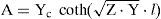
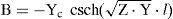
where

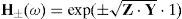
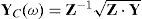
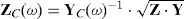
C1 and C2 are the integration constant vectors determined by the boundary conditions, H± is the transmission system propagation function, YC and ZC are the characteristic admittance and impedance matrices, respectively (Uribe et al., 2002).
An underground cable transmission system of length, l, as the one shown in Figure 1, can be represented by a two port network. A nodal admittance representation, relates the voltage and current responses from the sending end at z=0 to the remote end at z=l (Wedepohl and Wilcox, 1973; Dommel, 1986; Marti, 1982; Marti, 1988; Uribe et al., 2002; Schellkunoff, 1934):
and where V0(s) and I0(s) are the voltage and current vectors at the sending-end of the line z=0. Vl(s) and Il(s) are vectors of voltages and currents at remote-end of the transmission line or, in this case, cable system z=l.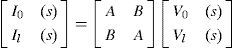
, a) cable system layout, b) cable physical dimensions and material properties")
Underground cable transmission system reported in Wedepohl and Wilcox (1973), a) cable system layout, b) cable physical dimensions and material properties
The flat buried cable system shown in Figure 1a formed three coupled loops between cables through the ground. In addition, each cable (as shown in Figure 1b) formed internal and external loops between the nucleus and the sheath, respectively. The internal loop is due to the impedances of the nucleus, EP insulation and the internal sheath, while the external loop if due to the impedances of the external sheath, the PVC jacket and the ground (Wedepohl and Wilcox, 1973).
A well known expression for calculating the nucleus impedance of a cylindrical cable conductor is (Wedepohl and Wilcox, 1973):
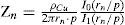
Where I0 and I1 are the zero and first order modified Bessel functions, p is the skin-effect layer thickness and the other variables are defined at the nomenclature.
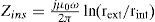
The insulation impedances between two contiguous cylindrical cable conductors with radii rext and rint as shown in Figure 1b are given by (Wedepohl and Wilcox, 1973):
The internal, external and mutual impedances of the tubular sheath conductor are given by the Schellkunoff theory for cylindrical formulae (Schellkunoff, 1934):
where ςint = rs-i / p, ςext = rs-e / p and the wornskian is W = K1(ςint) × I1(ςext) – K1(ςext) I1 (ςint).
The ground return impedances ZG(ω) are calculated in this paper through two different approaches for a qualitative comparison purpose.
The first approach is obtained solving the Pollaczek’s integral numerically and the second is obtained using classical closed-form approximations (Dommel, 1986; Uribe et al., 2004).
First, the Pollaczek’s integral is solved with the efficient, accurate and reliable algorithmic strategy proposed in Uribe et al. (2004). For comparison, the direct numerical integration is implemented here by using the adaptive Gauss-Lobatto quadrature routine, quadl, available from Matlab® v7 (Gander and Gautschi, 2000).
Then the closed-form solutions previously issued by Wedepohl, Ametani and Semlyen are also implemented in this paper to verify their application accuracy ranges (Wedepohl and Wilcox, 1973; Dommel, 1986).
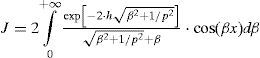
On assuming a Quasi-TEMZ propagation mode, the self and mutual ground-return impedance ZG(ω) of the cable system are given by (Wedepohl and Wilcox, 1973; Pollaczek, 1926; Uribe, 2004):
and
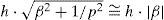
where J is the Pollaczek’s integral, β is the dummy variable and the other variables are listed in the nomenclature. The combination of regular and irregular oscillations due to the complex exponential factors in (5b) provokes convergence problems when applying generic quadrature routines at certain physical variable application ranges (Uribe et al., 2004).
On introducing in (5b) the variable change β = u/|p| and the following defined dimensionless parameters, we obtain
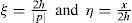
and after some algebraic manipulations, we have
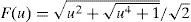
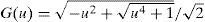
where and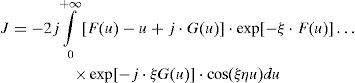
Basically, the algorithmic strategy proposed in Uribe et al. (2004) is based on two aspects; a pure damping exponential truncation criterion and on a zero crossings identification procedure for harmonic oscillatory functions in (6a).
To implement the direct numerical integration of Pollaczek’s integral (5b) may be transformed into:
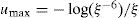
The truncation criterion for (7a) is based on the properties of the damping exponential factor in (6a) when F(u) → u. Thus, for the second factor in (6a) the entire range of u can be split-up into:
where erel is the relative error defined in this paper as: with a truncation limit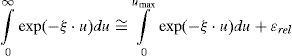

After Pollaczek’s mathematical statement in 1926, electrical engineering researchers have looked forward for many years of closed-form approximations to ZG(ω) (Wedepohl and Wilcox, 1973; Pollaczek, 1926). Some of the most often used in EMTP applications are the ones proposed by Wedepohl, Ametani and Semlyen.
Wedepohl and Wilcox (1993) presented a formula for calculating the self and mutual ZG(ω) valid for cables buried at usual depths around h≤1m, d≤1m and |x/p|<1/4:
where γ is the Euler constant.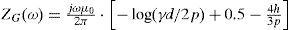
Another important approximation is the one implemented in the cable constants routine of the EMTP program (Dommel, 1986). Basically here, Ametani replaces Pollaczek integral by the one of Carson, assuming in (5b) the following consideration (Dommel, 1986):
Around 1982, Wedepohl conjectured a formula for calculating the self ZG of a buried conductor. The formula is based on the complex depth penetration of the electromagnetic fields in the ground. Subsequently, in 1985 Semlyen reported the following formula (Semlyen, 1985):
where rPVC is the external cable radius (Figure 1b), over the outer insulation PVC (Polyvinyl chloride) jacket.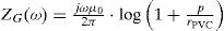
In addition, Saad, Gaba and Giroux published a very interesting closed-form approximation to Pollaczek integral based in the complex ground return plane and in the Cauchy’s integral theorem solution (Saad et al., 1996). The derivation process of this formula is very similar to the early one employed to obtain a simplified model of the Carson’s integral for calculating ZG of aerial lines (Dommel, 1986):

The self and mutual ground impedances ZG for each of the current loops formed between the buried cable system in Figure 1, are calculated in this paper by solving numerical Pollaczek integral and by using the above closed-form approximations.
It can be seen in Figures 2 and 3, that in both impedance calculations the closed-form approximations as well as the direct numerical quadrature of Gauss/Lobatto are in good agreement with the algorithmic solution developed by Uribe et al. (2004) used in this paper to establish a benchmark for calculating ZG(ω).
 for each cable in Figure 1a calculated with Pollaczek (5a) and with approximated formulas. The relative errors for these approximations are also shown in the small square of each figure, a) resistances, b) inductances")
Self ZG(w) for each cable in Figure 1a calculated with Pollaczek (5a) and with approximated formulas. The relative errors for these approximations are also shown in the small square of each figure, a) resistances, b) inductances
 between cables shown in Figure 1a calculated with Pollaczek (5a) and approximated approaches. Relative error details are also shown in the upper corner of each figure, a) resistances, b) inductances")
Mutual ZG(w) between cables shown in Figure 1a calculated with Pollaczek (5a) and approximated approaches. Relative error details are also shown in the upper corner of each figure, a) resistances, b) inductances
However, there are practical engineering cases when the distance between cables x (Figure 1) is considerably long, or when the cable trench is surrounded by soil with a very low resistivity (Dommel, 1986).
Appendix I shows the calculated mutual external loop of ZG(w) for the buried cable transmission system shown in Figure 1, but with a separation distance between cables of x=30m and with an homogeneous ground conductivity of σ=1S/m.
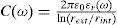
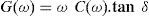
The dispersive dielectric effects of each cable insulation layer (better known as relaxation effects), are introduced into the electromagnetic transient analysis by the shunt admittance matrix, based in the following relation (Dommel, 1986):
where G(ω) is the shunt conductance which represents the Ohmic losses and C(ω) is the shunt capacitance which represents displacement current flowing between conductors through the specific dielectric. Assuming a concentric cable geometry, the capacitances are given by (Dommel, 1986): where εr(ω) = εr′(ω) – j · εr″(ω) is the frequency dependent complex permittivity, which has a vector relation to the loss tangent loss factor through the electrical conductances as follows (Dommel, 1986): where tan d is the insulation loss factor. Another option to evaluate the complex permittivity is to synthesize εr through a multi-term order Debye or Cole-Coles model (Dommel, 1986):
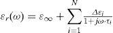
where ε∞ is the very high frequency permittivity value, N is the number of relaxation terms, τi′, used for the fitting, Δε = εs − ε∞ and εs is the static frequency permittivity value.
Modal propagation propertiesThe characteristics of wave attenuation and velocities are thus explained by The Theory of Natural Modes of Propagation by Wedepohl (Wedepohl and Wilcox, 1973; Dommel, 1986). The voltage and current wave propagation modes of the system are characterized by H±(ω) and ZC(ω) in equiations (2c) and (2e), respectively.
The propagation modes of the buried cable system in Figure 1 resemble approximations of the aerial modes of Clarke (Wedepohl and Wilcox, 1973; Dommel, 1986), where two types of modes can be identified. The metallic conductor (two differential modes) and the ground return. In addition, the presence of the conductor sheaths add even more combinations of these mainly two basic types of propagation modes.
Figure 4 shows the decreasing monotonic behavior of |ZC| and |e±√(ZY)-l| which have been evaluated with two different ZG(ω) models (Pollaczek and Wedepohl). The mode switching effect on H±(ω) has been removed by using the alternate method proposed by Wedepohl in (Wedepohl et al., 1996) for calculating transformation matrices tracking the order of eigenvectors and eigenvalues with their previous one corresponding frequency. The ZC of the system directly depends on the relation between frequency dispersion conductor effects and on the insulation relaxation effects of the cable.
 models for the benchmark cable system shown in Figure 1, a) magnitude of Zc, b) magnitude of exp (±√(ZY) ·l)")
Modal propagation functions calculated with Pollaczek and Wedepohl ZG(ω) models for the benchmark cable system shown in Figure 1, a) magnitude of Zc, b) magnitude of exp (±√(ZY) ·l)
In Figure 4a the influence of the ground-modes is noticeably greater for the metallic conductor loops according to the high inductive ZG(ω) at the low frequency range as seen in Figures 2b and 3b. It can be noticed from Figure 4b, that the propagation function depends on the product of the cable parameters ZY. Where the influence of the high inductive ZG(ω) is inversely related to the cable system modes. This can be corroborated from the Wedepohl model for ZG(ω) shown in Figures 2b and 3b, both according behavior in Figure 4b.
Frequency responseThe accurate calculation of ZY has been performed in the evaluation of parameter matrices A and B in (Equations 3a and 3b) with the Pollaczek and Wedepohl ground-return models. The nodal representation in (3a) is shown in Figure 5 where the cable system length l=40km. The open-circuit voltage and short-circuit current frequency responses are shown in Figure 6.

 open-circuit voltage response, b) short-circuit current response")
Frequency response for the two port network representation in Figure 5, a) open-circuit voltage response, b) short-circuit current response
The network elements connected to the transmission cable system are represented by generalized admittances in the sending end with Ys and in the remote end with YR.
The voltage at the remote end, Vl′, and the injected current at the sending end, Is′, are related to the boundary conditions as shown in Figure 5 (Uribe et al., 2002):
where

H(s) is the transfer function of the network system. Thus, the open-circuit voltage responses for the cable system in Figure 5 are calculated in the following paper section.
Numerical Laplace InversionThe voltage waveform response at the remote end of the cable system in Figure 5 is synthesized in this paper through the inverse NLT (Wedepohl and Wilcox, 1973; Wedepohl, 1983):
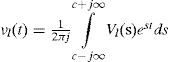
The discretization of (11a) leads to the numerical solution of Vz(t) at z = l where T = mΔt and WΩ = nΔs as follows (Uribe et al., 2002; Wedepohl, 1983):
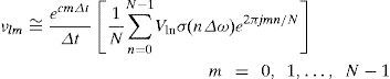
where N is the number of time samples and σn is the data window which is used for attenuating Gibbs phenomena errors (Wedepohl, 1983). The following Vonn Hann window is applied (Equation 11c).

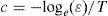
where Ω is the frequency truncated range. The frequency domain discretization of Vℓ(s) provokes frequency leaking in the time domain. The damping Laplace factor, c, is thus used to quench frequency leaking errors. However, since Gibbs error is not completely eliminated by data windows, it would be amplified by the undamping function, exp(cmΔt), in (11b). Thus, the selection of a value for c is a trade off. The following criterion has been proposed by Wedepohl (1983):
where T = NΔt is the observation time for the transient and e is the error level whose lower bound is determined by N. The discretization frequency step Δω at (11b) is implicitly considered as follows:
where NΔω/2 is the truncation frequency for the discrete representation of Vl(s). Consider now from (11c):
The left-hand side of (11f) is the sampling frequency while the right hand side is twice the truncation frequency. In addition (11f) agrees with the Nyquist sampling criterion.
Scaled prototype laboratory measurementsAn initial scaled experimental setup has been implemented in this paper to perform a qualitative comparison between the obtained voltage measurements in the labo-ratory and the NLT methodology. A thin wire of 1.302mm2 (16 AWG) for 600V with r = 1.25mm, h = 0.1m, ρcu = 1.72×10⁻⁴ Ω · m, ρg = 1000Ω · m (it is assumed that the laboratory has a solid rocky soil without moisture), and a cable length of l = 35m has been used for the scaled test.
A voltage source of 5V is switched at the sending end of the cable conductor as is shown in channel-1 of the oscilloscope obtained in Figure 7a. The transient step voltage response is measured with a TDS2024 oscilloscope at the remote end of the cable as is shown in channel-2 in the same figure.
 energization step-voltage at the sending end and its transient response at the remote end of the cable, b) measured and synthesized comparison (through the NLT) voltage transient step responses at the cable remote end")
In Figure 7b, the comparison between both measured voltages and the synthesized Laplace voltage response is illustrated having a good agreement. However, a small attenuation between both measured and synthesized voltage responses can be noticed in this figure. It is probably that the attenuation difference between both curves is due to a mistaken measurement taken from the ground resistivity of the laboratory.
ConclusionsAn accurate methodology for calculating ZY parameters for buried cable systems is developed in this paper. Ground-return impedances have been calculated here by solving the Pollaczek integral through direct numerical integration and with an algorithmic strategy proposed by the author.
The influence of approximate ground-return models on modal propagation functions is also discussed in this paper. The voltage transient step response on a single 16AWG prototype cable is measured on a scaled setup experiment. The voltage transient step response on the cable has been also synthesized through the Numerical Laplace Transform.
Both, the measured and the synthesized voltage transient step-responses are in good agreement. Thus, it is possible to suggest a qualitative validation for the NLT technique in power transient analysis applications.
Nomenclaturew = angular frequency (in rad/s) m0 = magnetic permeability of vacuum and air (H/m) = soil conductivity (S·m) = conductor resistivity for material “n” (Ω·m) = dimension-less material “n” relative permittivity = modified Bessel function of first class and “n” order = modified Bessel function of second class and “n” order = distance between cables, or the radius for the self impedance case (m) = distance between one cable and the image of the other, or twice the cable depth for the self impedance case (m) = complex depth of the Skin Effect layer thickness p 1/√(jωμ0σ) = cable depth, or h=(h1+h2)/2 for the mutual impedance case (m) = horizontal distance between cables, or the cable radius for the self impedance case (m) = underground cable core radius (m) = sending end or remote end of the transmission system (m) = transmission system length (m) = Laplace complex variable
Figure A1 shows mutual ZG(ω) calculated with Pollaczek algorithm (Uribe et al., 2004), Gauss/Lobatto quadrature routine (Gander and Gautschi, 2000), Ametani method (Dommel, 1986) and complex depth formula (Saad, Gaba and Giroux, 1996) for the buried cable system shown in Figure 1, with x=30m and σ=1S/m.
 resistance, b) inductance")
Mutual ground-return impedances for a buried cable system as the one shown in Figure 1 with x=30m and σ=1S/m, a) resistance, b) inductance
It can be noticed from this figure that closed-form approximations behaves well at certain ranges, while the same situation occurs with direct numerical integration which oscillates at certain h, r, x, σ and ω values. Thus, a general assessment of approximate methods of ZG(ω) is still missing.
Felipe Alejandro Uribe-Campos. Received the B. Sc. and M. Sc. degrees of Electrical Engineering, both from the State University of Guadalajara, in 1994 and 1998, respectively. During 2001 he was a visiting researcher at the University of British Columbia, B.C., Canada. In 2002 he received the Dr. Sc. degree of Electrical Engineering from the Center for Research and Advanced Studies of Mexico. The dissertation was awarded with the Arturo Rosenblueth prize. From 2003 to 2006 was a full professor with the Electrical Graduate Program at the State University of Nuevo Leon, México. From May 2006. He joined the Electrical Engineering Graduate Program at the State University of Guadalajara, México, where he is currently a full time researcher. Since 2004, he is a member of the National System of Researchers of Mexico. His primary interest is the electromagnetic simulation of Biological tissues for early Cancer detection and power system harmonic and transient analysis.