


This work is devoted to the velocity and acceleration analyses of a class of three-legged parallel manipulators. The input-output equations of velocity and acceleration are systematically obtained by resorting to reciprocal-screw theory. With the purpose to exemplify the application of the method, a case study is included. The example consists of solving the kinematics of a 3-CRS (Cylindrical + Revolute + Spherical) parallel manipulator. Furthermore, the numerical results obtained via screw theory are verified with the aid of commercially available software.
Este trabajo se dedica a los análisis de velocidad y aceleración de una clase de manipuladores paralelos compuestos de tres extremidades. Las ecuaciones entrada-salida de velocidad y aceleración se obtienen sistemáticamente recurriendo a la teoría de tornillos recíprocos. Con el propósito de ejemplificar la aplicación del método, se incluye un caso de estudio. El ejemplo consiste en resolver la cinemática de un manipulador paralelo tipo 3-CRS (Cilíndrico + Revoluta + Esférico). Más aún, los resultados numéricos obtenidos vía teoría de tornillos se verifican con la ayuda de software comercial.
Manipulators may be classified as serial, parallel or a combination of both, named hybrid mechanisms. A typical serial manipulator consists of an end-effector connected to the base link by means of a single kinematic chain, in which all the kinematic pairs play the role of active or motive joints. On the other hand, a typical parallel manipulator consists of an end-effector, namely the moving platform, connected to the base link, namely the fixed platform, by means of at least two kinematic chains or limbs. The presence of passive kinematic joints is a characteristic of parallel manipulators.
Without doubt, the most popular type of parallel manipulator is the so called Gough-Stewart platform. This non-redundant in-parallel manipulator consists of a moving platform and a fixed platform connected to each other by means of six extendible limbs or rods, where each limb is actuated independently providing six degrees of freedom to the moving platform. The parallel kinematic device is attributed to Gough (Gough, 1957; Gough and Whitehall, 1962) and, incorrectly, to Stewart (1965). These seminal contributions, a universal tire testing machine and a fly simulator, respectively, date back to the 1950s. Despite the indisputable and appreciable benefits of a Gough-Stewart platform such as rigidity and accuracy, one of its main drawbacks, due to the coupled kinematics over the moving platform, is the hazardous task for computing the forward position analysis. In fact, as it is reported by Raghavan (1993), the moving platform can reach up to forty locations when a set of generalized coordinates is given. The problem has been exhaustively addressed, see for instance (Innocenti and Parenti, 1990; Wen and Liang, 1994; Innocenti, 1995; Husty, 1996; Innocenti, 1998), providing excellent partial solutions. However, still in our days a closed-form solution for the forward position analysis seems to be an unrealistic task. Furthermore, limited workspace and a recurrent problem of singular configurations are the main drawbacks of most parallel manipulators. Recently, several robots for industrial purposes have been constructed based on the Gough-Stewart topology: Octahedral Hexapod HOH-600 (Ingersoll), HEXAPODE CMW 300 (CMW), Cosmo Center PM-600 (Okuma), F-200i (FANUC) and so far. These products exhibit an excellent performance, however one cannot ignore that this kind of parallel kinematic structures have a limited and complex-shaped workspace. Furthermore, their rotation and position capabilities are highly coupled and therefore the control and calibration of it are rather complicated demanding the implementation of sensors.
An option to overcome the limitations of Gough-Stewart platforms is the development of parallel manipulators with fewer than six limbs, preserving of course the six degrees of freedom. In this work the velocity and acceleration analyses, of a class of three-legged parallel manipulators are investigated by means of the theory of screws. The study is available for a wide range of parallel manipulators.
Description of the class of parallel manipulators under studyIt is known that the pose, position and orientation, of rigid body may be determined by knowing the position of three non-collinear points embedded to it (Merlet, 2004; Gallardo, 2014). Furthermore, it is straightforward to demonstrate that a minimum number of limbs may avoid the possibility of physical interference between the limbs, increasing the workspace of parallel manipulators. Thus the parallel manipulators considered in this study have the following features:
- •
The moving platform is connected to the fixed platform by means of three limbs.
- •
In order to simplify the mechanical assembly, avoiding additional conditions of manufacture, the moving platform is connected to the limbs by means of three spherical joints shaping an equilateral triangle.
- •
The limbs are connected to the fixed platform by means of revolute, cylindrical or prismatic joints.
- •
Overall, the parallel manipulators considered in the study are of the class 3-XYS, where {X, Y} ∈ {R, C, P} while S is a spherical joint where C, R, P and S stand for Cylindrical, Revolute, Prismatic and Spherical joint, respectively.
Some parallel manipulators meeting the characteristics above listed are the following: 3-RRS, 3-RPS, 3-CRS, 3-CPS, 3-RRRPS and 3-RRPS. Note that limited a non-redundant parallel manipulators are considered in the contribution.
Preliminary screw theoryAs a consideration for readers unfamiliar with the theory of screws, this section is devoted to review some elementary concepts of it.
In Plücker coordinates a screw, notated as $, is a six-dimensional vector given by $ = (s, sO), where s is named the primal of the screw, P ($) = s, and denotes the direction of the line. Usually the primal part is a unit vector of course alone the instantaneous screw axis (ISA). While sO is named the dual part of the screw, D ($) = sO, and it is the moment produced by vector around the reference pole O. The vector sO is calculated as follows
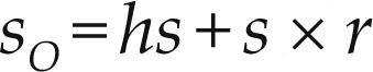
Therein h is the pitch of the screw while r is a vector directed from an arbitrary point of the ISA to the reference pole O. Conveniently, the reference pole is chosen as the origin of the reference frame in order to simplify the Plücker coordinates. In a revolute joint the pitch h vanishes yielding $ = (s, s × r), while in a prismatic joint the pitch goes to infinity yielding $ = (0, s). Furthermore, any lower kinematic pair may be modeled combining revolute and/or prismatic joints, e.g. a spherical joint may be modeled as three concurrent revolute joints while a cylindrical joint is modeled as the combination of one prismatic joint with one revolute joint.
The Lie algebra se(3) of the Euclidean group SE(3) is the set of elements of the form ($) = (s, sO). Let $1 = (s1, sO1), $2 = (s2, sO2) and $3 = (s3, sO3) be three elements of the Lie algebra se(3). Furthermore, consider that μ1, μ2, μ3 ∈ R. Concerned with the contribution, the Lie algebra supports the following operations:
Addition, $1 + $2 = (s1 + s2, sO1+sO2)
Multiplication by one scalar, μ$ = (μs,μsO)
Lie product, [$1 $2] = (s1 × s2, s1×sO2 – s2 × sO1)
Furthermore, the Lie product has the following properties
Nilpotent, [$1 $2] = 0
Distributive, [$1μ2 $2 + μ3 $3] = μ2 [$1 $2] + μ3 [$1 $3]
[μ1 $1 + μ2 $2 $3] = μ1 [$1 $3] + μ2 [$2 $3]
Jacobi identity, [$1 [$2 $3]] +
[$3 [$1 $2]] + [$2 [$3 $1]] = 0
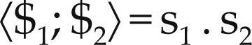
On the other hand the Lie algebra is endowed with two bilinear symmetric forms: the Klein form, notated as {*;*}, and the Killing form, notated as 〈*;*〉. The first one is defined as follows

therein the dot (.) denotes the inner product of three-dimensional vectorial algebra. While the second one is defined as follows
The representation of the kinematic states of a rigid body, as observed from another body or reference frame, has been a topic that has attracted the attention of kinematicians since many years ago. In fact, it dates back to the pioneering contribution of Ball (1900). The velocity state, or twist about a screw, of rigid body was defined by Ball (1900) as a six-dimensional vector given by
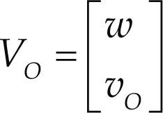
where w is the angular velocity vector of the body while vO is the linear velocity vector of a point O embedded to it. Almost four decades after the contribution of Ball, one representation of the acceleration state of rigid body, the logic next step, was proposed by Brand (1947) as follows
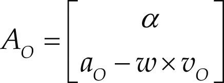
where α denotes the angular acceleration of the vector while aO denotes the linear acceleration vector of point O.
It is interesting to note that the primal part of the acceleration state is obtained directly as the time derivative of the primal part of the velocity state, i.e.
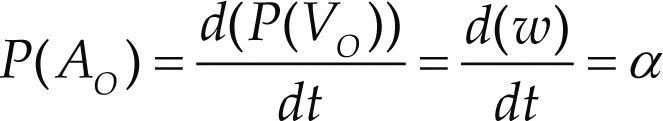
Thus, at this moment a natural question arises, why don’t occur the same for the dual part of the acceleration state? In other words, why D(AO) = aO – w × vO ≠d (D (VO)) / dt? The answer to this query can be found in the heart of the theory of helicoidal vector fields, for details the reader is referred to Gallardo et al. (2008).
Consider an open kinematic chain as shown in Figure 1, where adjacent bodies are connected by means of infinitesimal screws also known as helical pairs. The velocity state of the end-effector m as measured from the base link j may be expressed in screw form, see for instance Sugimoto and Duffy (1982), as a linear combination of the involved screws as follows
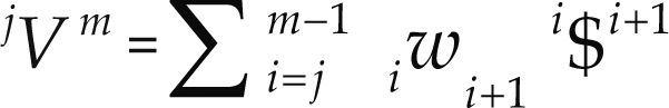

where kwk+ 1 denotes the k-th joint-rate velocity between adjacent bodies k and k + 1. By the time, the usefulness of Eq. (5) in robot kinematics was immediately recognized by engineers and scientists; however its extension to the acceleration analysis remained as an open problem for more than one decade. Certainly, the difficulty to express in screw form the acceleration state of kinematic chains was considered as one of the main drawbacks of the theory of screws. It was in 1996 when Rico and Duffy (1996) introduced the following equation
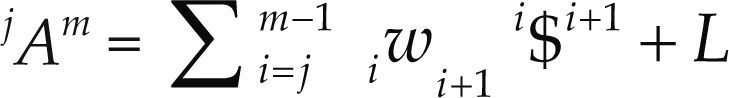
where w˙k+1k denotes the joint-rate acceleration between adjacent bodies, i.e. wk+1k=dkwk+1dt, while L named the Lie screw of acceleration and it is calculated according to the joint-rate velocities of the serial chain as follows
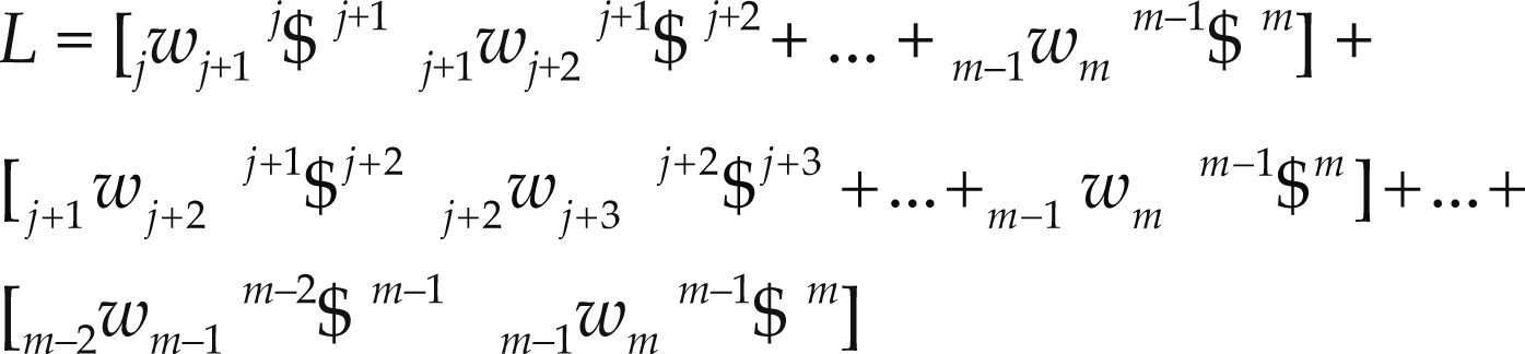
A closed kinematic chain may be considered as a serial manipulator where bodies m and j are joined forming thefixed platform, i.e. m = j. On the other hand, for clarity, unlike the equation of velocity state in screw-form, in the contribution the six-dimensional vector L is written explicitly. Equation (8) was named by Rico and Duffy (1996) as the reduced acceleration state.
Velocity analysisThe benefits of using screw theory in analyzing the infinitesimal kinematics of parallel manipulators are indisputable; see for instance (Rico and Duffy, 1996, 2000; Gallardo et al., 2003). In this subsection the velocity analysis of the family of parallel manipulators under study is carried-out by means of the theory of screws. To this end, the modeling of the screws of some parallel manipulators is depicted in Figure 2. It is important to mention that in the case of parallel manipulators with fewer than six degrees of freedom, in order to satisfy the dimension of the space spanned by the infinitesimal screws, it is necessary the introduction of virtual or fictitious screws into the mechanism. They are indicated with upper asterisks in Figure 2.

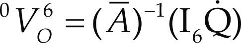
The velocity state of the moving platform, with respect to the fixed platform, may be written trough any of the i – th connector limbs, unless otherwise i = 1, 2, 3 in the rest of the contribution, of the parallel manipulator in screw form as follows

where the joint-rate velocity w3i2 is chosen as the i – th generalized speed. Naturally concerned with six-degrees-of-freedom parallel manipulators, e.g. the 3CPS robot, the designer must choose the complementary generalized speeds. Furthermore, note that the screws $i43 and $i54 are reciprocal to all the screws associated to passive joint rates in the same limb. Resorting to the Klein form, after a lengthy procedure the general input-output equation of velocity may be written as
where, as previously defined, 0V6 = (w, v) while Ā is named the first-order coefficients matrix of the manipulator which is computed according to the Jacobian matrix J=$143 $243 $343 $154 $254 $354 and an operator of polarity Δ= 0I3 as follows
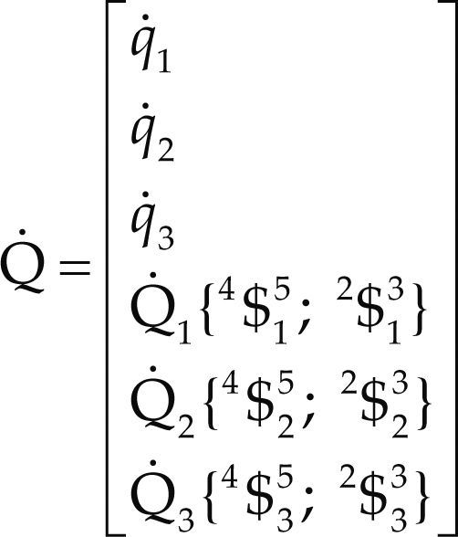
Furthermore,
Q˙=diag$143;$v $243;$v $343;$v $154;$v $254;$v $354;$v is a diagonal matrix named the first-order driver matrix of the manipulator.
The inverse velocity analysis consists of finding the generalized speeds given the velocity state 0V6. On the other hand, the forward velocity analysis consists of computing the velocity state 0V6 given a set of generalized speeds.
Acceleration analysisThe reduced acceleration state of the moving platform as measured from the fixed platform, the six-dimensional vector 0A6 may be written in screw form through the connector limbs as follows

where in order to compute the Lie screws of acceleration Li, see Eq. (9), the joint-rate velocities may be computed upon Eq. (10).
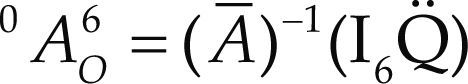
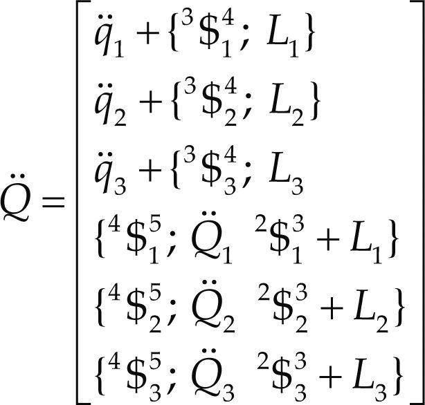
Following the trend of the velocity analysis, by resorting to reciprocal-screw theory the input-output equation of acceleration of the manipulator results in
where, as previously defined, 0A6 = (α; a – w × v) while Q¨=diag.I$14;$A $243;$A $343;$A $154;$A $254;$A $354;$A is a diagonal matrix named the second-order driver matrix of the manipulator. It is important to note that such matrix contains the Coriolis acceleration terms.
The inverse acceleration analysis consists of finding the generalized accelerations given the reduced acceleration state while the forward acceleration analysis consists of computing the reduced acceleration based on a set of generalized accelerations.
Case study: 3-CRS parallel manipulatorIn this section in order to show the application of the method, the velocity and acceleration analyses of a six-degrees-of-freedom parallel manipulator are reported.
The parallel manipulator at hand consists of a moving platform and a fixed platform connected to each other by means of three CRS-type limbs. In order to satisfy the six freedoms of the manipulator, the translational motions of the cylindrical joints and the revolute joints connecting the lower and upper links of the limbs are chosen as the six generalized coordinates of the mechanism (Figure 3), i.e. w1i0=q¯i and w3i2=Q˙i.

Using SI units thorough the numerical example, the spherical joints shape an equilateral triangle of side r = 0.5 while the axes uˆiof the cylindrical joints, expressed in the fixed reference frame XYZ, are given by uˆ1=−kˆ,uˆ2=−0.5ιˆ=0.866 kˆ,uˆ3=0.5ιˆ−0.866kˆ where ιˆ, jˆ and kˆ denote unit vectors associated to the X, Y and Z axes. On the other hand, the generalized coordinates are commanded to follow periodical functions given by q1 = 0.125sin (t), q2 = 0.2sin (t), q3 = 0.25sin2 (t), Q1 = 0.65sin (t) + 1.047, Q2 = 0.5236sin (t) + 0.35, Q3 = 0.5236sin (t) + 1.047 in the interval of time 0 ≤ t ≤ 2π, whereas in the reference configuration of the robot the nominal positions of the cylindrical joints, points notated as c1, are chosen as c1 = (0.5, 0, 0), c2 =(0.75, 0, – 0.433) and c3 = (0.25, 0, – 0.433). This implies that the instantaneous positions of the cylindrical joints are given by Ci = Ci=qiuˆi+ci which are located by vectors C→i. With these data it is required to compute the instantaneous velocity and acceleration of the center of the moving platform.
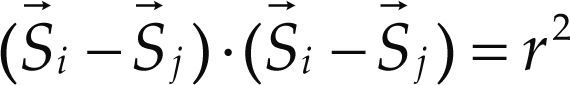
For the sake of completeness and as a necessary step to solve the infinitesimal kinematics in what follows the displacement analysis of the robot manipulator is presented. The forward displacement analysis consists of finding the coordinates of points Si= (Xi, Yi, Zi), located by vectors S→i, given the six generalized coordinates q1 and Q1. According to the distance di it is possible to write three closure equations as follows
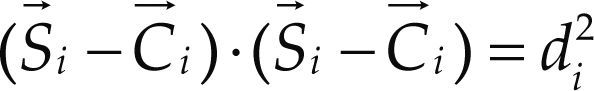
where . Furthermore three compatibility equations may be written based on the spherical joints as
On the other hand, the cylindrical joints constrain the motions of the spherical joints in such a way that

Equations (15)-(17) form a system of three linear and six non-linear equations in the nine unknowns Xi, Yi and Zi which is solved applying the Sylvester dialytic method of elimination, for details the reader is referred to Gallardo et al. (2008). At the time t = 0 one of the sixteen solutions obtained for the forward position analysis indicates that the coordinates of the centers of the spherical joints are given by S1 = (0.5, 1, 0), S2 = (0.6826, 1.2475, – 0.3941) and S3 = (0.25, 1, – 0.433). This solution is selected as the home position (reference configuration) of the parallel manipulator. After, according to Eq. (11) the velocity state of the moving platform is obtained as
where the first-order driver matrix of the mechanism is computed as
Thus the angular velocity vector of the moving platform is obtained as the primal part of the velocity state V060 while the velocity of the center of the moving platform is obtained as the dual part of the velocity state. It should be noted that the Plücker coordinates of the infinitesimal screws are computed considering the center of the moving platform as the reference pole. On the other hand, the reduced acceleration state of the moving platform, see Eq. (14), is found as
where the second-order driver matrix of the manipulator is given by
Hence, the angular acceleration of the moving platform is computed as the primal part of the six-dimensional vector V060. Furthermore, in order to compute the acceleration of the center of the moving platform consider that knowing the dual part of the reduced acceleration state it follows that
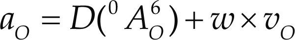
The formulae reported for the velocity and acceleration analyses were translated into a Maple8© sheet. Relevant procedures of the Maple sheet are as follows:
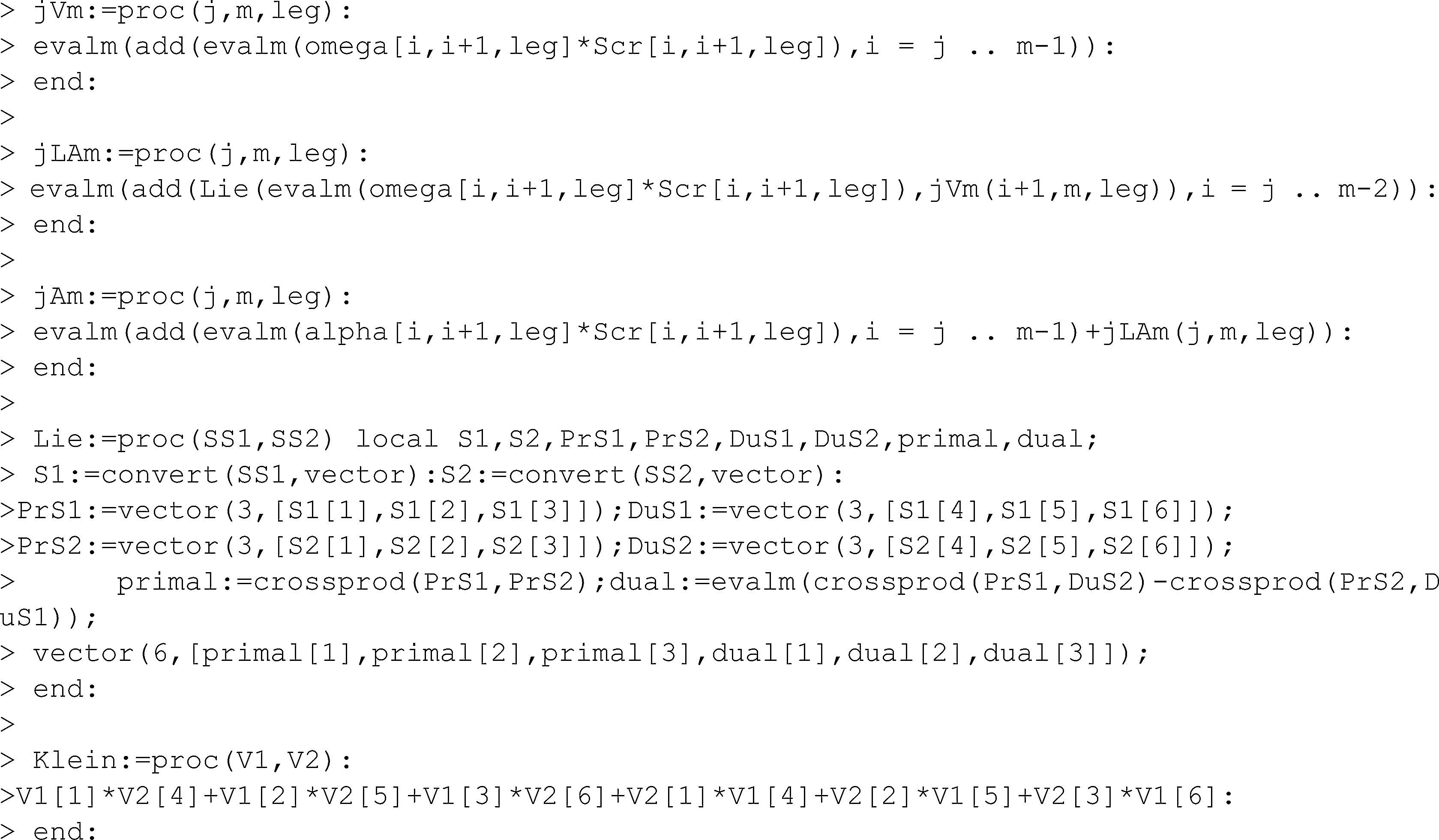
Let us consider that j and m are two in general no adjacent bodies of a serial kinematic chain, see Figure 1. The procedure jVm allows to compute the velocity state of m with respect to j whereas the procedure jLAm is devoted to compute the corresponding Lie screw of acceleration. Meanwhile, the procedure jAm is employed to compute the reduced acceleration state of m as observed from j. Finally, Lie and Klein are procedures to compute, respectively, the Lie product and the Klein form of two six-dimensional vectors.
The numerical results obtained by means of the theory of screws were verified with the aid of commercially available software like ADAMS©. The virtual prototype is shown in Figure 4. On the other hand, for clarity, the plots generated using both strategies are presented in Figure 5. In that concern, in order to avoid redundant notation, the labels of the right plots of Figure 5 were removed.

, using ADAMS© (right plots).")
Finally, it is worth to note that the numerical results obtained via screw theory are in excellent agreement with those generated using another approach such is the software ADAMS©, e.g., the corresponding plots matches exactly the same values when them are superposed.
ConclusionsIn this contribution the velocity and acceleration analyses of a family of three-legged parallel manipulators are investigated by means of the theory of screws. The velocity and acceleration analyses are approached using the theory of screws. The input-output equations of velocity and acceleration are systematically obtained by taking advantage of the Klein form of the Lie algebra se(3) of the Euclidean group SE(3). The concept of reciprocal screws plays a central role. In that regard, it is worth to note that concerned with the acceleration analysis the method does not require the computation of the passive joint-acceleration rates of the manipulator. The methodology of analysis is available for any three-legged parallel manipulator. In order to illustrate the potential of the methodology of analysis considered here, the infinitesimal kinematics of a 3-CRS parallel manipulator is solved with the aid of computer codes. Finally, the numerical results generated for the moving platform using the theory of screws, are compared with numerical results produced with special software of simulation like ADAMS©.
This work has been supported by the National Council of Science and Technology, Conacyt, of México.
Chicago style citation
ISO 690 citation style
Jaime Gallardo-Alvarado. Received the BSc and MSc degrees in mechanical engineering from Instituto Tecnológico de Celaya, México, in 1985 and 1988 respectively; and the Ph.D. in electrical engineering from Instituto Tecnológico de la Laguna, México, in 1999. He had authored/coauthored more than 40 journal papers and his interests cover spatial kinematics and dynamics of robotics systems using screw theory. Dr. Gallardo-Alvarado is a current full time professor at the Department of Mechanical Engineering of the Instituto Tecnológico de Celaya and He is a member of the National System of Researchers of México (SNI). He is member of the editorial board of the journals Advances in Robotics Research and The International Journal of Advanced Robotic Systems.