

PIFA antenna (Planar Inverted F Antenna) is one of the most used in mobile devices, fundamentally for it reduced size. Because of the convergence of wireless services in one mobile device, it is convenient that it can operate in different frequencies, leading to multiband antenna design. Nonetheless, besides technical consideration, it is necessary the evaluation of antenna radiation impact in the user. Therefore, in this work a dual-band PIFA antenna for GSM 900 and GSM 1800 is presented and its interaction with a model of user hand and head is analyzed and evaluated by means of SAR (Specific Absorption Rate) parameter in a simulated manner. The dual-band characteristic is obtained by means of an insertion of an L-shaped slot, which will use to tune the operation frequencies.
Las antenas PIFA (planar Inverted F Antenna) son una de las más empleadas en los dispositivos móviles, fundamentalmente por su tamaño reducido. Debido a la convergencia de los servicios inalámbricos en un solo dispositivo móvil, es conveniente que este pueda operar en diferentes frecuencias, lo que ha conducido al diseño de antenas multibanda. Sin embargo, además de consideraciones técnicas, es necesaria la evaluación de los efectos de la radiación de la antena en el usuario. Es por ello que en este trabajo se presenta una antena PIFA doble banda para GSM 900 y GSM 1800, y se analiza y evalúa su interacción con un modelo de mano y cabeza humanas por medio del parámetro SAR (Razón de Absorción Específica) de manera simulada. La característica de doble banda se obtiene por medio de una inserción de una ranura en forma de L, que será empleada para sintonizar las frecuencias de operación.
The vertiginous growth of the mobile wireless communications has leaded the development of small antennas with multiband behavior. In this moment, a terminal often integrates several wireless systems, and the antennas play a fundamental role in the best design of these. An appropriate design and an integrated radiator, not only permit a reliable connection, independently of the orientation of the terminal, but also it helps to foresee an excessive consumption of the battery, improving the efficiency. In addition, the design of the antenna must take into account the effects of the housing and antenna radiation interaction with the human body, with the objective to select the best design and location of the radiator in the terminal.
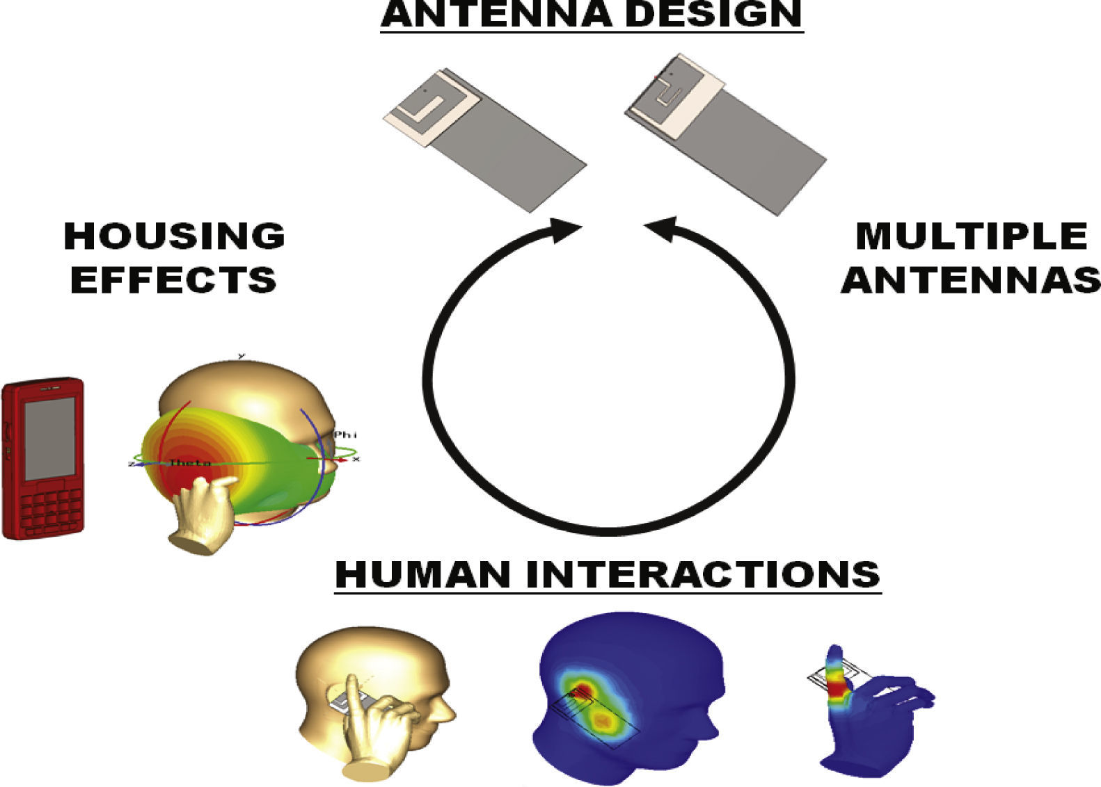
The implementation of an antenna is schematized in (Balanis, 2008) as a cyclical process where intervene four stages, as it is shown in Figure 1: antenna design, multiple antenna analysis, human interaction study, and housing effects; and it stops when the desired electromagnetic parameters are met. The present work will take into account mainly two stages: the design of the antenna and its interaction with a representative model of user (SAM, Specific Anthropomorphic Mannequin).

The studies and reports that have been carried out analyzing the impact of SAR are diverse, however do not exist data for all conditions that can be given. In (Firoozy & Shirazi, 2011) is presented a dual band PIFA antenna (1800 and 2442MHz), and is analyzed the SAR by means of CST MICROWAVE STUDIO (CST MWS) software simulation. In (SOH, VANDENBOSCH, OOI, & NURUL, 2011) a study of the behavior of PIFA antennas in a human body model was carried out, evaluating SAR in different parts of the user (chest and back). This work also evaluates the impact of the type of material to use as antenna. The multiband behavior is obtained with a U-shaped slot. In (Vehovský et al., 2014) a PIFA for the two bands of GSM with an L-shaped slot is presented, and it was built and tested a hand model for SAR evaluation. In (Liu & Zhao, 2014) a multiband antenna for a wide rank of frequencies of GSM900/ 1800/1900, UMTS2100 and LTE2300/2500 was designed, and was evaluated the SAR in the presence of a hand and head model. In (Lee & Sung, 2014) are also analyzed the values of SAR with a SAM model.
Based on the previous information, the paper presents the design of a dual-band PIFA antenna for the GSM900 (876-960MHz) and GSM1800 (1710-1889MHz) bands. The second resonant frequency and the dual-band behavior are obtained by means of the insertion of an L-shaped slot. This technique has been used in (Cabedo et al., 2009) and (Vehovský et al., 2014). The proposed design has as main advantage that the fine tune of the structure will be realized varying the width of the L-shaped slot inserted in the patch, rather than the patch dimension. For the PIFA design several criteria have been taken into account: confine the antenna in an extreme of the structure, and maintain as low as possible the height (vertical dimension). Moreover, the evaluation of the radiation influence in a model of user hand and head is carried out in a simulated manner. CST MWS software is used for the simulations.
Dual band PIFA antenna with L-shaped slotTo obtain good radiation characteristics, the antenna must be resonant and it size must be comparable with the wavelength. That is the reason for the introduction of several techniques directed to reduce the dimensions of the structure. The use of a PIFA antenna permits a reduction of at least the half of the size with respect to a basic microstrip antenna. This is successfully achieved by means of a shorting wall, and if its thickness is reduced a decreasing in frequency can be obtained. Some advantages of the PIFA antennas are compact size, low profile, easy construction and a good electric behavior.
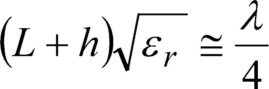
The fundamental parameters to adjust the PIFA design are the longitude of the patch (L and W), the height of the structure h, the width of the shorting wall w, and the distance from the feeding to the wall. The dimensions of the L, W and the h are chosen to achieve a certain resonant frequency as follow (García, 2007)
where
¿r = dielectric constant of the substrate between the patch and the ground plane
λ = free space wavelength.
If the wall is reduced to a shorting pin, the electromagnetic waves will travel a longer distance, for which the condition of resonance is transformed in
Several considerations obtained from diverse parametric studies will be taken to design a PIFA: the bandwidth of the PIFA increases with the h (as in the case of the conventional patch antenna), and the dimension of the patch regulate the resonant frequency (bigger patch, lower frequency). Also, the variations of parameters have been carried out (position of the shorting wall, position of the feeding, height of the layer of air) for tuning the structure.
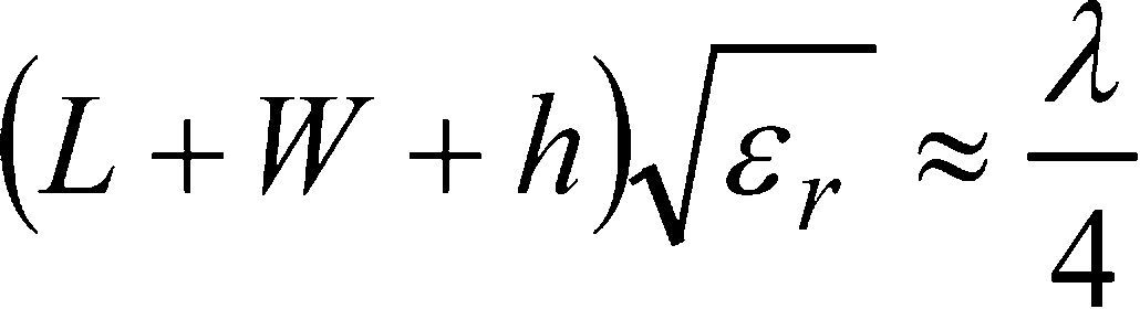
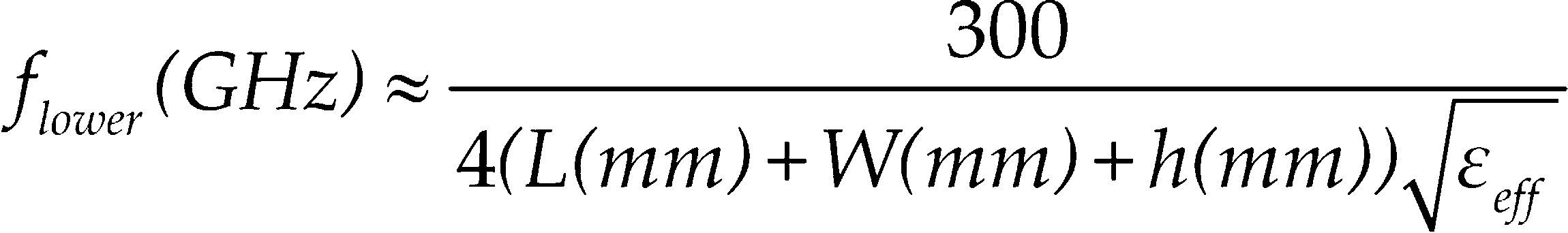
At the beginning, a patch that operates at GSM 900 band was designed, and the second frequency is excited with the insertion of the L-shaped slot with a length around λ/4 for GSM 1800 band. The approximate equation in practical units for the lower frequency is derived from equation (2)
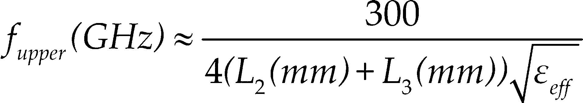
For the upper frequency is used the following equation, as is proposed in (Firoozy & Shirady, 2011)
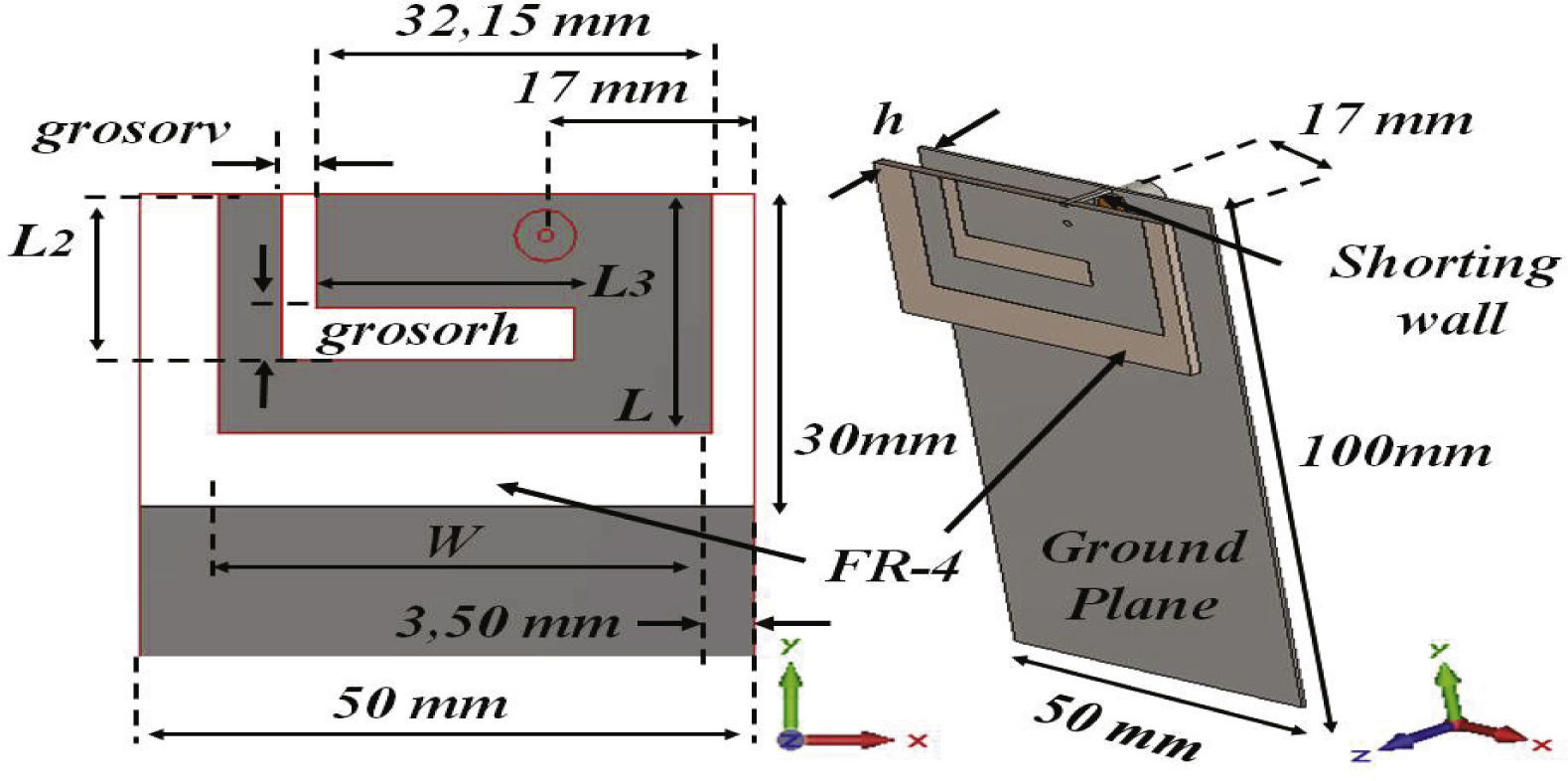
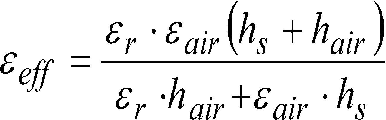
In order to maintain the first resonant frequency (the lower) the dimension of the patch is adjusted. The configuration of the proposed antenna is presented in Figure 2, and it can be seen that there is an air separation between the ground plane and the substrate that hold the patch. For this case an effective dielectric constant is used in the above equations (Kumar & Ray, 2003)
 geometric parameters, b) perspective view.")
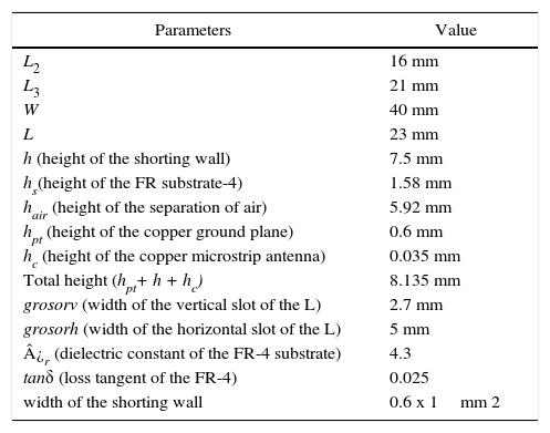
The feeding and the shorting wall are in line in Figure 2, separated by 4mm from the edge where is located the shorting wall to the center of the coaxial probe feed. The parameters of the structure are shown in Table 1.
Geometric parameters of PIFA antenna with L-shaped slot.
| Parameters | Value |
|---|---|
| L2 | 16 mm |
| L3 | 21 mm |
| W | 40 mm |
| L | 23 mm |
| h (height of the shorting wall) | 7.5 mm |
| hs(height of the FR substrate-4) | 1.58 mm |
| hair (height of the separation of air) | 5.92 mm |
| hpt (height of the copper ground plane) | 0.6 mm |
| hc (height of the copper microstrip antenna) | 0.035 mm |
| Total height (hpt+ h + hc) | 8.135 mm |
| grosorv (width of the vertical slot of the L) | 2.7 mm |
| grosorh (width of the horizontal slot of the L) | 5 mm |
| ¿r (dielectric constant of the FR-4 substrate) | 4.3 |
| tanδ (loss tangent of the FR-4) | 0.025 |
| width of the shorting wall | 0.6 x 1mm 2 |
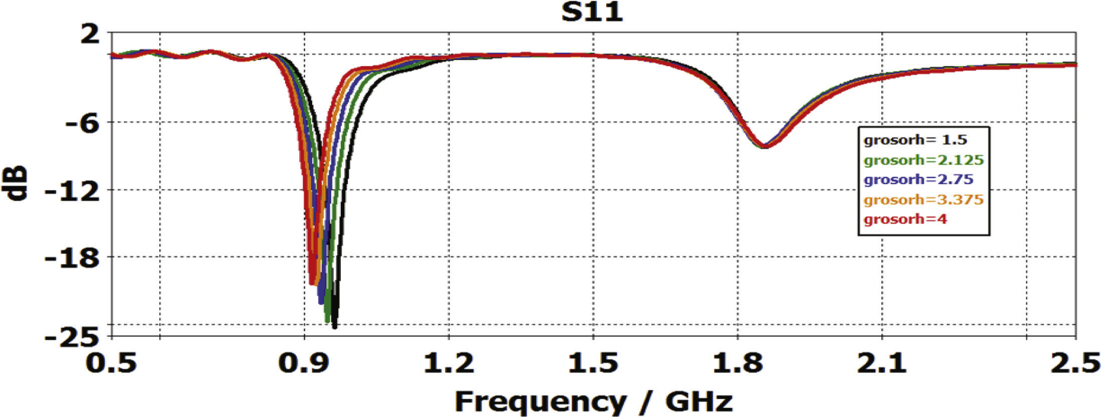
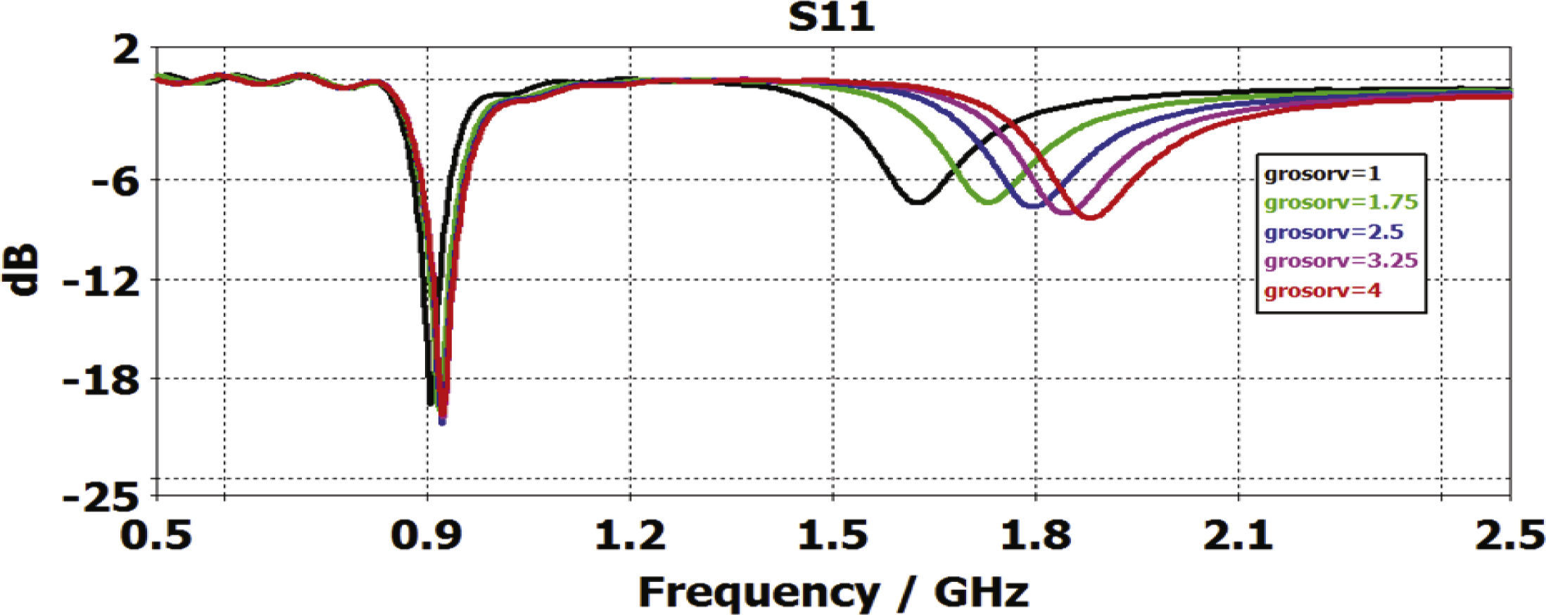
As the slot is a fundamental aspect in the operation of this PIFA antenna, an analysis of the influence of the width of this was carried out to a fine tuning of the structure, dividing the L-shaped slot in two parts: vertical and horizontal. In the first moment, the vertical width slot of the L (grosorv) was kept equal to 3.5mm, and the width of the horizontal slot of the L (grosorh) was varied for 1.5 to 4mm, getting the S11 values of Figure 3.

And in the second moment, was kept grosorh equal to 3.5mm, and was varied grosorv from 1 to 4mm, and were obtained the values of Figure 4.

From Figures 3 and 4, may observe that while the vertical slot allows tuning the upper frequency, the horizontal slot allows tuning the lower frequency. For antennas in mobile devices, the -6dB value of S11 parameter is usually considered as the bandwidth limit (Balanis, 2008).
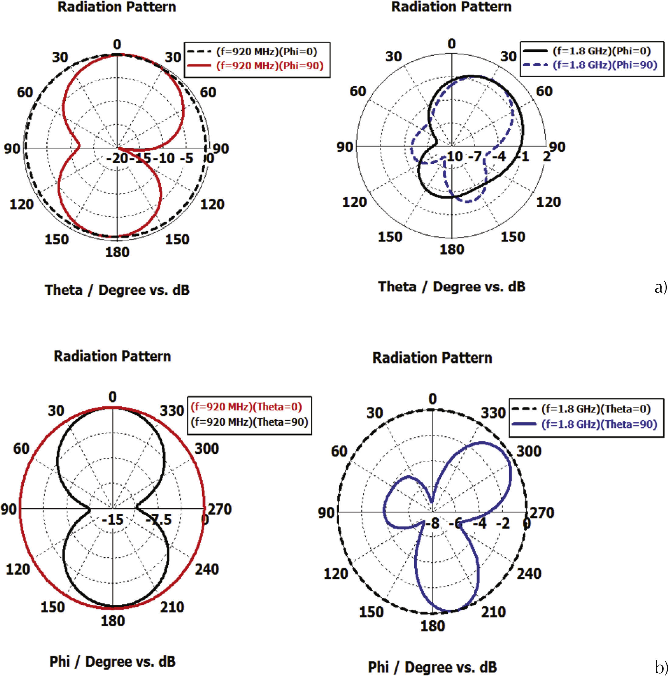
Results of the PIFA of Table 1 are presented in Figures 5, 6, 7 and 8. The S11 parameter is presented in Figure 10.
 920MHz, b) 1800MHz.")
 920MHz, b) 1800MHz.")
 920MHz, b) 1800MHz (the values are given for the main direction).")
 Theta variation, b) Phi variation.")

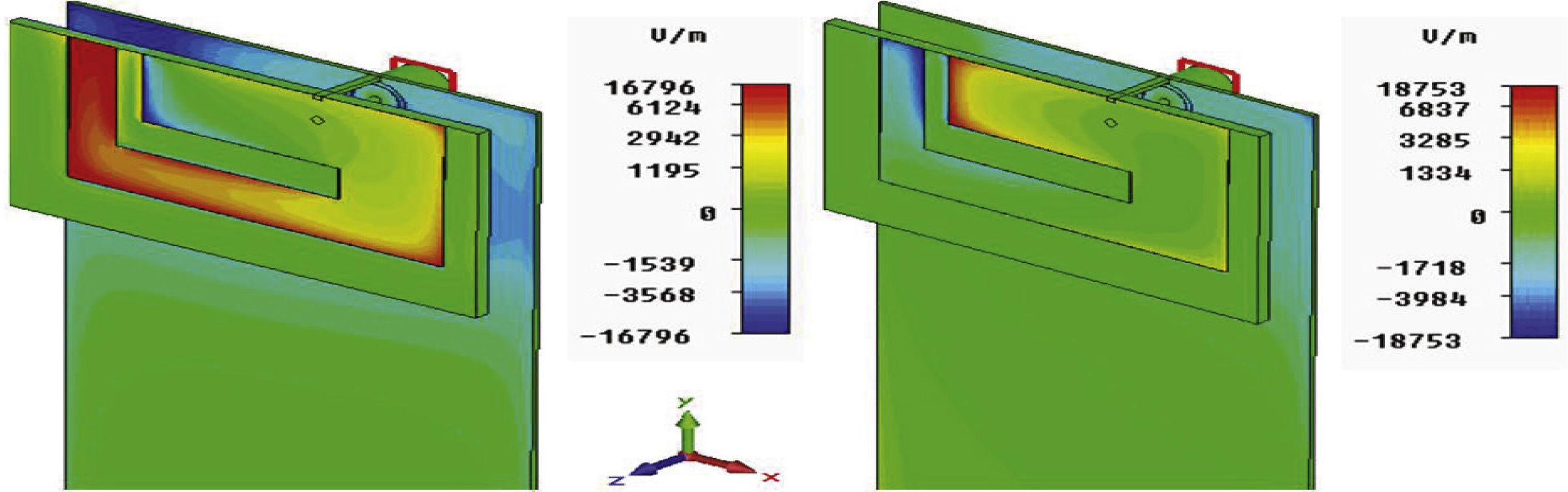
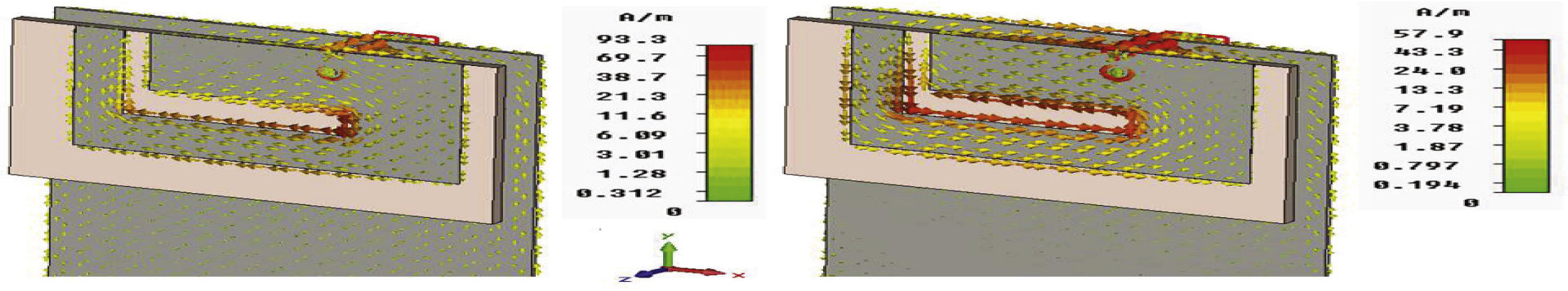
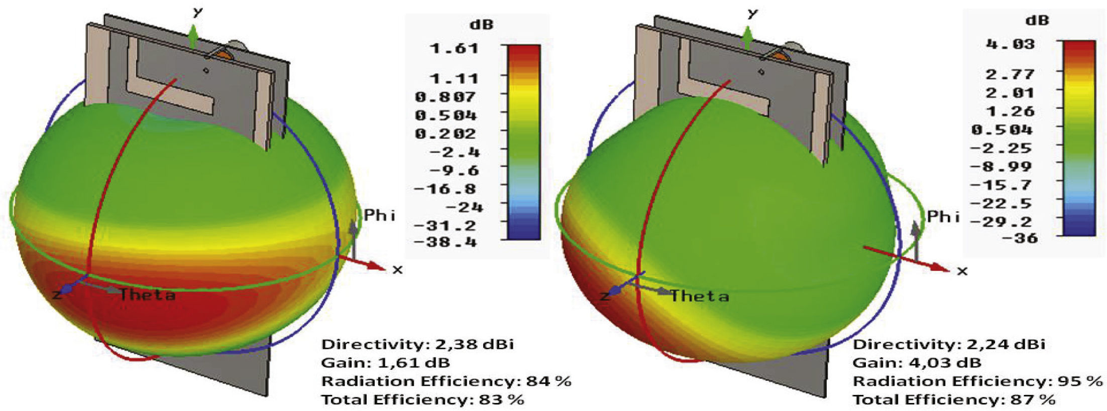
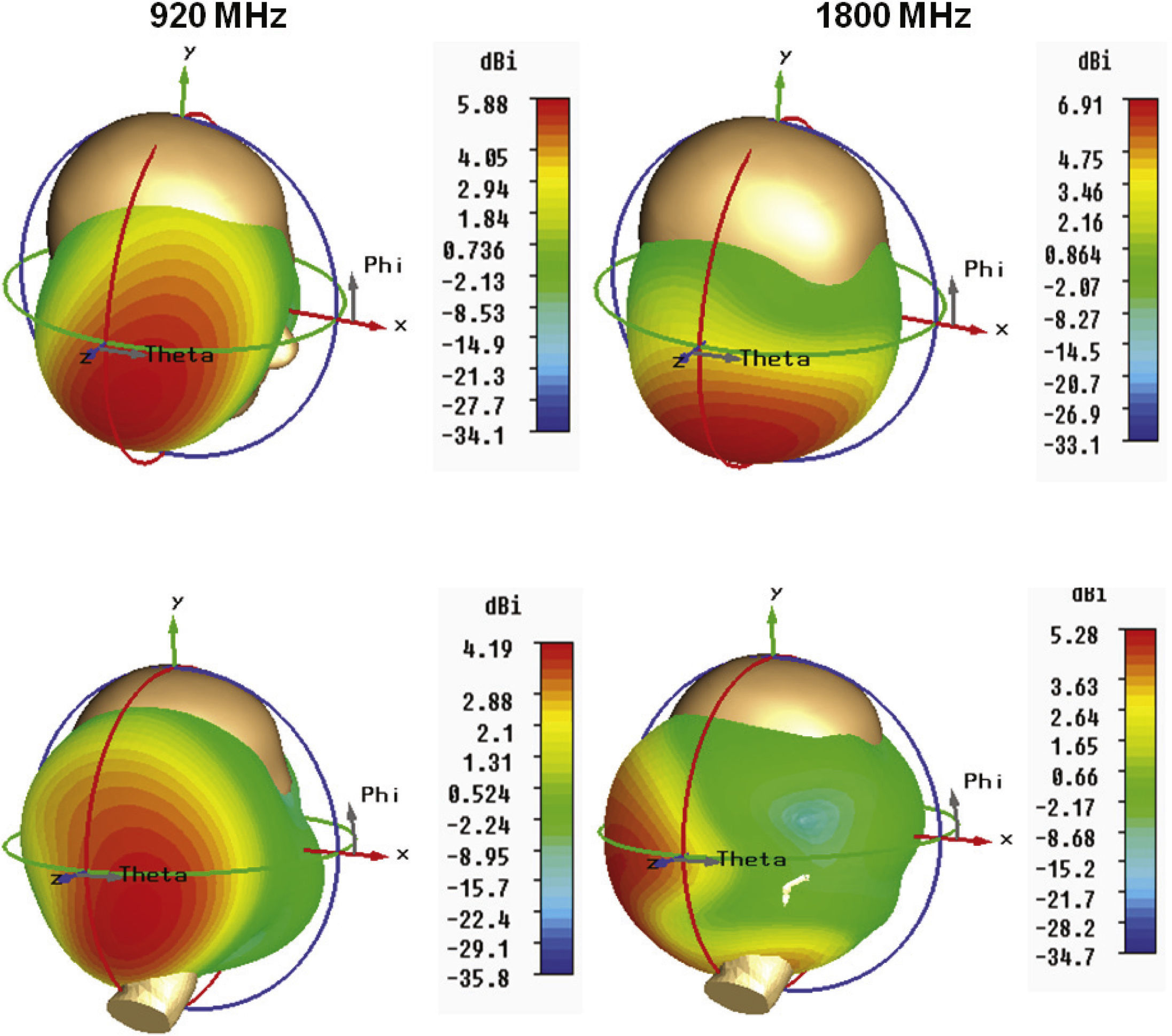
Figure 5 shows the parts where more current intensity flows at each frequency in red color. For the lower frequency of 920MHz, in the outer part circulates the majority of the current, meanwhile for the superior frequency of 1800MHz is in the inner rectangular part. In Figure 6, it is observed the influence of the L-shaped slot in the surface current distribution, where it is more intense the current near the slot for 1800MHz. The radiation pattern obtained with the CST MWS is observed in Figures 7 and 8, in the first figure with a perspective view, and in the second figure in polar coordinates.
Theoretical principles of antenna-user interactionThe electromagnetic field caused for the currents in the surface of the antenna propagates near and through the hands and head of the user that hold the structure. As a result, a polarization of the cells in the human body occurs as a product of the heating in near parts to the radiator. This radiation exposure, if is not regulated, can cause damages to the health of the user. The amount of radiation that can absorb the tissue is evaluated by means of the SAR (Specific Absorption Rate), parameter that can be defined as the power absorbed per volume element of human tissue with certain conductivity (American National Standard, 1999)
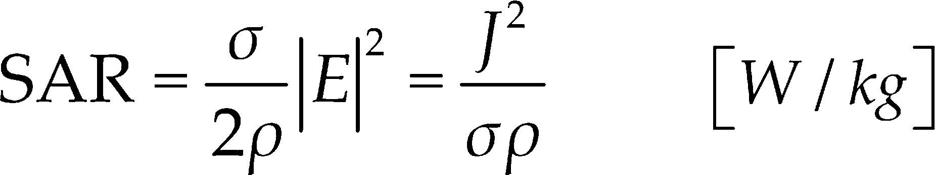
where
σ(S/m) and ρ(kg/m3) = conductivity and the density mass of the tissue respectively
E = total amplitude of the electric field (mean quadratic value)
J = current density vector
Nationals and internationals organizations recommend values for the permissible maximum SAR produced for the antennas in mobile devices. The ANSI/IEEE standard C95.3-1999 (American National Standard, 1999) suggests that in a 1g of tissue mass the maximum SAR must not be higher than 1.6W/kg, and for the whole body must be less than 0.08W/kg. The value of 2W/kg of maximum SAR defined for 10g is normally used in Europe.
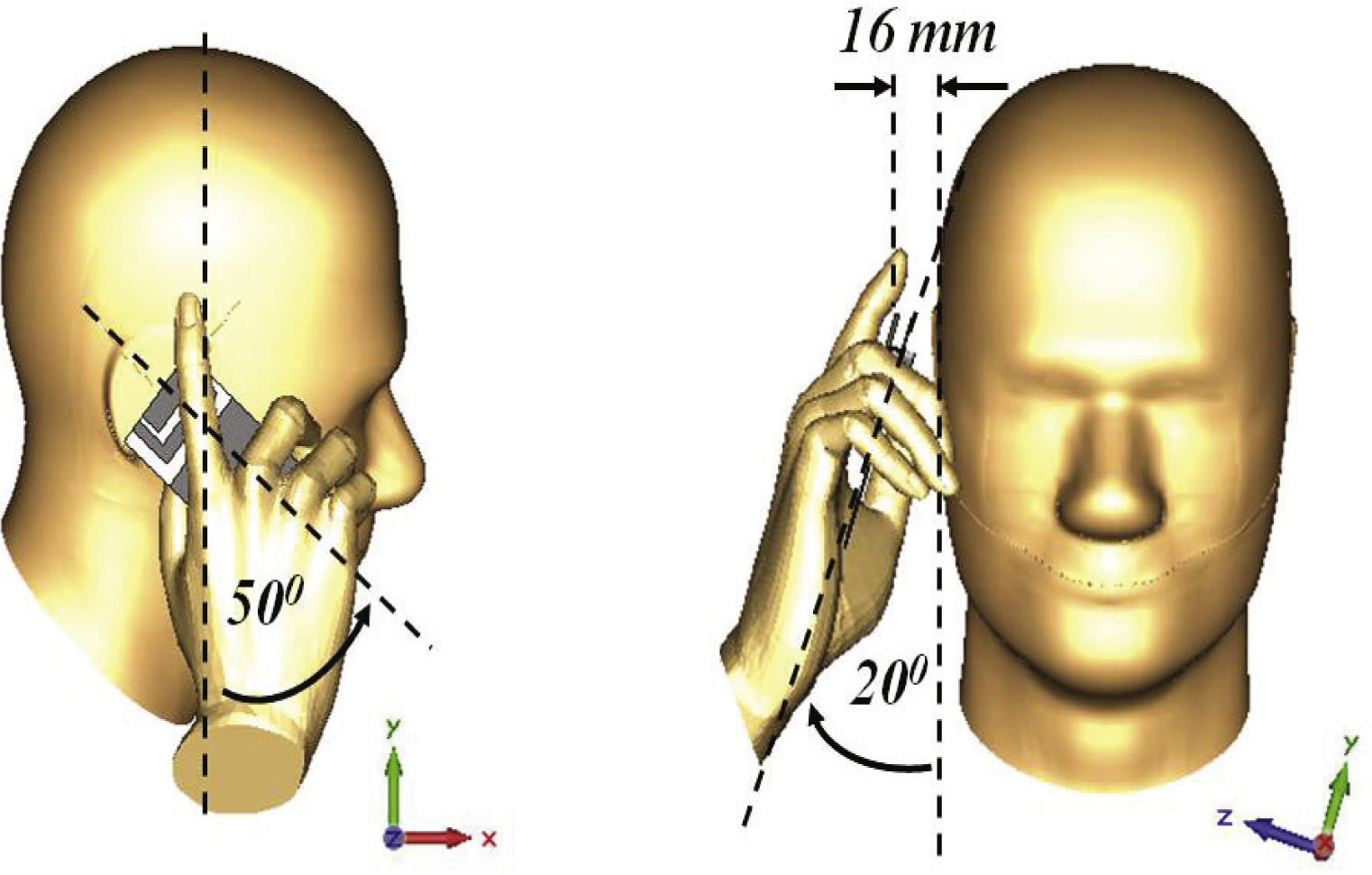
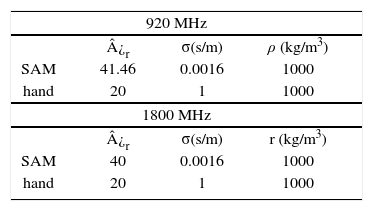
In this work, three simulated experiment were carried out using CST MWS software for SAR evaluation. First, it is evaluated the antenna-head interaction; second, the antenna with a hand model; and finally, the interaction of the hand and head with the antenna. SAM models of hand and head were used. Despite that they are an approximation of the reality, this use is considered appropriate, as it has been presented in several articles (Montaser et al., 2012; Al-Mously & Abousetta, 2012; Liu & Zhao, 2014; Lee & Sung, 2014). The properties of the models are given in Table 2. They are based on the phantom model provided by CST MWS, where an additional average density was added to the hand to evaluate the SAR in it.
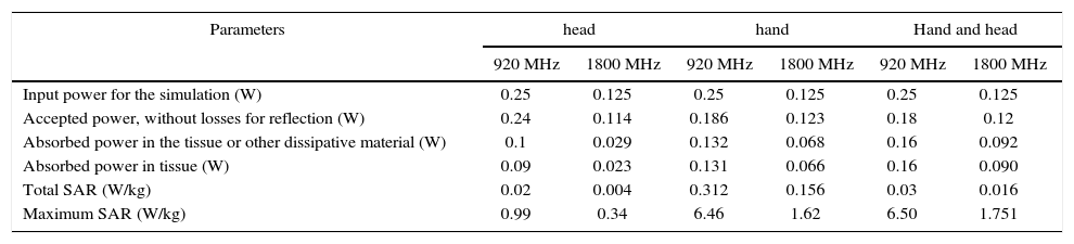
Evaluation results of PIFA near to the hand and head SAM modelThe configuration of the antenna with hand and head models is presented in Figure 9. The SAR is calculated with an output power from de antenna of 24 dBm (0.25W) for the frequency of the GSM 900 band, and a power of 21 dBm (0.125W) for the band of GSM 1800, as was done in (Lee & Sung, 2014). These are common values for mobile devices into these bands and service. The method of averaging volume used is the IEEE C95.3.

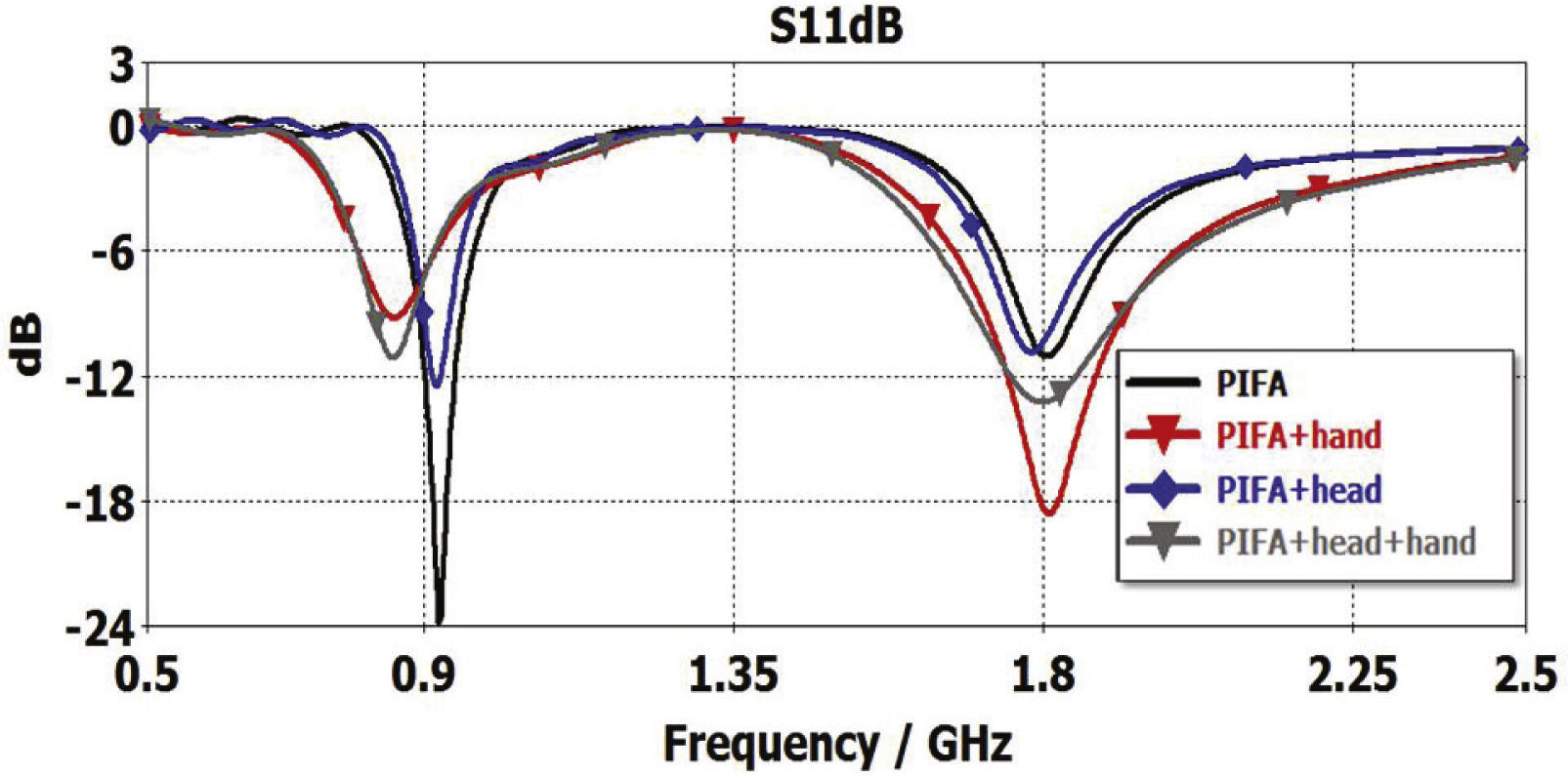
Figure 10 shows the S11 parameter for each configuration: the PIFA antenna isolated and the three simulated experiments.
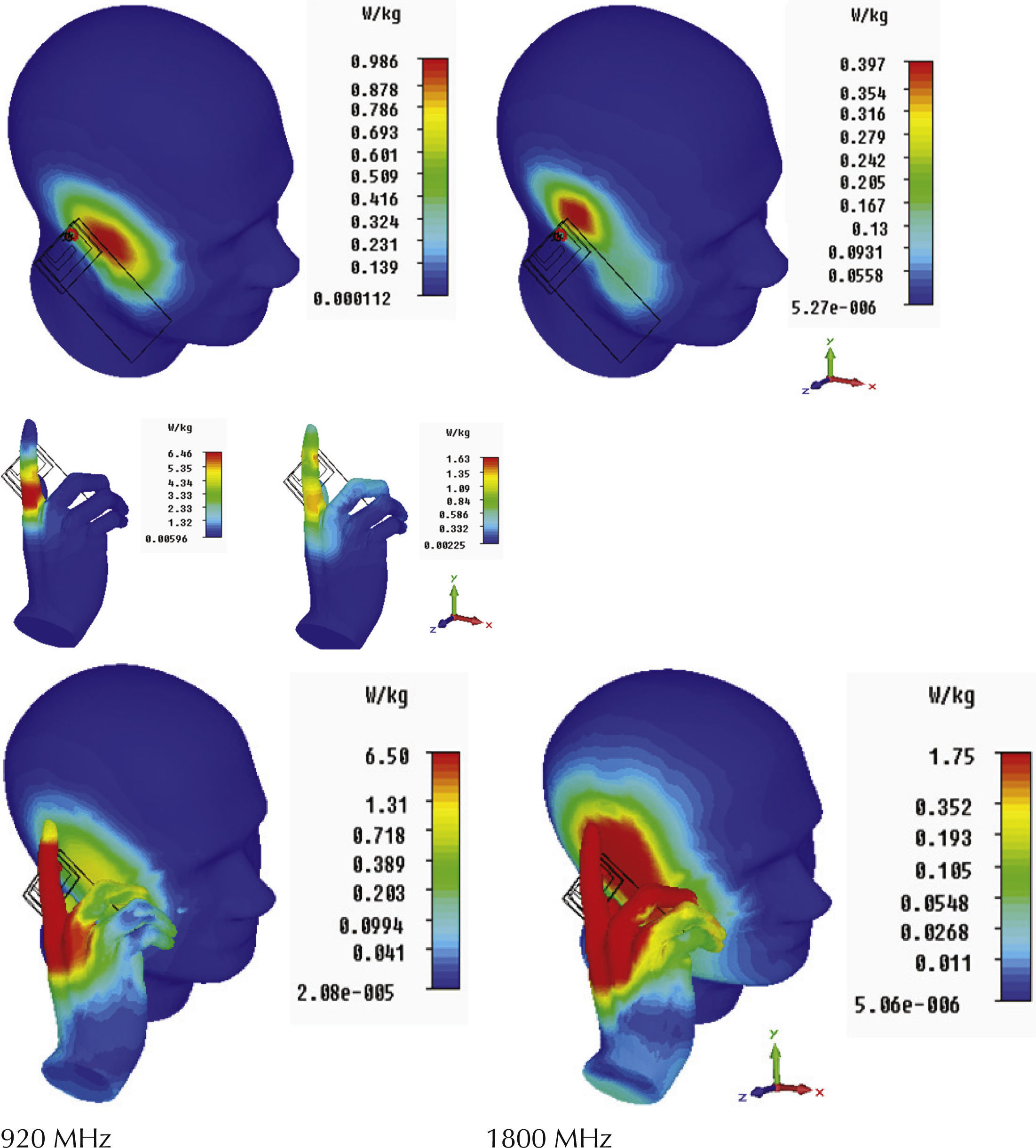
In Figure 11 the SAR distributions are presented. It is notice that the higher amount is concentrated fundamentally in the hand, and in smaller amount in the head. The values of 0.08W/kg (total SAR) and 1.6W/kg (Maximum SAR) are not exceeded for the head model, and total SAR is not exceeded for the hand and head model. The maximum SAR for the hand and head model is high, because it takes into account the maximum value of both elements, which is provided by the hand. The fundamental parameters according to the SAR for each configuration are shown in Table 3. The radiation patterns are observed in Figure 12, and can be seen that the directivity is maximum in opposite direction of the head, which is the most important part of the body to protect from the radiation.
 in the different configurations: PIFA and head model, PIFA and hand model, and PIFA with hand and head models.")
Parameters of SAR for a volume mass of 1g.
| Parameters | head | hand | Hand and head | |||
|---|---|---|---|---|---|---|
| 920 MHz | 1800 MHz | 920 MHz | 1800 MHz | 920 MHz | 1800 MHz | |
| Input power for the simulation (W) | 0.25 | 0.125 | 0.25 | 0.125 | 0.25 | 0.125 |
| Accepted power, without losses for reflection (W) | 0.24 | 0.114 | 0.186 | 0.123 | 0.18 | 0.12 |
| Absorbed power in the tissue or other dissipative material (W) | 0.1 | 0.029 | 0.132 | 0.068 | 0.16 | 0.092 |
| Absorbed power in tissue (W) | 0.09 | 0.023 | 0.131 | 0.066 | 0.16 | 0.090 |
| Total SAR (W/kg) | 0.02 | 0.004 | 0.312 | 0.156 | 0.03 | 0.016 |
| Maximum SAR (W/kg) | 0.99 | 0.34 | 6.46 | 1.62 | 6.50 | 1.751 |
 for the PIFA in interaction with models, a) head only, b) hand and head.")
In this paper the design of a PIFA antenna with an L-shaped slot and it SAR evaluation for three simulated experiment was carried out. The L-shaped slot permits the operation in a secondary frequency band, and the variation of its widths allows tuning the structure for both frequencies. The slot was divided in two parts (vertical and horizontal) for the variation of its width. While the variation of the vertical slot width allows the fine tuning of the upper frequency, the variation of the horizontal slot width allows the fine tuning of the lower frequency.
Comparing the S11 parameter of the PIFA only and interacting with the models, is observed that the hand model has the greater influence in the operation frequencies shift, because the hand introduction cause a major diminution of the lower frequency, product of the model composition and it proximity to the antenna structure. The position and configuration selected for the antenna allows that the radiation is in an opposite direction to the head model. Also, SAR parameters are under the maximum allowable for the standard, making the design suitable for mobile devices. Although the SAM models are considered appropriate for simulations, the effects of the housing and the real properties of tissues must be taken into account for more accurate approximation.
Chicago style citation
ISO 690 citation style
Domingo Pimienta-Del Valle. He received an engineer degree in telecommunication and electronic at the University of Pinar del Río and an M.S. in telecommunications and telematics at the High Polytechnic Institute “José Antonio Echevarría” (CUJAE), in 2010 and 2014 respectively. He is a professor in the Department of Telecommunication and Electronic at the University of Pinar del Río, Cuba. His research interest includes microstrip, fractal, reconfigurable and mobile handset antenna design and microwaves and millimeter wave propagation.
Raidel Lagar-Pérez. He received a licentiate degree in physic and astronomy in 1992, M.S. degrees in sciences of education and in informatics in 2007, and a PhD degree for the University of Pinar del Río, Cuba in 2013. He is an auxiliary full professor in the Department of Telecommunications and Electronic at the University of Pinar del Río. His research interest includes investigations in problems of electromagnetism, radio wave propagation, and photonic optic.