


Welding processes are generally used in almost every industrial segment, but there are some applications that demand special attention to the product obtained, due to the security it must offer against possible failures.
In the present study, the influence of the heat input variation on the weld bead geometry, the austenitic grain size in the HAZ, the microhardness in the HAZ (heat affect zone), and the δ ferrite volumetric fraction using the gas metal arc welding (GMAW) performed with pulsed chain spray transfer, on AISI316L steel plates. The samples had their microstructure characterized by optical microscopy, in their different regions, performing a comparative study of these regions for the different welding conditions. From the variations in the thermal contributions it was demonstrated that the choice of the ideal heat input for a given process has an important effect on the phenomena that occur during welding. The increase of the contribution caused a variation of almost 300% in the austenitic grain size, approximately 100% in the δ ferrite volumetric fraction, and about 240% in the area of the fusion zone (FZ). The temperature distributions of the plates were recorded using a thermal camera in order to monitor the maximum temperatures in each region of the welded joint, the microstructures resulting from the process were later compared with the results of the thermal cycles obtained through numerical simulations. The results showed good agreement and also contributed to the validation of the proposed numerical method, which allowed a better understanding of the thermal history during welding and, consequently, of their effects on the microstructural transformations developed in the AISI 316L steel.
Stainless steels can be defined as ferrous alloys containing Fe as the base element, chromium as the main alloying element, additions of nickel and, in some cases, other alloying elements [1]. The designation of stainless steel corresponds only to Fe–Cr or Fe–Cr–Ni alloys containing more than 10–12% chromium [2].
The chemical composition of these steels, together with the thermomechanical processing to which it is subjected, results in different microstructures at room temperature, so that through these microstructures resulting from the process stainless steels can be classified into four classes: ferritic stainless steels 400 series (200 series and 300, including superaustenitic) and some others, such as duplex stainless steels and precipitation curable steels [3].
Austenitic stainless steels contain between 6 and 26% Ni, 16 and 30% Cr and less than 0.30% carbon, with a total alloy content of at least 26% [2]. Its characteristics are low flow limit, high ductility, high coefficient of thermal expansion and mechanical resistance, low thermal diffusivity and are among the stainless, which have better weldability and general resistance to corrosion. However, they may suffer from pit corrosion in environments containing chlorides.
Considering the purpose of the present study, austenitic stainless steels can be applied because they have higher hardness and ductility than most other steels and are kept at very low temperatures. Therefore, these steels are considered for using in welded structures to be used at the helium condensation temperature (4K or −269°C), such as the magnet structure in experimental nuclear fusion reactors.
However, when subjected to a severe thermal cycle, these properties can be altered and even lost, compromising the application of steel. For these reasons there are a constant need to conduct research and applied studies and continuously collaborating to increase the theoretical and experimental knowledge of the issue addressed in the present study.
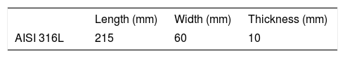
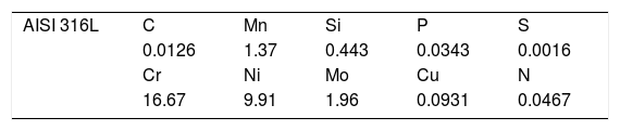
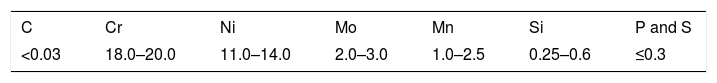
2Experimental work2.1Materials and methodsThe materials used in the experimental welding process of the present work were three sheets of austenitic stainless steel AISI 316L. Tables 1 and 2 show, respectively, the dimensions of the plates analyzed and the chemical analysis of the steel.
It is important to mention that the materials, after the manufacturing process, were subjected to adequate solubilization heat treatment in order to dissolve formed precipitates during the working and shaping processes. However, no information is available from suppliers regarding temperatures and solubilization times. Therefore in this study we carried out as received analysis for understanding the initial microstructure and proprieties.
2.2Welding consumablesThe addition wire used was ER316L, which is an extra low carbon electrode, which is know as avoiding the sensitization phenomenon, type CrNiMo 19/12/3 for welding of austenitic stainless steels type AISI 316L. Table 3 shows the chemical composition of the wire.
The welding of all plates was performed in a single pass and with deposition of the addition material, forming a bead with a mean extension of 160mm for AISI 316L along the length of the plates, as shown in Fig. 1.
2.3Welding
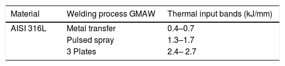
Considering as main objective of this study the microstructural analysis and comparison resulting from the GMAW welding process with pulsed metal transfer for the same heat input range and for the same steel, the welding of the materials was carried out following the ranges shown in Table 4.
The heat input ranges presented in Table 4 were chosen in order to study a lower limit than that technological recommendation for the welding of these materials (0.4–0.7kJ/mm), an upper limit to the recommended one (1.3–1.7kJ/mm) and a value well above the recommended range (2.4–2.7kJ/mm). In addition, the parameters used in the welding of the three plates of the AISI 316L were all the same, the variation of the contribution being obtained only by the variation of the welding speed. There are three samples, welded with GMAW process with pulsed metal transfer, being AISI 316L steel one with low, one with intermediate and one with high heats input. In this way, comparisons can be established among thermal welding cycles, cooling rates and final obtained microstructures, Vickers microhardness profiles, melt zone dimensions, delta ferrite quantification in the heat affected zone and melt zone, and grain size in the heat affected zone (HAZ), parameters and technological aspects that qualifies the weldment procedures and quadrate the safety of the structures.
In addition to these parameters, were maintained constant the following conditions established initially using a synergic and controlled equipment:
- •
Stick-out: has been manually adjusted, having a fixed value of 17mm.
- •
Gas flow: Adjusted through the cylinder valve, having a fixed value of 17l/min.
- •
Welding speed: it is one of the main parameters, because it directly influences the value of the heat input. The welding speed was adjusted by the speed of the car by adjusting the frequency of the car's motor in the frequency inverter.
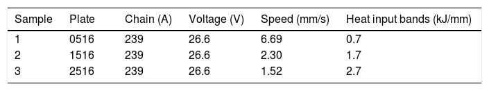
The following parameters are considered fixed for all weldment procedures: Stick-out equal to 17mm, gas flow equal to 17l/min, protection gas composed of 98% argon and 2% oxygen and addition wire ER316L with a diameter of 1.2mm. Table 5 presents an overview of the other welding parameters used in the welding of the three plates, referring to AISI 316L. The nomenclature used is according to the range of the heat input practiced, the type of material. In this way, the first two numbers indicate the range of the heat input practiced, and the second two numbers define the type of material. Thus, for the plate named 2516 the range of the heat input is between 2.4 and 2.7kJ/mm.
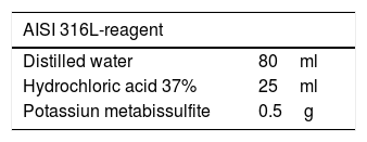
2.4Microstructural characterizationAfter cutting and preparation of the sample as received, for comparison purposes it was polished using silicon carbide grades of the following granulometries: 100, 220, 320, 400, 600, 800, 1200, 2500 and 4000 mesh. Subsequently, the mechanical polishing of the samples was carried out using as an abrasive diamond paste of 1μm granulometry and then the sample was attacked by immersion with the reagent Beraha, with composition according to Table 6.
After the welding process, a sample of each plate was taken for microstructural characterization (phase analysis, measurement of austenitic grain size, quantification of δ ferrite in the heat affected zone and in the melt zone), quantification using Image Pro Plus 4.0 software, dimensioning of the molten zone and Vickers Microhardness measurement in the different zones (heat affected zone, melt zone and base metal).
2.5Numerical methodologyThe computational modeling applied in this evaluation aims to simulate the effects of the variation of the welding Heat input on the thermal cycle of the welded material (AISI 316L). The model is capable of predicting the transient temperature distribution during welding. Thus, it predicts temperature and times that the material is exposed to thermal cycles, which resulted in microstructural and mechanical properties changes. In this way, the thermal cycles obtained by means of this model is later compared to results of the microstructures obtained experimentally, analyzing the theoretical effects of cooling rates and dynamic developments during the experiment. The software used for modeling was developed by the authors is termed Welder-3D. The software is based on the numerical solution of the heat equation coupled with dynamic development of local thermophysical properties [4]. The model equations were programmed in Visual FORTRAN 95 running on windows platform.
In the computational modeling process, heat transfer phenomena (radiation, convection and conduction) coupled to mass transfer phenomena (melting and solidification) are considered. In order to simplify and make feasible the elaboration of the model for computational simulation, some considerations were made [4–9]:
- •
the loss of heat on the surface of the plate occurs by convection and radiation;
- •
torch speed is constant’
- •
deposition of only one weld bead;
- •
welding electrode running through the plate;
- •
the distance between electrode and plate is constant.
This model is based on the resolution of the differential equation of energy conservation (Eq. [1]), the temperature (T) being the dependent variable, accordingly:
where:
ρ: density of steel (kg/m3);
cp: specific heat (J/(kgK));
k: thermal conductivity (W/(mK));
u→: vector speed (m/s);
T: temperature (K).
The variable, S is the heat source, which corresponds to all input sources or heat loss in the process (energy/heat added in welding, phase transformation, melting and solidification), which in this work will be given by the double-ellipsoid model proposed by Goldak et al. [10].
The Goldak model (Eqs. (2) and (3)) is also known as double ellipsoid, since the heat distribution is modeled (in the volume) as two ellipses, one ahead of the torch heat source and the other behind, as shown in Fig. 2. To model the welding process and to predict the temperature in the plate, the same parameters of the experimental process were considered. In addition, some additional considerations were made in order to make feasible the computational simulation: loss of heat on the surface of the plate by convection and radiation, no diffusion of chemical elements between the added metal and the base metal and chemical composition of the metal. The calculation domain is assumed the plate and moving torch with heat input given by the measured current and voltage.

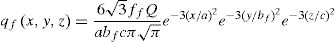
In this work by Goldak et al. [10], the heat of the welding arc in motion is applied as a volumetric heat source with a double ellipsoid distribution following Eqs. (2) and (3): The front half of the heat source is defined by Eq. [2][11]:
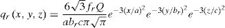
The back half to the heat source is defined by Eq. [3]:
At where:
- •
ff and fr: represent respectively the fractions of heat deposited in the front and rear halves of the heat source;
- •
Q: represents the magnitude of the welding energy per unit time (Q=ηVI) where η is the process efficiency, V is the voltage in volts and I is the current in Ampere;
- •
v is the welding speed (m/s);
- •
t is the welding time (s);
- •
af, ar, b and c: are parameters that are related to the characteristics of the welding arc, defining the size and shape of the ellipse and, consequently, the volumetric distribution of heat source.
In the welding process, the loss of heat on the surface of the plate occurs by convection and radiation, which considers the two effects, follows Eq. [4]:
where: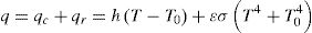
T0 (environment temperature)=25°C;
ɛ (emissivity)=0.682;
σ (constant of Stefan–Boltzman)=5.67×10⁻⁸W/(m2K4);
h (convection coefficient)=15W/(m2K).
The initial condition adopted assumes that the temperature of the domain is same as the environment equal to 25°C.
The solution to the differential equation of energy conservation (Eq. [2]) can be obtained by applying the finite volume technique to a generalized coordinate system. After integration in time and space and through algebraic arrangements, the equation of energy conservation is obtained in the discretized form (Eq. [5]).

The terms of Eq. [5] represent the flux of energy thought the discretized control volume faces. The coefficients of Eq. [5] can be obtained using the power law scheme, found in the literature [12]. The solution of the discretized equation is then obtained using the line-by-line method described by Patankar combined with the tri-diagonal matrix solution algorithm. This sequence of operations were implemented and used previously [4–9].
3Results and discussion3.1Material microstructure in the received stateFig. 3 shows the micrograph of the base metal (BM) of this study, AISI 316L steel. The microstructure of this steel consists of recrystallized austenite grains, with the presence of annealing blades that are characteristic of this material. However, heterogeneity of the matrix was observed, evidenced by the different grain sizes, which affect the thermophysical properties [8]. In addition, the presence of small bands of δ ferrite [13] can be observed.

The average value of the Vickers microhardness of AISI 316L steel in the state as received with a 95% confidence interval is 170±3.0HV.
3.2HAZ microstructure of welded jointsIn this topic we will discuss the results concerning the microstructure, austenitic grain size, δ ferrite volumetric fraction and Vickers microhardness exhibited by welded joints of AISI 316L steel.
Fig. 4 shows the binary phase transformation diagram of the 316L steel, the straight line segment AB highlighted in red. In this region during the cooling process of the steel occurs the formation of ferrite δ, because it is a diffusional reaction the formation of the ferrite depends on the time, so the longer the alloy remains in this field, the greater the fraction of ferrite δ formed.
![Pseudo-binary diagram of the Fe [Cr–Ni]eq system presenting the green line referring to the value of [Cr/Ni]eq for AISI 316L [9].](https://static.elsevier.es/multimedia/26036363/00000030000000S1/v3_201903020710/S2603636318300575/v3_201903020710/en/main.assets/gr4.jpeg?xkr=ue/ImdikoIMrsJoerZ+w997EogCnBdOOD93cPFbanNckJTby9XNwsiuXRctoRgJ29Slg9gZMo4/N5gs0UDEPONQ2eI53z6sUaK2dcXFOcAT3xOWj1dsvd60hqyWa9ilVhbepRNtZ+eQ3141AA8Kt8oPznYS+SiWf7Zx9aCWNMqlajMVB6sXl1Q1/ipkIWVkF+zCsKW3xvYmJ0dwmBMp1Z+wJ5v7PUvnYLmuQIAmT/gmhjdvmDr+wWOYLH6btGZTfiVdEk+vYuHKSkRcl5iU710vfSde4bJBNEzSOHPooZ3VZO+rtIqMHFjSmpUZRFqyd "Pseudo-binary diagram of the Fe [Cr–Ni]eq system presenting the green line referring to the value of [Cr/Ni]eq for AISI 316L [9].")
Pseudo-binary diagram of the Fe [Cr–Ni]eq system presenting the green line referring to the value of [Cr/Ni]eq for AISI 316L [9].
According to Ronqueti [14], the heat affected zones, HAZ of AISI 316L austenitic stainless steels contains amounts of ferrite δ and austenitic grains [14]. In addition, the transition zone (ZT), between the molten zone (MZ) and HAZ, is mainly differentiated by the δ ferrite morphology [14,15].
The curves represent the simulated thermal cycle in the region indicated by the number at each curve. Figs. 5–7 show respectively the microstructure of the BM/HAZ/MZ interfaces, the thermal cycle calculated by the numerical model, and the thermal image obtained after the welding process, for the welded joint with heat input of 0.5kJ/mm.


Figs. 8–10 show respectively the microstructure of the interfaces BM/HAZ/MZ, The thermal cycle calculated by the numerical model, and the thermal image obtained shortly after the welding process, for the welded joint with heat input of 1.5kJ/mm.
, melt zone (MZ) and metal of base (MB) for heat input of 1.5kJ/mm. Image obtained with 200× in optical microscope (OM), chemical attack of Beraha reagent.")


Figs. 10–12 show respectively the microstructure of the BM/HAZ/MZ interfaces, the thermal cycle calculated by the numerical model, and the thermal image obtained shortly after the welding process, for the welded joint with heat input of 2.5kJ/mm (Fig. 13).


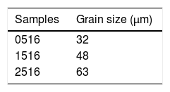
Table 7 shows the values of the austenitic grain size that the HAZ of the samples of the welded joints of the AISI 316L presented. When comparing the austenitic grain size presented by the BM (22.0±4.1μm) and the austenitic grain size presented in the HAZ, it is possible to observe that all the samples evidenced the austenitic grain growth in the HAZ, as Silva also stated in 2009 [16].
Fig. 14 shows a plot with average grain size in HAZ as a function of the heat input.

As expected due to the thermal cycle suffered by the region the austenitic grains suffered an increase when compared to the material as received.
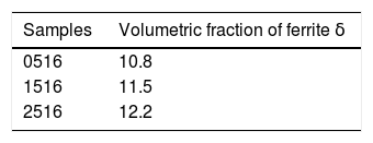
3.4Quantification of delta ferrite in HAZTable 8 shows a quantitative analysis of the presence of delta ferrite in the HAZ region, so that the connection between the increase of the thermal contribution and the presence of this phase in the HAZ region can be correlated.
Fig. 15 shows a graph with the behavior of the quantification of the ferrite delta HAZ as a function of the heat input.

As Kumar observed in 2011 [17], an increase in the amount of δ ferrite was expected due to the increase of the heat input, the cooling rate decreased, causing the material to pass more slowly through the ferrite δ formation region, then the volumetric fraction increased when compared to that of the material as received.
3.5Welded joints MZ microstructureFigs. 16 and 17 shows the microstructure of weld metal welded with heat input of 0.5kJ/mm and the calculated thermal cycle that was submitted respectively. The tangent line to the cooling curve indicates the calculated cooling rate of the microstructure after the welding process.


Figs. 18 and 19 show the weld metal weld metal microstructure with heat input of 2.5kJ/mm and the calculated thermal cycle, which was subjected respectively. The tangent line to the cooling curve indicates the calculated cooling rate of the microstructure after the welding process.


It can be seen that the line of the cooling rate indicated in Fig. 17 shows a steeper slope than the line indicated in Fig. 19. This is due to the higher heat input in Fig. 18, which provides more energy for welded joint resulting in a Temperature, so its cooling rate is lower.
The microstructural characterization and quantification indicated that the lower cooling rate resulted in thinner dendrites with smaller dendritic spacing (Fig. 16), while the higher cooling rate provided dendrites with larger spacings (Fig. 18).
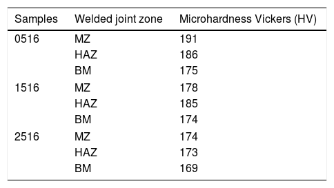
3.6Vickers MicrohardnessAs previously mentioned, the analysis of the Vickers microhardness profile of the welded joint is of fundamental importance when it is desired to evaluate the characteristics of the welded region, since this property is directly related to phenomena of phase and microstructural transformations due to the different thermal cycles developed. Table 9 shows the mean MZ, HAZ and BM Vickers Microhardness values of all AISI 316L plates.
Considering that the average Vickers microhardness of the AISI 316L steel in the state as received is 170±3.0HV, it can be seen that the Vickers microhardness values for the different zones (MZ and HAZ) and base metal (BM) Did not show significant variations after the welding process (considering the Vickers scale ranging from 100HV to approximately 900HV). Thus, this result can be explained as a result of the measurements made in the austenitic matrix, where the thickness of the δ ferrite dendrites is very thin, making it difficult to measure the Vickers microhardness only at this stage. A similar result was obtained by Pessanha [18] in the study of welded austenitic stainless steel.
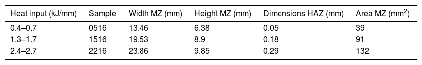
3.7Dimensions of the MZ and HAZIn order to evaluate the influence of the increase of the heat input used in geometry and weld bead dimensions, with the help of the Geogebra and Profileometer software, the regions of the cross sections of the weld beads were designed for the three heat inputs used In welding the AISI 316L, as shown in Fig. 20 and Table 10.

Fig. 21 shows a graph with the behavior of the area of the weld metal as a function of the heat input.

As can be seen in Table 10 and in the graph of Fig. 20, when the heat input is increased the area of the weld metal tends to increase. This is due to the increased heat supplied to the weld joint, so the amount of melt material in the joint is higher resulting in an increase in the area of the weld metal.
4ConclusionsThe increase in the heat input provokes an increase in the dimensions of the fusion area, increase of δ ferrite volumetric fraction and the austenitic grain size in the HAZ. The δ ferrite morphology revealed in the HAZ was classified as vermicular and the presence of unwanted precipitates or intermetallic phases was not observed in the welded joint. The values of Vickers microhardness measured in the different zones showed no significant variations. The contribution of 2.5kJ/mm showed the highest volumetric fraction of ferrite δ, which together with the excessive growth of the austenitic grain size in the HAZ is expected to deteriorates the properties of this region. The heat inputs of 0.5 and 1.5kJ/mm provided the best combined results, with lower δ ferrite volume fractions in the HAZ, as well as MZ. Furthermore, the dimensions and areas of the zones indicated that the welded joints are suitable for these heat inputs.