


Suplement “Update and good practice in the contrast media uses”
More infoSpectral CT acquires images with the emission or detection of two separate energy spectra. This enables material decomposition due to the photoelectric effect (prevalent in low-energy photons) and Compton scattering (prevalent in high-energy photons).
Iodine and other materials with high atomic numbers appear more hyperdense on low-energy monoenergetic images because of the direct relation between the photoelectric effect and the Z value.
Given the way iodine behaves on spectral maps, radiologists can optimise the use of contrast media in these CTs, thus allowing lower doses of radiation and lower volumes of contrast media while achieving the same CT values and even enabling lower contrast flow rates, which is especially helpful in patients with poor vascular access. Moreover, in suboptimal diagnostic cases caused by poor contrast opacification, the resolution can be improved, thus avoiding the need to repeat the study.
La TC espectral adquiere imágenes con dos espectros energéticos diferentes, ya sea mediante emisión o detección. Esto permite diferenciar materiales basándose en el análisis del efecto fotoeléctrico de cada material (que predomina en los fotones de baja energía) y del efecto Compton (predominante en los fotones de alta energía).
El yodo y otros materiales con número atómico alto, se visualizan con mayor densidad en los mapas monoenergéticos a bajas energías, debido a la influencia del efecto fotoeléctrico, que tiene una relación directa con el valor Z.
Debido al comportamiento del yodo en los mapas espectrales, el radiólogo puede optimizar el uso del contraste yodado en estos equipos. Esto permite adquirir imágenes con menor dosis de radiación y menor cantidad de contraste yodado para obtener los mismos valores de la TC, e incluso reducir el flujo de administración de contraste, especialmente útil en pacientes con mal acceso venoso. Además, en los estudios subóptimos por la mala opacificación del contraste, tiene la capacidad de mejorar la resolución y evitar repetir estudios.
Before delving into the particularities of iodinated contrast in dual-energy, spectral or multi-energy computed tomography (CT), we will explain what these systems are and how they differ from single-energy CT.1
Conventional CT uses a single x-ray energy spectrum to differentiate between materials according to their different attenuations, expressed in Hounsfield units (HU).2 However, it is possible that two different structures present the same attenuation coefficient at a certain energy, limiting the potential to differentiate between them.
Multi-energy CT has thus been developed on the principle that each material behaves differently at different energies.3,4 Dual-energy uses two x-ray energy spectra, one at low energy and the other at high energy. The way the datasets are acquired varies according to each commercial manufacturer and may be based on photon emission or detection.5
Thus, dual-energy CT can differentiate between materials by analysing the photoelectric effect (predominant in low-energy photons) and Compton scattering (predominant in high-energy photons) of each material.6 While Compton scattering is influenced by a material’s electronic density, the photoelectric effect is directly proportional to the atomic number of the tissue (Z) (Fig. 1).
, presents a higher photoelectric effect at low energies.")
Each system offers various post-processing techniques including virtual monoenergetic images (VMIs) and material decomposition images (which map or remove iodinated contrast, uric acid etc.).4,7
VMI simulate the attenuation of a single energy spectrum image within the range of 35−200 keV. An attenuation value of 70 keV is the equivalent of a conventional CT performed at 120 kVp.8 The most relevant maps for iodine—and therefore for iodinated contrasts—are low-energy (40–50 keV) VMI maps. It should be remembered that in these images, iodine has higher densities due to the influence of the photoelectric effect which is directly related to the Z value (Fig. 2), making them highly useful in vascular studies as well as in the detection and delineation of tumours.9,10 The behaviour of iodine in these maps means that radiologists can optimise the use of contrast media in these systems (Fig. 3).
 simulate the result of the scan if it had been performed at a single energy. Note how the VMI at 40 keV enhances the iodine density due to the photoelectric effect.")
 Conventional axial CT images in venous phase. (C and D) Low-energy monoenergetic images (45 keV), showing filling defects in the pulmonary arteries compatible with acute pulmonary thromboembolism (arrows), which are barely visible on conventional CT (arrows).")
Male, aged 80, with stage IV adenocarcinoma of the pancreas. CT reassessment. (A and B) Conventional axial CT images in venous phase. (C and D) Low-energy monoenergetic images (45 keV), showing filling defects in the pulmonary arteries compatible with acute pulmonary thromboembolism (arrows), which are barely visible on conventional CT (arrows).
The aim of this article is to describe the particular behaviour of iodine in multi-energy systems, and to show the benefits of using multi-energy devices to optimise the use of iodinated contrast.
Optimisation of iodinated contrastsVarious factors have to be taken into account when we speak of optimising iodinated contrasts in spectral systems. These include those concerning the patient, those dependent on the CT and finally, those specific to the intravenous contrast medium (ICM11 (Fig. 4). This article will only focus on those factors related to the ICM.

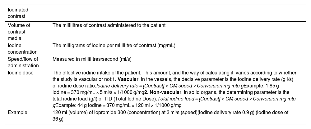
We need to be aware of several concepts regarding the contrasts before we can speak of their optimisation. Specific concepts are defined in Table 1.
Definition of concepts of iodinated contrast media.
| Iodinated contrast | |
|---|---|
| Volume of contrast media | The millilitres of contrast administered to the patient |
| Iodine concentration | The milligrams of iodine per millilitre of contrast (mg/mL) |
| Speed/flow of administration | Measured in millilitres/second (ml/s) |
| Iodine dose | The effective iodine intake of the patient. This amount, and the way of calculating it, varies according to whether the study is vascular or not:1. Vascular. In the vessels, the decisive parameter is the iodine delivery rate (g l/s) or iodine dose ratio.Iodine delivery rate = [Contrast] × CM speed × Conversion mg into gExample: 1.85 g iodine = 370 mg/mL × 5 ml/s × 1/1000 g/mg2. Non-vascular. In solid organs, the determining parameter is the total iodine load (g/l) or TID (Total Iodine Dose).Total iodine load = [Contrast] × CM speed × Conversion mg into gExample: 44 g iodine = 370 mg/mL × 120 ml × 1/1000 g/mg |
| Example | 120 ml (volume) of iopromide 300 (concentration) at 3 ml/s (speed)(iodine delivery rate 0.9 g) (iodine dose of 36 g) |
One of the advantages of using low-energy monoenergetic images is that the volume of iodinated contrast can be reduced, in comparison with that used in conventional CT.12 While there is still some debate on the issue, it can be especially useful in patients with renal function deterioration.13,14
Previous studies have validated the use of low-keV VMIs in studies performed with lower volumes of contrast in CT angiographies of various anatomical structures: head and neck, heart and lungs, aorta, abdomen and extremities.10,15–17
There is less evidence on this approach for the study of solid organs or hollow viscera, but it has been validated by some authors, particularly in liver analysis.18–20
We need to bear in mind that contrast volume reduction protocols might vary depending on the spectral CT system so that diagnostic findings remain accurate. Therefore, it is important to know what equipment is available when determining how to optimise and use iodine values in the different maps.21,22
Shuman et al.23 demonstrated that it is possible to reduce the iodine volume by 50% in CT angiography studies of the aorta using rapid kV switching systems and VMI maps at 50 keV, and still attain a contrast-noise ratio (CNR) comparable to that of standard-dose studies with conventional CT systems at 120 kVp. Tsang et al.24 also found that a 50% volume reduction is possible using VMI at 50 keV with dual-layer detector spectral scanning compared with polychromatic imaging at 120 kVp.
It is important to remember that a significant decrease to the energy level in VMIs increases the image noise, but thanks to artificial intelligence methods, such as iterative reconstruction, it is possible to improve the CNR.25 When we use iterative reconstruction to reduce noise, it does not change the iodine density values of the study.26 In practice, the optimal CNR for iodine varies depending on the spectral equipment, and occurs in VMIs at 40–70 keV.27,28 The latest generation of spectral CT, such as photon-counting CT, mitigates this problem because its innovative technology significantly reduces image noise and improves CNR.29
It should be noted that the radiation dose inversely affects the attenuation of iodinated contrast. According to Yu et al.,30 iodine attenuation at 80 kV is about 70% higher than at 120 kV. Nevertheless, the reduced radiation dose does not generate statistically significant differences in the correct quantification of iodine or the attenuation values in VMIs, unless the doses are minimal (<10 mGy).31
For thin patients and some angiographic studies, the radiation dose can be reduced by 20–50%.32 However, for patients with a higher body mass index or for other studies, image quality may be affected if radiation is decreased too much.33
Given that dose reduction in multi-energy systems is not an easy task and requires time to adjust and learn, several commercial manufacturers have developed strategies for the automatic selection of the optimal radiation dose, which take into account factors including the patient’s weight, contrast volume and image noise.
Vasconcelos et al.34 concluded that it is possible to reduce the contrast volume by more than 60% by using an automated method with a protocol that accommodates for both the patient’s weight and the CT radiation dose. Nakayama et al.35 demonstrated that by reducing the radiation dose to 90 kV and the contrast volume to 40 ml in CT angiographies of the aorta, there was an improvement in aortic density with attenuation values of more than 200 HU in 89.5% of patients, compared to those of the standard protocol of 120 kV and 100 ml of iodinated contrast.
On the other hand, spectral CT enables us to reduce the radiation dose as it can provide virtual non-contrast (VNC) maps and, therefore, in many cases it is possible to omit the non-contrast phase,36 although it should be noted that these VNC maps are not perfect and sometimes do not completely remove the contrast; for example, when the iodine concentration is very high (aorta).8
Iodine concentration and doseThe literature reports that increasing the iodine concentration of contrast media increases the attenuation of vascular structures and the parenchyma of solid organs.37,38 However, in both studies, the same volume of contrast was administered for both the 400 mg iodine/mL and 370 mg iodine/mL concentrations, and therefore the results are not comparable. For reliable results, the total iodine dose (TID) and iodine delivery rate (IDR) must be constant.
Other authors who did set the TID and IDR demonstrated that there are no statistically significant differences at different iodine concentrations.39–41 However, it should be noted that in these studies, the case group was different to the control group. The problem in comparing different patients lies in the variability between individuals, given that age, BMI and cardiac output also influence the enhancement of structures.42
Behrendt et al.43 carried out intra-individual comparisons, keeping the IDR and TID fixed, and found no statistically significant differences.
The work described above was carried out with conventional CT equipment. There is not enough literature on this subject concerning spectral CT, but this concept is equally applicable. Since spectral CT enhances the iodine density in low-energy VMIs, it might be thought that the use of high-concentration iodine contrast would not be necessary. This view should be treated with caution as there is not enough reliable evidence on the subject.
One way to standardise the iodine concentration in each patient is to normalise the attenuation values of lesions under study with the aorta or with the remainder of the patient’s organ. However, normalisation may not always be reliable, for example in patients with cardiac dysfunction or hepatic steatosis.44
In short, although the optimisation of iodinated contrast in multi-energy systems is complex and multifactorial, there are solutions that aid considerably, such as automatic injection systems. In these systems, the injector automatically selects the appropriate contrast flow and volume according to the protocol, duration of the helical path and patient weight (may vary depending on the model). Therefore, if the contrast concentration were to be changed from 370 to 300 mg/mL or vice versa, the IDR would remain constant and the acquisition could be reproduced in all patients.45,46
Speed of iodinated contrast administrationPatients with poor venous access, usually due to advanced age, associated co-morbidities or small-calibre veins, are more at risk of contrast extravasation, especially if the flow rate of contrast administration is high.
As previously discussed, one of the advantages of low-energy VMIs is to increase the iodine density and improve the contrast between structures. Therefore, we can use this map to slow down the speed of contrast administration and still obtain an adequate diagnostic study47 (Fig. 5).
Study acquisition time Axial image resulting in suboptimal venous phase. (B) Virtual monoenergetic image at 45 keV, significant improvement of vascular opacification.")
The study acquisition time is usually shorter for spectral equipment compared to single-energy CT. This is important to bear in mind as otherwise the contrast may be injected for too long and the patient may continue to receive contrast after the study has been completed. In such cases, the phase obtained would not be adequate and the contrast medium would be wasted unnecessarily.11
ConclusionMulti-energy CT systems provide spectral maps that improve the assessment of structural enhancement both qualitatively and quantitatively, compared to single-energy CT. Due to the photoelectric effect of iodine, iodinated contrasts behave in specific ways and therefore radiologists can optimise their use in these systems by reducing the volume of contrast, the speed of administration, or by altering the radiation dose.
CRediT authorship contribution statement- 1
Research coordinators: AVC
- 2
Study concept: AVC
- 3
Study design: AVC
- 4
Data collection: AVC
- 5
Data analysis and interpretation: AVC, ECL, CSB, JAR
- 6
Data processing: None
- 7
Literature search: AVC, ECL, CSB, JAR
- 8
Drafting of article: AVC
- 9
Critical review of the manuscript with intellectually relevant contributions: AVC, ECL, CSB, JAR
- 10
Approval of the final version: AVC, ECL, CSB, JAR
This research has not received funding support from public sector agencies, the business sector or any non-profit organisations.