


The possibility to use carbon nanotubes (CNTs) enriched with a certain amount of metal nanoparticles for photo-inducing the combustion of liquid fuel sprays, gaseous and solid fuels was investigated in different research works. CNTs photo-ignition phenomenon has been used to trigger the combustion of different fuel typologies, demonstrating better features compared with those obtained by employing a traditional spark-plug. These improvements are due to the presence of distributed ignition nuclei inside the combustion chamber, so obtaining better values of the peak pressure, ignition delay and combustion duration. In this work, the CNTs photo-ignition phenomenon has been analyzed in order to find the minimum energy values needed to trigger the ignition, by varying the light pulse parameters and the nanoparticles concentration, Multi Wall CNTs (MWCNTs) – ferrocene, by weight. Afterwards, the results of combustion processes, triggered by using the nanoparticles, are shown comparing them with those obtained by means the spark plug and with results already published related to other fuel typologies. Hence, an overview of the possible applications of this photo-ignition phenomenon, beside that of the automotive field, is presented, also considering the disadvantages of the Xe-lamp based triggering system. Therefore, after a critical discussion on the light source typology until now used (Xenon lamp), by reporting the possible contraindications deriving from the use of this light source in most of the applicative fields, a solution is here proposed. It involves the substitution of the Xe lamp with LED sources, showing also the related experimental setup. This solution is also strengthened by the our experimental observations of CNTs photo-ignition by using high-power white LEDs as light source, never reported up to now in the literature, and by better characteristics of adaptability, robustness, easy driving and benefits provided by the LEDs rather than the Xenon lamp.
The CNTs photo-ignition was discovered accidentally by exposing a sample of Single Wall (SW) CNTs, with added 50% by weight of metal impurities, to the flash of an ordinary camera. Since then, several studies have been carried out for better clarifying the photo-ignition process, characterizing the phenomenon in terms of needed luminous energy levels, by varying the concentration by weight between CNTs and metal nanoparticles, the spectral range of the used light source (Xenon lamp) and other parameters involved in the photo-ignition process such as, for example, light pulse duration. Beside these characterizations, studies on the possible application fields in which the CNTs photo-ignition can be employed were carried out giving as result a wide variety of applications, from automotive, to aero-spatial rockets and energetic materials. Relatively to the automotive field, the internal combustion engine, one of the more promising engine typologies, arouses particular interest in the scientific community. Hence, innovative solutions for combining high performance, in terms of engine power and fuel consumption and at the same time, low pollutants emissions, are the subject of numerous research studies. An example of this motor typology is the Homogeneous Charge Compression Ignition (HCCI) engine, also indicated with CAI (Controlled Auto-Ignition) (Carlucci, Ciccarella, & Strafella, 2016; Chehroudi, 2012a; Zhao, 2007). The HCCI engine offers significant improvements relatively to the fuel consumption and a drastic reductions of emissions of nitrogen oxides (NOx) and soot, combining the best properties of gasoline and diesel engines (Johansson, 2007).
However, in the HCCI engines, the control of combustion process presents some difficult related to the instant in which the combustion process starts; in fact, it depends on the temperature, pressure level and on the air-fuel mixture inside the combustion chamber (Carlucci, Laforgia, Motz, Saracino, & Wenzel, 2014). In order to overcome these issues, an innovative solution concerns the use of nanoparticles for triggering the ignition and thus the combustion with a precise temporal control on the combustion process. Moreover, by using the nanoparticles, it is possible to obtain a distributed and controlled ignition inside the combustion chamber; on the contrary, if the spark plug is used the ignition is triggered in a single point with consequent flame front propagation (Carlucci & Strafella, 2015; Chehroudi, Vaghjiani, & Ketsdever, 2009).
In this research work, the CNTs photo-ignition process was analyzed; by using a Xenon lamp, varying the emitted luminous intensity value and the light pulse duration by means of suitable Xenon lamp driving boards, the minimum ignition energies were obtained for different concentration by weight of the used nanoparticles (i.e. MWCNTs and ferrocene). Furthermore, a particular phenomenon was investigated regarding the decrease of the ignition thresholds by applying two consecutive flashes to the same sample.
Afterwards, the nanoparticles were used, in a proper realized experimental setup, for triggering the combustion of different gaseous fuels, CH4, LPG and H2, comparing the resulting combustion processes with those obtained using a traditional spark-plug. The results show that the combustion processes present higher peak pressure, lower ignition delay and combustion duration respect to those triggered by spark. In addition, it was verified that the achieved results are in agreement with those already present in literature; in fact, by comparing the different parameters of the combustion processes with those of other research works, it is possible to notice that the use of nanoparticles improves the combustion features regardless of the used fuel typology. After the analysis of results achieved by employing CNTs inside the combustion chamber as ignition agents for triggering the gaseous fuel combustion, an overview on the possible applications of the photo-ignition phenomenon is presented. Many application fields were investigated and studies/works of different research groups are reported for clarifying how the nanoparticles can be employed for the specific application and what may be the possible future applications. Finally, we suggest a further innovative application related to the periodic clean, by using the CNTs photo-ignition, of vehicles catalytic converters; in fact, on this topic, there are numerous studies in literature.
For concluding, we present the disadvantages related to the use of a Xenon lamp in this type of applications. After the analysis of the technical limitations of the Xe lamp, we propose an innovative solution based on the use of another light source typology, i.e. LEDs source, being huge the developments and technological advances related to the production of such devices. Hence, an experimental apparatus which employs LEDs coupled with optical fibers, in place of the Xe lamp, is proposed, showing also the first experimental results concerning the CNTs photo-ignition by using LED devices as light source.
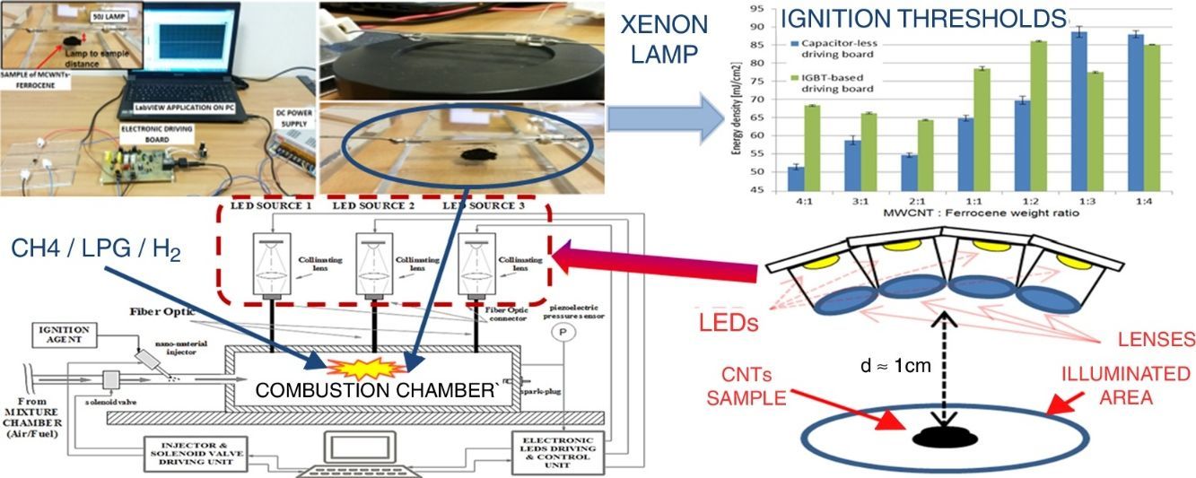
2Materials and methodsIn this paragraph, it is reported a characterization of the MWCNT/ferrocene ignition process, in terms of the required minimum ignition energy (MIE) of Xe light pulse, for different concentrations by weight of the mixture itself; subsequently, the mixture behavior when subjected to two light pulses, one after the other, will be discussed. The carried out experimental tests (experimental setup shown in Fig. 1b) concerned the photo-induced ignition of MWCNTs/ferrocene mixtures (an amount of ∼6.5mg) by varying mixture's weight ratio and Xe light pulse time duration and luminous intensity applied on the sample, in order to find the energy threshold value for each weight ratio. The luminous energy emitted by the 50J Xe flash lamp was measured by using the light energy meter (model PM100D, shown in Fig. 1a) and the pyroelectric sensor (model ES145C), both provided by Thorlabs, with a distance lamp-sensor of 4mm (as shown in Fig. 1c); then, each time, the pyroelectric sensor was replaced with the MWCNTs/ferrocene mixture (Fig. 1d) preserving the same distance lamp-sample to perform the ignition test.
, realized setup used to carry out the ignition tests (b), pyroelectric sensor model ES145C with Xenon lamp positioned above at a distance of 4mm (c) and Xe lamp on the sample at the same distance (d).")
The photo-ignition tests were performed making use of properly realized driving boards; in particular of the driving board that employs an IGBT switch for adjusting the pulse time length as function of the signal applied to the IGBT gate and afterwards of the ac-powered driving board characterized by the absence of a storage capacitor. This last, by acting on a potentiometer, allows to regulate the luminous energy emitted by the lamp (Visconti et al., 2016). In the first tests campaign the driving board with the IGBT was employed; it was triggered by a pulsed signal coming from a PC and was provided of a potentiometer (RPOT) used to adjust the desired time duration of the light pulse (Primiceri, Visconti, Longo, Tramis, & Carlucci, 2016). The luminous energy was determined as average of four measured energy values, each flash repeated after 10s (to give enough time for fully recharging of storage capacitor).
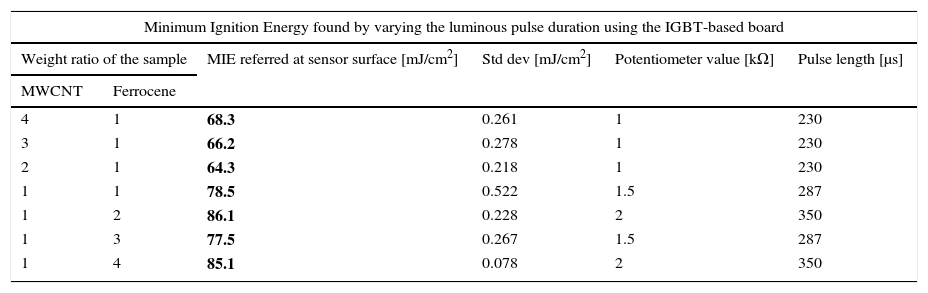
From measured energy values, captured by the whole sensor area (15.9cm2), able to ignite the MWCNT/ferrocene mixtures with different weight ratio, the luminous energy density (mJ/cm2) was calculated. As result of photo-ignition tests, Table 1 reports the obtained minimum ignition energy (MIE) and the relative standard deviation, together with the RPOT potentiometer value and the related pulse time length. The ignition tests started with a pulse energy well below that required for ignition and then it was progressively increased with small steps (arising the potentiometer value of 0.5kΩ each time) until the onset of ignition was detected, obviously replacing the not ignited sample with a new one each time.
MIE values for different concentrations of MWCNT/ferrocene mixture (from 4:1 to 1:4) using the IGBT-based driving board.
| Minimum Ignition Energy found by varying the luminous pulse duration using the IGBT-based board | |||||
|---|---|---|---|---|---|
| Weight ratio of the sample | MIE referred at sensor surface [mJ/cm2] | Std dev [mJ/cm2] | Potentiometer value [kΩ] | Pulse length [μs] | |
| MWCNT | Ferrocene | ||||
| 4 | 1 | 68.3 | 0.261 | 1 | 230 |
| 3 | 1 | 66.2 | 0.278 | 1 | 230 |
| 2 | 1 | 64.3 | 0.218 | 1 | 230 |
| 1 | 1 | 78.5 | 0.522 | 1.5 | 287 |
| 1 | 2 | 86.1 | 0.228 | 2 | 350 |
| 1 | 3 | 77.5 | 0.267 | 1.5 | 287 |
| 1 | 4 | 85.1 | 0.078 | 2 | 350 |
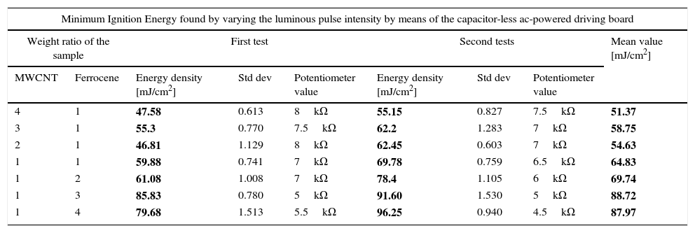
In the second test campaign, MWCNTs/ferrocene ignition tests were performed by employing the other driving board typology; it is a capacitor-less ac-powered driving board which allows, by acting on a suitable potentiometer, to change the luminous intensity emitted by the lamp. Therefore, we modified the energy emitted by lamp starting with low energy values, first delivered on the sensor and then on the mixture, piloting a single pulse by PC. Hence, we increased the pulse energy until the ignition phenomenon was observed, replacing, as well as the previous tests, the mixture not ignited, each time, with a new one. The procedure was carried out, for each weight ratio, from 4:1 to 1:4 (MWCNTs: ferrocene). Two test days were performed and the results, reported in Table 2, show that the mixtures with higher MWCNTs amount respect to ferrocene require lower energy to be ignited.
Minimum ignition energy [mJ/cm2] required to ignite each concentration of the mixture from 4:1 to 1:4. The mean value is obtained from the first and second test campaign.
| Minimum Ignition Energy found by varying the luminous pulse intensity by means of the capacitor-less ac-powered driving board | ||||||||
|---|---|---|---|---|---|---|---|---|
| Weight ratio of the sample | First test | Second tests | Mean value [mJ/cm2] | |||||
| MWCNT | Ferrocene | Energy density [mJ/cm2] | Std dev | Potentiometer value | Energy density [mJ/cm2] | Std dev | Potentiometer value | |
| 4 | 1 | 47.58 | 0.613 | 8kΩ | 55.15 | 0.827 | 7.5kΩ | 51.37 |
| 3 | 1 | 55.3 | 0.770 | 7.5kΩ | 62.2 | 1.283 | 7kΩ | 58.75 |
| 2 | 1 | 46.81 | 1.129 | 8kΩ | 62.45 | 0.603 | 7kΩ | 54.63 |
| 1 | 1 | 59.88 | 0.741 | 7kΩ | 69.78 | 0.759 | 6.5kΩ | 64.83 |
| 1 | 2 | 61.08 | 1.008 | 7kΩ | 78.4 | 1.105 | 6kΩ | 69.74 |
| 1 | 3 | 85.83 | 0.780 | 5kΩ | 91.60 | 1.530 | 5kΩ | 88.72 |
| 1 | 4 | 79.68 | 1.513 | 5.5kΩ | 96.25 | 0.940 | 4.5kΩ | 87.97 |
In the following frames (Fig. 2) the evolution over time of the combustion process is shown with indication of the time intervals during the combustion itself.

In order to compare the experimental results, obtained varying both pulse time duration (employing the ac powered IGBT-based driving board) and luminous energy intensity (using the ac powered driving board without a storage capacitor), the following histograms (Fig. 3) show the found MIE values making use of the two employed driving boards.

As shown in Figure 3, the obtained energy thresholds have a similar trend as function of MWCNT/Ferrocene weight ratio, even if a little higher MIE for all concentrations using the IGBT-based driving board was found, except for the mixtures with higher ferrocene amount (i.e. 1:3 and 1:4 ratios).
This experimental result is unexpected if compared with those found in literature where it is reported that a higher content of ferrocene facilitates the ignition. However, the photo-sensitive material used in our experimental tests is different from that used in literature; in this work, we have used MWCNTs-ferrocene mixtures while, in already published research works, samples of SWCNTs with 50% (by weight) Fe contents were tested (Badakhshan & Danczyk, 2014; Chehroudi, 2012b).
2.2MWCNTs/ferrocene mixture ignition using two repetitive flashesDuring the experimental tests, it was observed that, for energy levels lower than the threshold, the ignition was not triggered at first flash, but, by providing to the same mixture a further light pulse, the ignition was obtained. Therefore, for investigating this phenomenon, two flashes, the second flash after some seconds, were applied on the same mixture (2:1 and 1:3 were the mixtures used as sample for this test). Table 3 shows the flash time duration depending on the resistance value RPOT and thus the energy of the incident light on the mixtures. Starting with energy levels lower than the threshold (corresponding to 1kΩ value of the potentiometer RPOT), no mixture was ignited at first flash pulse, while at second flash the ignition was observed only for the 2:1 mixture, as reported in blue in Table 3.
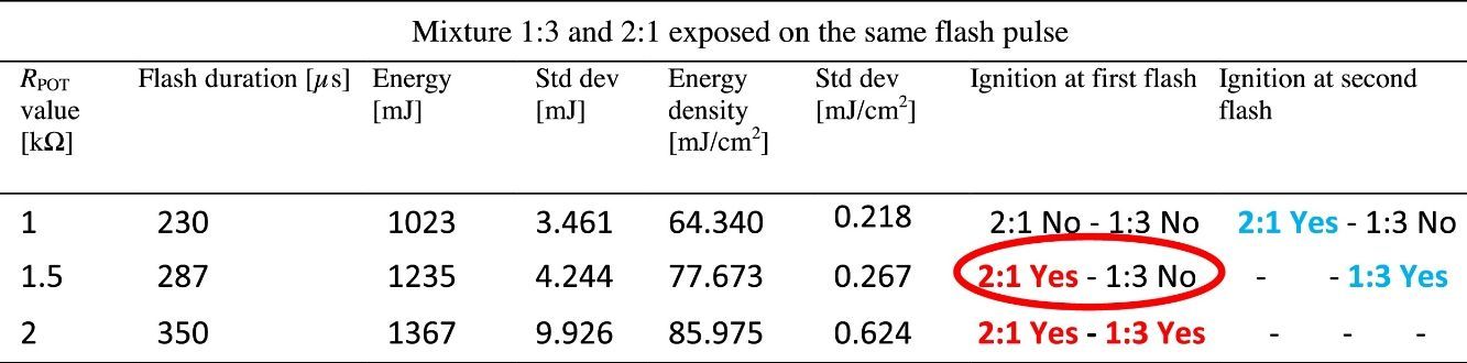
For the potentiometer value of 1.5kΩ, 2:1 mixture was ignited at first flash (red circle), while for the 1:3 one the ignition was obtained only at second flash. With potentiometer value of 2kΩ, the ignition was triggered for all the mixtures at first flash pulse. The following Figure 4 shows the frame sequence of the ignition test with potentiometer value equal to 1.5kΩ; it can be noticed that the ignition occurs only for the 2:1 (MWCNTs:ferrocene) mixture while it is absent for the 1:3 one. The 2:1 mixture appears greater than 1:3 because of the larger amount of CNTs respect to ferrocene contained within, being the CNTs more voluminous than ferrocene.

In order to explain and clarify this mixture behavior (i.e. the light energy thresholds are lower at the second flash), some discussions, considering the studies present in the literature, are reported below. Published research works report that the photo-induced ignition occurs, in air, for different types of SWCNTs, prepared with different methodologies and percentages of CNTs (in the range 50–90% by weight) with respect to the metal catalyst (Fe) mixed with them. The authors of these studies conjectured that the ignition and combustion occur when there is local increase of temperature sufficient to initiate the oxidation of carbon; their interpretation was that SWCNTs lend themselves to this photo-effect thanks to their black color, so allowing to better absorb the flash light and transmit the resulting thermal energy in their structure inside the Fe nanoparticles. The local transient high temperature inside the nanotubes has to be at least ∼1500°C, so that a structural reconstruction process can take place with the SWCNT structure permanently changed to a non-nanotube structure, rather than a merely elastically deforming. Furthermore, this reconstruction also happens after flash exposure even if ignition and combustion do not occur (Ajayan et al., 2002). For these reasons we performed all the previous tests, as previously mentioned, by replacing the mixture not ignited, each time, with a new one and taking into account, as shown in Table 3, when the second flash was applied on the same mixture. With reference to the studies reported in literature, it was found that the incident light on the sample, having an energy not sufficient to trigger the ignition, induces a process that facilitates the ignition of the mixture when exposed to a second flash. In order to confirm this thesis, a further test was carried out making use of the IGBT-based driving board: for each MWCNTs:ferrocene mixture weight ratio, we exposed the mixture to a pulsed light with subthreshold luminous energy observing, as expected, absence of ignition. After about 10s, to give enough time for fully recharging of storage capacitor, the same mixture was exposed to a second flash, triggering in this case the ignition. Therefore, the obtained results are in agreement and confirm the studies aforementioned, reported in literature. In Figure 5, a comparison of the MIE needed to ignite the samples, with a single flash and with two repetitive flashes, is reported.

The activation energy, when two flashes are used to ignite the sample, is lowered of about 24% (for 1:2 MWCNTs: ferrocene weight ratio) and of about 15% (for 2:1 MWCNTs: ferrocene mixture weight ratio) compared to the MIE values needed to activate the ignition using a single flash.
3Results and discussionThe discovery of the photo-ignition phenomenon of SWCNTs or MWCNTs enriched with metal nano-particles presents considerable practical and commercial implications such as to attract significant interest from companies and international research organizations, first of all of those operating in the automotive and aeronautical field. In fact, the ignition phenomenon can be employed for triggering the combustion of solid, liquid and gaseous fuels (Badakhshan & Danczyk, 2014; Badakhshan, Danczyk, Wirth, & Pilon, 2011; Badakhshan & Danczyk, 2011; Chehroudi, 2011, 2012b). Furthermore, the photo-ignited nanoparticles allow to obtain a more distributed and homogeneous fuel combustion (Carlucci et al., 2014; Carlucci & Strafella, 2015; Johansson, 2007). This innovative method for triggering the fuel combustion, if it will be implemented, will become very important for the internal combustion engines, but also for other related applications, in the future (Zhao, 2007).
3.1MWCNTs/ferrocene ignition for triggering the combustion of different gaseous fuelsSeveral tests were carried out demonstrating how the combustion of different gaseous fuels, triggered by using the nanoparticles as ignitor agents, presents better performances compared to those obtained by using the traditional spark plug, in which case the combustion is triggered in a single point and proceeds with a flame front propagation. On the contrary, if the nanoparticles are used, the combustion is triggered simultaneously in multiple points within the combustion chamber; hence, higher peak pressure, lower ignition delay and combustion duration are obtained. As example, Figure 6 shows the pressure curves acquired by triggering the combustion of an air-methane mixture, with an air-fuel equivalence ratio λ=1.02, by using MWCNTs or spark-plug as igniters; starting from an initial value of 3bar inside the combustion chamber, the pressure reaches about 21bar for combustion triggered by MWCNTs and about 19bar for the one triggered by the spark. From these curves it is possible to get, besides the reached pressure values, also the ignition delay and the combustion duration values (Carlucci & Strafella, 2015).
 triggered by using MWCNTs or spark plug.")
Further tests were carried out in (Carlucci et al., 2016); by using the MWCNTs with 75% of ferrocene by weight, in order to investigate the combustion process of air/methane fuel, the air/fuel equivalence ratio was varied in the range [1.02–1.97], whereas the amount of used nanoparticles for triggering the fuel combustion, was also changed from 20mg to 150mg. The pressure measurements show that by increasing the CNTs amount in the fuel mixture, the rise time of the pressure curve remains unchanged, whereas the peak pressure tends to increase probably because of the greater quantity of ignition nuclei inside the combustion chamber. The obtained data highlighted that the combustion triggered with nanoparticles presents a more rapid growth of the pressure curve and an higher peak pressure value, with consequently greater heat released during combustion process compared to that released when the spark is used.
For triggering the combustion of different gaseous fuels (CH4, LPG and H2), we realized a proper experimental setup, shown in Figure 7. It is composed of a combustion chamber, made of low carbon steel, with cylindrical shape, provided of separate accesses for a piezo-resistive pressure sensor, an exhaust line and a duct for the air/fuel mixture supply, enriched with the nanoparticles. In particular, by means of a solenoid valve, the mixture amount is introduced into the combustion chamber, after being heated by a Joule effect heater into the mixture chamber. Subsequently, passing through the duct, the fuel mixture is enriched with nanoparticles, placed into the CNT holder, and reaches the combustion chamber. Here the fuel combustion is triggered by the Xe lamp, placed inside the chamber, or by the traditional spark plug; this allows to compare the combustion processes ignited by Xe lamp luminous pulse (by using nanoparticles) with those resulting from the use of spark plug (without nanoparticles).

By using the experimental setup reported in Figure 7 and the optimized parameters of Xe flash (namely flash time duration and luminous energy density), for triggering CNT ignition, as found in experimental tests reported in “Materials and methods” section, the combustion tests, induced by nanoparticles photo-ignition, of different gaseous fuels were carried out. In addition, from results previously reported, the optimum MWCNTs/ferrocene ratio by weight and amount to be employed in combustion tests, have been determined.
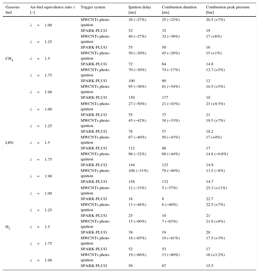
In Table 4, the results of combustion processes obtained by using CH4, LPG and H2 gaseous fuels enriched with nanoparticles are reported; also the comparison with combustion features resulting from the spark-plug-induced ignition process, is shown. The obtained results highlighted that higher peak pressure, lower ignition delay and shorter combustion duration are obtained by using the MWCNTs photo-ignition, rather than spark-plug, as triggering system. These combustion features were observed for all the tested fuels and for different values of the air-fuel equivalence ratio λ (Carlucci et al., 2016).
Results and comparison of the combustion processes of different gaseous fuels (CH4, LPG and H2) by employing nanoparticles as ignitor agents or the traditional spark-plug.
| Gaseous fuel | Air-fuel equivalence ratio λ [–] | Trigger system | Ignition delay [ms] | Combustion duration [ms] | Combustion peak pressure [bar] |
|---|---|---|---|---|---|
| CH4 | λ=1.00 | MWCNTs photo-ignition | 38 (−27%) | 25 (−22%) | 20.5 (+7%) |
| SPARK-PLUG | 52 | 32 | 19 | ||
| λ=1.25 | MWCNTs photo-ignition | 40 (−27%) | 32 (−36%) | 17 (+6%) | |
| SPARK-PLUG | 55 | 50 | 16 | ||
| λ=1.5 | MWCNTs photo-ignition | 50 (−30%) | 45 (−29%) | 15 (+1%) | |
| SPARK-PLUG | 72 | 64 | 14.8 | ||
| λ=1.75 | MWCNTs photo-ignition | 70 (−30%) | 74 (−17%) | 12.7 (+5%) | |
| SPARK-PLUG | 100 | 90 | 12 | ||
| λ=1.98 | MWCNTs photo-ignition | 95 (−36%) | 81 (−54%) | 10.5 (+5%) | |
| SPARK-PLUG | 150 | 177 | 10 | ||
| LPG | λ=1.00 | MWCNTs photo-ignition | 27 (−50%) | 21 (−43%) | 23 (+9.5%) |
| SPARK-PLUG | 55 | 37 | 21 | ||
| λ=1.25 | MWCNTs photo-ignition | 45 (−42%) | 38 (−33%) | 19.5 (+7%) | |
| SPARK-PLUG | 78 | 57 | 18.2 | ||
| λ=1.5 | MWCNTs photo-ignition | 67 (−40%) | 50 (−43%) | 17 (+0%) | |
| SPARK-PLUG | 112 | 88 | 17 | ||
| λ=1.75 | MWCNTs photo-ignition | 98 (−32%) | 68 (−44%) | 14.8 (−0.6%) | |
| SPARK-PLUG | 144 | 123 | 14.9 | ||
| λ=1.98 | MWCNTs photo-ignition | 108 (−31%) | 79 (−40%) | 13.5 (−8%) | |
| SPARK-PLUG | 158 | 132 | 14.7 | ||
| H2 | λ=1.00 | MWCNTs photo-ignition | 12 (−33%) | 5 (−37%) | 25.3 (+11%) |
| SPARK-PLUG | 18 | 8 | 22.7 | ||
| λ=1.25 | MWCNTs photo-ignition | 13 (−48%) | 6 (−40%) | 22.5 (+7%) | |
| SPARK-PLUG | 25 | 10 | 21 | ||
| λ=1.5 | MWCNTs photo-ignition | 15 (−60%) | 7 (−63%) | 21.6 (+8%) | |
| SPARK-PLUG | 38 | 19 | 20 | ||
| λ=1.75 | MWCNTs photo-ignition | 18 (−65%) | 10 (−81%) | 17.5 (+3%) | |
| SPARK-PLUG | 52 | 53 | 17 | ||
| λ=1.98 | MWCNTs photo-ignition | 19 (−66%) | 13 (−80%) | 16 (+3.2%) | |
| SPARK-PLUG | 56 | 67 | 15.5 | ||
Furthermore, in the table, the percentage values related to the improvements of peak pressure, ignition delay and combustion duration obtained by using CNTs photo-ignition respect to spark-plug ignition, for each tested fuel and λ value, are shown. The comparison between the different combustion processes, using nanoparticles and spark-plug, was obtained by acquiring the pressure values reached inside the combustion chamber, by means of the used piezo-resistive pressure sensor; by dynamic pressure measurements, the ignition delay and combustion duration were obtained, as shown in Figure 6.
The use of nanoparticles, compared to the spark, allows to have, taking into account as example λ=1, a higher peak pressure of about 7% for the CH4 fuel, of about 9.5% for LPG and of 11% with the H2 fuel. For the ignition delay, an improvement of about 27% was obtained for CH4, whereas for LPG the ignition delay is better by 50% respect to the combustion with the spark and relatively to H2 the improvement is of the 33%. Considering the combustion duration, in the case λ=1 as example, the value decreases from 32ms to 25ms thus obtaining an improvement of 22% for the CH4, from 37ms to 21ms for LPG, with a shorter combustion duration of 43% and finally, the improvement for H2 fuel is of 37%, with a combustion duration reduced from 8ms to 5ms. Also for other λ values, the combustion features improvements, relatively to peak pressure, ignition delay and combustion duration, are preserved for all the tested fuels. Nevertheless, by increasing λ, i.e. burning leaner mixtures, the pressure gradient and pressure peak decrease; the latter is also delayed. Only for the LPG with λ=1.75 and λ=1.98, it is observed a slight decrease of the peak pressure reached with CNT photo ignition respect to spark ignition, even if the values are very similar.
Related to air/H2 fuel mixture, the combustion process presents higher peak pressure and shorter ignition delay and combustion duration compared to other two gaseous mixtures, for all tested conditions. This is due to the lower heating value of H2 (119.93MJ/kg), higher than that of methane (50.02MJ/kg) and LPG (46.2MJ/kg) and to higher flame speed than methane and LPG ones. In addition, the ignition delay is smaller because minimum ignition energy value required to ignite H2 is ≈0.02mJ while those of CH4 and LPG are 0.3mJ and 0.26mJ respectively.
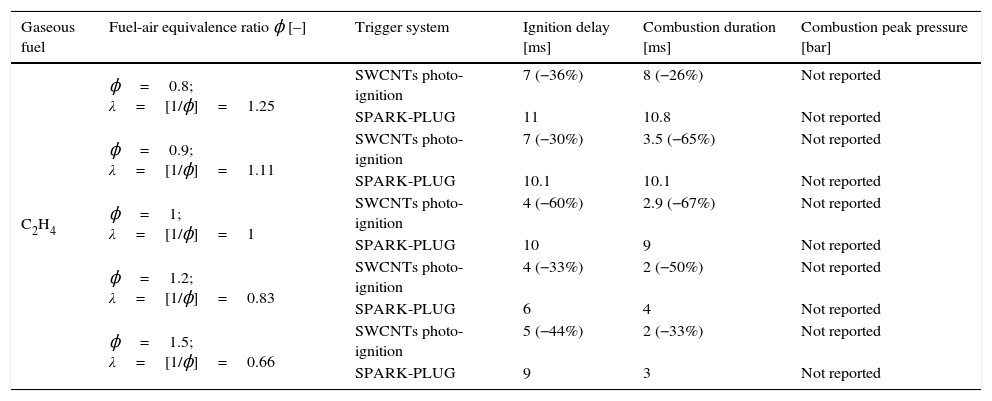
These reported results confirm that the combustion triggered by using the nanoparticles presents better performances respect to the one triggered by the spark and they are in agreement with results reported in (Berkowitz & Oehlschlaeger, 2011), where, however, an ethylene/air mixture was ignited by employing SWCNT with 70% Fe impurity by weight as ignitor agents. Furthermore, the results were compared with those obtained with the spark-plug. The authors made use of an experimental setup consisting of a combustion chamber with inside a Xenon lamp, a piezoelectric transducer, an injector for providing the air-nanomaterial mixture, a quartz window in order to capture frames related to the combustion evolution and finally, the gas duct and a spark plug. Table 5 reports the results of the combustion processes of C2H4 obtained by photo-igniting the SWCNTs, mixed with the fuel, and by means of the spark.
Results of the combustion processes of ethylene/air fuel mixture by employing SWCNTs nanoparticles as ignitor agents and comparison with results obtained with the traditional spark-plug.
| Gaseous fuel | Fuel-air equivalence ratio ϕ [–] | Trigger system | Ignition delay [ms] | Combustion duration [ms] | Combustion peak pressure [bar] |
|---|---|---|---|---|---|
| C2H4 | ϕ=0.8; λ=[1/ϕ]=1.25 | SWCNTs photo-ignition | 7 (−36%) | 8 (−26%) | Not reported |
| SPARK-PLUG | 11 | 10.8 | Not reported | ||
| ϕ=0.9; λ=[1/ϕ]=1.11 | SWCNTs photo-ignition | 7 (−30%) | 3.5 (−65%) | Not reported | |
| SPARK-PLUG | 10.1 | 10.1 | Not reported | ||
| ϕ=1; λ=[1/ϕ]=1 | SWCNTs photo-ignition | 4 (−60%) | 2.9 (−67%) | Not reported | |
| SPARK-PLUG | 10 | 9 | Not reported | ||
| ϕ=1.2; λ=[1/ϕ]=0.83 | SWCNTs photo-ignition | 4 (−33%) | 2 (−50%) | Not reported | |
| SPARK-PLUG | 6 | 4 | Not reported | ||
| ϕ=1.5; λ=[1/ϕ]=0.66 | SWCNTs photo-ignition | 5 (−44%) | 2 (−33%) | Not reported | |
| SPARK-PLUG | 9 | 3 | Not reported |
Reported results show that the combustion occurs in an almost homogeneous way in the combustion chamber, without a discernible flame-front, as also reported in (Carlucci & Strafella, 2015). Furthermore, by comparing the combustion processes triggered by the CNTs and by the spark, on the basis of the measurements of dynamic pressure and in lean mixture conditions (ϕ=[1/λ]<1), the ignition delay and the rise time of the pressure curve are shorter respect to the same parameters found by employing the spark (Carlucci et al., 2017).
In particular, using the fuel/air equivalent ratio of ϕ=1, the tests performed with the initial pressure value, inside the combustion chamber, equal to 1bar and then with an initial pressure value of 2bar, show that the values relative to the ignition delay and rise time are shorter of about 60% using the CNTs trigger system rather than the spark.
3.2Automotive and new potential applications of CNTs photo-ignitionAn investigation on the possible applications of the CNTs photo-ignition in the automotive industry and beyond, is reported below. Taking into account that the use of nanoparticles, as trigger sources of fuels mixture inside a combustion chamber, allows to obtain a more distributed ignition, a possible application field is that of liquid rocket booster (LRB) (Chehroudi, 2011). In fact, about the 30% of the combustion process instabilities, which could lead to engine failure, depend on the ignition trigger features; a distributed ignition technology becomes an optimal strategy for triggering the combustion in this type of motors (rocket engines) allowing an homogeneous and controlled fuel combustion. This new technology is desirable even in the satellites engines realization, where low weight, small dimension and low power are among the fundamental requirements (Chehroudi & Danczyk, 2006; Chehroudi, 2011).
By using SWCNTs with different concentration of Fe by weight, as nanomaterial photo-sensible, the authors in (Badakhshan et al., 2011; Badakhshan & Danczyk, 2011) analyzed the ignition of spray liquid fuels and of solid rocket fuels (SRF). They realized an Ignition Capsule in transparent plastic material, with diameter equal to 7mm and length of 20mm (volume equal to 0.75cm3), containing the CNTs sample; with the suitable amount of nanomaterial inside the capsule, by triggering the ignition by means of the light pulse, the released gas (CO2 and CO) pressurized the capsule. When the pressure value exceeded 30 PSI, the capsule broke and the burning nanomaterial, by coming into contact with the fuel, triggered the combustion. Afterwards, the minimum ignition energy required for triggering the nanoparticles photo-ignition inside the capsule was determined. Then, by locating the “ignition capsule” on the nozzle path of an ultrasonic atomizer, used to generate the fuel spray (Hexane with 50% Acetone), the liquid-fuel combustion was obtained. Furthermore, the authors tested this typology of ignition capsule for igniting solid fuel, thus simulating the SFR ignition. By mixing a fuel with an oxidizing element, the solid fuel was produced and then placed inside a cylinder designed in order to burn from inside out in high temperature and pressure conditions. Thus, the simulated SRF photo-ignition was successfully obtained, by photo-igniting the CNTs, with a fast combustion in a way very similar to the typical SRF one (Badakhshan et al., 2011; Badakhshan & Danczyk, 2011). However, the CNTs photo-ignition is an advantageous solution for combustion of both SRF and liquid rocket fuel (LRF), thanks to the particular method for triggering the combustion itself, i.e. the light pulse rather than traditional ignition techniques such as ferrous spark generators, electrical contacts and pilot flame systems. In fact, these traditional techniques present some problems in particular operating environments, for example under vacuum conditions, where the spark doesn’t burn and where the pilot flame presence represents a further complexity for the ignition system. In addition, by mixing the CNTs with nanoparticles and powdered material, the possibility to modify the combustion parameters such as combustion temperature and duration was demonstrated in (Badakhshan et al., 2011). Furthermore, the possibility to control the thrust directionality of a solid rocket fuel was successfully investigated; in fact, by realizing rocket prototypes consisting of glass cylinders (borosilicate) containing either SWCNTs with 50% by weight of Fe impurities or MWCNTs with 25–30wt.% ferrocene impurities, the combustion of SRF was obtained. Oxidizers such as ammonium perchlorate (NH4ClO4) and potassium permanganate (KMnO4) were also used to accelerate the combustion, whereas, the employed solid fuels included ferrocene (Fe(C5H5)2) and titanium hydride (TiH2). By considering a matrix composed of these realized rockets and a Xenon lamp (300Ws), it was possible to trigger the combustion selectively, restart it by photo-igniting some rockets of the matrix rather than others and finally, in the same way, to give a direction to the rocket thrust (Badakhshan et al., 2011; Bastian & Roberts, 1982).
A further application field of the CNTs photo-ignition concerns the flame stabilization inside the gas turbines (Fig. 8), avoiding, in this way, the needed of a recirculation zone for the flame stabilizing inside the combustor (Chehroudi, 2011). The distributed ignition presents advantageous for turbine engines of aircraft; in fact, the motor restart, in high-altitude, is a critical operation when the stabilized flame is blown away from the combustion chamber, hence, if multi-ignition points are available, inside the combustor, the motor shutdown is more difficult to occur.
.")
Cross-section of a gas turbine aircraft engine; a distributed ignition inside the combustion chambers allows to avoid the engine shutdowns in critical conditions (original image taken from https://en.wikipedia.org/wiki/File:Jet_engine.svg; it was created by Jeff Dahl and reported also in Airplane Flying Handbook 2004, U.S. Department of Transportation Federal Aviation Administration, Chapter 14 – Transition to Turbo-propeller Powered Airplanes).
Further possible applications, different from those related to the fuels combustion, concern the use of photo-induced CNTs ignition in the field of explosive materials (Finigan, Dohm, Mockelman, & Oehlschlaeger, 2012). As example, the photo ignition of SWCNTs by a common Xe-lamp, was employed for triggering the detonation of energetic materials, placed in contact with the nanoparticles, as reported in (Manaa, Mitchell, Garza, Pagoria, & Watkins, 2005). The principal advantages of an optical initiation and ignition of energetic materials are related to the immunity of an optical source to the electromagnetic interferences and to the variation of temperature and pressure conditions. Furthermore, the light pulses generation doesn’t depend on the material conditions which might degrade over time. The obtained results offer new prospects to the use of CNTs for triggering the energetic materials explosion; some applications regard the firing of bolts on space shuttle rockets, aircraft exit doors and controlled burning of explosives as energy actuators (Manaa et al., 2005).
A very similar system was conceived in (Badakhshan, 2017), in which a versatile ignition platform, optical and ultra-compact called Photo-Ignition Tourch (PITCH), was designed in order to initiate chemical reactions such as combustions, detonations and gas generation for rapid chamber pressurizations. This PITCH system uses the photo-ignition, induced by a Xenon flash lamp, of nanostructured carbon-based materials inserted into an ignition capsule containing combustible materials (solid fuels/propellant), which can be customized as function of the specific applications. Indeed, this system allows to set the combustion or detonation parameters, including the main solid fuel type inserted into the capsule, ignition speed, time duration and flame length (>15cm). In addition, for gas generation applications, the amount of the generated gases and their temperature can be controlled. Even if the device was designed to test the rockets ignition stability, many other applications can be proposed for this device typology; for example air space, satellites applications, rapid gas generators, devices for the fast airbags inflating or rapid containers pressurization and for restarting turbine/combustor with a near-zero delay.
Finally, a further innovative application, concerning the automotive field, is related to the periodic clean of catalytic exhausts of vehicles. The operating of a catalytic converter is very similar to that of high pressure carbon oxide process (HiPCo), method used by industries for producing CNTs; hence, the formation of CNTs (both SWCNTs and MWCNTs) could occur in the honeycomb structure of the catalyst (Ayre et al., 2011; Deng et al., 2016; Pander, Hatta, & Furuta, 2016; Rümmeli et al., 2011). Furthermore, the metal nanoparticles, essential for obtaining the photo-ignition, can be added to those already present (i.e. platinum and rhodium) in modern catalytic exhausts to perform the catalyst action (Qi, 2016). Then, by placing a pulsed light source inside the catalytic converter, is possible to photo-ignite the CNTs generated within it, for triggering the combustion of the present residues, allowing to easily expel them from the structure, thus regenerating the drain.
3.3Technical limitations of Xenon lamp-based solution and future developments by using white LEDsEven if the CNTs ignition phenomenon was observed for the first time by employing a Xenon lamp as light source, which is still the used light source for triggering the CNTs ignition, the Xe lamp presents several problematics relatively to its employment in some applications; first of all related to the automotive field. Considering the operating principle of Xe lamps, discharge lamps, they require high voltage values both for feeding but also for the trigger signal useful to ionize the gas inside the lamp. These voltage values can be obtained from the voltage value provided by a battery (12V), by means of a DC-DC step-up converter; this involves the disadvantage of straining the battery and consequently to reduce its life-time. Furthermore, in the automotive environment, it is preferable to avoid the use of high voltage values and related driving circuitry, because of the presence of highly flammable substances very close to the mechanical/electronic apparatus.
The second issue is related to the location of the Xe lamp; in fact, in the current application scenario for triggering the CNTs ignition and hence the fuel combustion, the lamp is placed inside the combustion chamber, thus working in a very hostile environment due to the high temperature, pressure, corrosion substances, exhausts products etc. Furthermore, after short time, the glass lamp tube tends to blacken and consequently the emitted light is shielded, thus the provided luminous power significantly reduced.
However, one of the main limits related to the use of Xe lamps, for automotive application, concerns the lamp life-time; the lamp aging, in fact, affects the emitted light intensity and the trigger ability. The lamp life-time depends on several factors such as flash energy, anode voltage, flash-rate, cooling conditions etc.; all these elements are amplified if the Xe lamp operates inside the combustion chamber.
Moreover, the lamp life-time decreases by increasing the energy on the lamp (for example energy provided by the storage capacitor); it exists a certain energy value for which, by fixing the lamp dimension and providing a single pulse, the lamp explosion occurs (named Explosion energy). For ensuring a long lamp lifetime, the energy provided to it should not overcome the 50% of the explosion energy value. By providing energy values in the range of 10–20% respect to the explosion energy value, then the estimated life-time reaches about one million of light pulses. This number of light pulses, which a Xe lamp can emit on average in its life-time, is very low for automotive application; in fact, by supposing that a motor (for example four-stroke), operates to 2500rpm (or 4000 in the worst case), the ignition system, and thus the Xe lamp, must emit 1250 light pulses over one minute (2000 pulses in worst case). In this way, the system operation is ensured for a number of hours equal to Operation hours=106/(1250×60)=13.33 h, or in the worst case (4000rpm and 2000 pulses) equal to Operation hours=106/(2000×60)=8.33 h. Obviously, in the effective operating conditions, i.e. inside the combustion chamber, the lamp lifetime is reduced significantly respect to the calculated number of hours.
A further limit, related to the employment of the Xe lamp for triggering the fuel combustion, is the obtainable flash-rate; an internal combustion engine requires an operating frequency of the triggering source (spark plug or Xe lamp) up to 40–50Hz. Due to the absence of circuital solutions for driving the Xe lamp at these frequency values, this flash rate is not achievable; in fact, the operation of these driving circuits is based on the charge of the storage capacitor to several hundred volts. Therefore, the flash rate depends on the charging time of the storage capacitor, whereas, by using the circuit architecture “less-capacitor”, even if higher frequency values can be reached, respect to the previous solution, they are still lower than the necessary.
Accordingly, the issues previously discussed lead to focus the attention on other luminous source typologies to have a more robust and realizable solution in the different application fields. Relatively to the automotive application, the LED-based light sources, for replacing the Xe lamps, are excellent candidates, taking also into account the rapid development in the semiconductor technological area in the last years. LEDs technology, in fact, has reached over time excellent properties in terms of luminous output power, efficiency, reliability, operating safety etc. The use of LED sources, as explained below, allows to overcome the previously mentioned disadvantages related to the use of Xe lamp. In first instance, LEDs have very high luminous efficiency, reaching up to 150 lumen/W than a Xe lamp, that provides about 40–50 lumen/W, with consequently lower power consumption. Furthermore, LEDs require a different driving mechanism, allowing to use driving voltages much lower than those used for Xe lamps; this results in a major safety of use, besides an easier driving. Moreover, for triggering the CNTs ignition and so the fuel combustion, it is more practical to place LED sources away from the combustion chamber and to lead the generated light inside the chamber by means of optical fibers, also by using suitable optical lenses for collimating the emitted light beam. LEDs have smaller dimensions and greater mechanic stability than Xe lamp, they are compact devices, suitable to be employed into a mechanical apparatus subjected to vibration and mechanical stress.
A further advantage of LEDs is their life-time, which is significantly longer than that of the Xe lamps; the Alliance for Solid State Illumination Systems &Technologies (ASSIST) defines the life-time of a LED device, as the time period beyond which the output light decreases by 70% respect to the initial lumen value (denoted as L70). According to this definition, the main producers of high power white LED declare an estimated average life-time between 50,000 and 100,000h. However, the life-time of a LED is function of the driving current and operative temperature. Another fundamental aspect regards the device switching (ON/OFF); it doesn’t affect the life-time, as on the contrary it occurs with a Xe lamp.
Furthermore, by using LED sources, it is possible to generate light pulses with frequencies compatible with those required by the automotive application. As example, by supposing, in the worst case (high speed motor), that the motor operates at 4000rpm (≈66rps) and by considering that a four-stroke motor performs an explosion every two revolutions, then, the ignition system has to perform 2000 ignitions/minute (≈33ignitions/s). In this way, the LED source operates at 33Hz (with a period equal to about T=30ms). Hence, taking into account a time duration (of light pulse) for triggering the CNTs ignition equal to 10ms, the duty-cycle of the applied signal for driving the LED source is given by the following formula: D=TON/T=10 ms/30 ms=0.33=33%
LEDs can operate at frequencies up to MHz, therefore, the use of this light source typology, for triggering the combustion process, is not an issue from the point of view of the luminous pulses frequency, even because the operation of LED driving circuit is not based on the charge of a storage capacitor as for the Xe lamp.
In addition, a multi-LED ignition system is able to variate in real time the turning on/off of some light sources rather than others, allowing to control and choose the areas, inside the combustion chamber, in which to trigger the ignition and then to start the combustion, so obtaining a better control of the combustion process. Besides, a LED-based source offers the advantage to easily adjust the emitted light intensity as function of the particular engine operative conditions, of the λ value, or of the nanoparticles amount dispersed in the fuel mixture. This kind of control can help the fuel consumption optimization depending on the engine operating conditions.
Finally, taking into account the different advantages, illustrated above, deriving from the utilization of a LEDs-based source, we propose here an experimental setup, shown in Figure 9, in which the use of LED sources allows to trigger the CNTs ignition and hence the combustion of liquid/gaseous fuels. The experimental setup, obtained by modifying that reported in Figure 7, is provided of three LED sources, arranged in different chamber points, which can be independently driven. Each light source is optically coupled, by means of an optic fiber, with the combustion chamber. The designed system allows to turn on/off each LED source, by means of a proper electronic driving control unit and to adjust the luminous intensity emitted by each light source; this allows to select the ignition region inside the combustion chamber, thus providing the possibility to optimize the control on the combustion process.

The proposed experimental setup is encouraged by already obtained CNTs photo-ignition, in our experimental tests by using high-power LEDs as light source. In the research works present in literature, different studies have been carried out to investigate the photo-ignition phenomenon; absorption spectra were obtained and photo-ignition tests performed in order to understand, also by varying the concentration MWCNTs/ferrocene by weight, the energy levels for triggering the CNTs photo-ignition. All these tests were carried out by using a Xe lamp as light source and never LED sources were employed (to our knowledge). In fact, the emitted luminous power, provided by the Xe lamp, is much higher compared to that obtainable from a LED source; LEDs are not able to provide, in a light pulse with time duration of few tens of milliseconds, the same luminous energy emitted by the Xe lamp. However, the technological developments, in the production of LEDs, are offering LED devices even more powerful and able to reach very high luminous flux levels.
Therefore, the first studies on the possibility to use LEDs, as trigger source for CNT ignition, are reported below; a proper experimental setup was realized to perform the ignition tests employing LED sources in place of Xe lamp. Figure 10a shows the used LED, model XHP70 produced by CREE, a leader company in the production of LED devices, which presents a maximum luminous flux equal to 4200 lumen, a maximum drive current of 2.4A and a supply voltage equal to 12V. By using a suitable structure provided of optical lenses for collecting and collimating the emitted light, four LED devices were put together, each of them with a proper lens, as reported in the principle scheme of Figure 10b.
, principle scheme with four LEDs put together in order to increase the luminous energy on the sample (b) realized setup for performing the photo-ignition tests (c) and MWCNTs/ferrocene samples positioned on a quartz plane before of the ignition test (d).")
LED XHP70 model produced by Cree (a), principle scheme with four LEDs put together in order to increase the luminous energy on the sample (b) realized setup for performing the photo-ignition tests (c) and MWCNTs/ferrocene samples positioned on a quartz plane before of the ignition test (d).
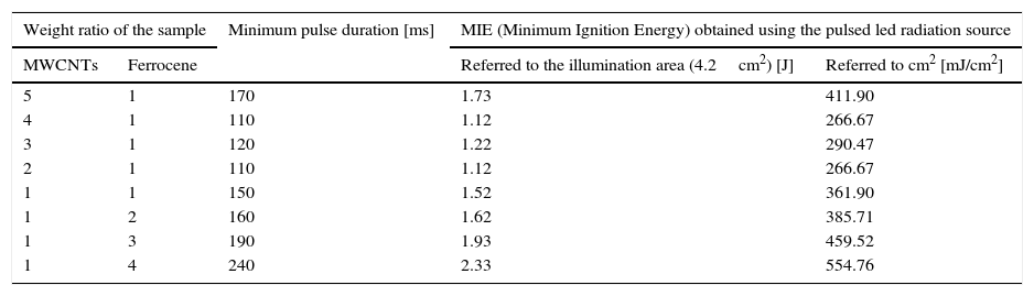
The ignition tests were carried out using the LED maximum driving current (2.4A) and a supply voltage for the LED driver of 16V (12V are required by LED device); the light spot covered a circular illumination area of diameter 3.5cm, featured by a higher luminosity intensity enclosed in the center with a circular area of diameter 1.5cm (corresponding to the sample location). The light source is placed at 1cm at least from the used pyroelectric sensor (Thorlabs ES145C) for measuring the light pulse energy and then from CNTs sample (Fig. 10c and d). Hence, utilizing the experimental setup shown in Figure 10c, photo-ignition tests were carried out for determining the minimum pulse durations needed to ignite the MWCNTs/Ferrocene samples for the different concentrations by weight (from 5:1 to 1:4). Finally, Table 6 reports the minimum pulse time duration needed to photo-ignite samples for the different used concentrations; in addition, also the MIE values related both to the whole illumination area (4.2cm2) and to the unit area (1cm2) are reported (being the light power of used LEDs-based source ≈ 10W).
Minimum time duration of the light pulses and related MIE values needed to ignite the samples for each MWCNTs:Ferrocene concentration by weight.
| Weight ratio of the sample | Minimum pulse duration [ms] | MIE (Minimum Ignition Energy) obtained using the pulsed led radiation source | ||
|---|---|---|---|---|
| MWCNTs | Ferrocene | Referred to the illumination area (4.2cm2) [J] | Referred to cm2 [mJ/cm2] | |
| 5 | 1 | 170 | 1.73 | 411.90 |
| 4 | 1 | 110 | 1.12 | 266.67 |
| 3 | 1 | 120 | 1.22 | 290.47 |
| 2 | 1 | 110 | 1.12 | 266.67 |
| 1 | 1 | 150 | 1.52 | 361.90 |
| 1 | 2 | 160 | 1.62 | 385.71 |
| 1 | 3 | 190 | 1.93 | 459.52 |
| 1 | 4 | 240 | 2.33 | 554.76 |
The results showed that the ignition is triggered with light pulses having time duration greater than 110ms and therefore energy density greater than 260mJ/cm2. Summarizing, by using LEDs as light source, the CNT photo-ignition was triggered, even if, the needed light pulse time duration, in order to reach on the sample the useful energy value for triggering the ignition, is still greater than 10ms (maximum time duration required by automotive applications, as discussed previously). Nevertheless, we suppose that, optimizing the LED-based setup, for example by collimating as much as possible the emitted light in order to collect the whole output light beam, will be possible to obtain the CNTs photo-ignition with a shorter time duration respect to the obtained one.
Finally, a detailed analysis of all the performed tests, employing the LEDs-based light source for triggering the gaseous fuels combustion into the combustion chamber, will be reported in the future.
4ConclusionsIn this research work an overview on the possible application fields, concerning the photo-ignition phenomenon of CNTs enriched with metal nanoparticles, is presented. Firstly, the results of experimental tests regarding the CNTs photo ignition, by using a Xenon lamp, are reported; by means of proper realized driving boards, for adjusting the parameters of emitted light pulse, the needed energy values useful for triggering the ignition were obtained. The experimental tests were performed varying the concentration by weight of the used samples (MWCNTs: ferrocene from 4:1 to 1:4). Subsequently, the combustion of different gaseous fuels enriched with nanoparticles was analyzed, reporting the obtained results and comparing them with those of other researcher works. The obtained values related to peak pressure, ignition delay and combustion duration, demonstrate that the use of CNTs, inside the fuel mixture, allows to get better features of the combustion process respect to the use of a traditional spark plug, for all the tested fuels.
Once shown these results, an investigation on the possible application fields, including automotive, aerospace and energetic materials, is reported; furthermore, the advantages deriving from the use of this trigger system are highlighted. In addition, a further application, concerning the cleaning of catalytic converters, is also suggested. Finally, considering the disadvantages of the use of the Xenon lamp for automotive applications but not only, we propose an innovative LED-based solution, in which the LEDs are used to trigger the CNTs ignition and hence the fuel combustion inside an experimental setup. In fact, the first experimental results, concerning the photo-ignition by means of LEDs devices, show that, even if with time duration of light pulse still high, the CNTs-ignition was obtained.
Conflict of interestThe authors have no conflicts of interest to declare.
Peer Review under the responsibility of Universidad Nacional Autónoma de México.