


In this paper the response of a microgrid to the interfaced harmonic distorted load is analyzed. A new control algorithm to mitigate harmonic distortion is considered for distributed generators (DGs) and the effect of this control scheme is shown in the currents of DGs and other loads.
The proposed control algorithm is compared with the conventional control strategy for harmonic distorted loads that is sinusoidal source current strategy based on the instantaneous reactive power (IRP) theory. PSCAD simulation results for IRP theory control show high total harmonic distortion (THD) and 3rd harmonic percent. In comparison inner voltage and current controllers of the proposed control scheme with their disturbance rejection capability, mitigate THD and 3rd harmonic percent. For this control system MATLAB simulation results are shown.
By demonstrating the traditional sinusoidal source current control strategy based on IRP theory, it is concluded that ignoring the distortion power (D) in compensating process and also sub-harmonics of P¿¿ crossing from the controller interior high pass filter cause the presence of some harmonic components and high THD.
Power electronic devices have been widely used with different operations in power system. As the aspect of loads these nonlinear structures provide high efficiency and controllability, while decreasing overall power quality by distorting source voltages and/or currents. This causes pollution in power system that is harmful for sensitive loads, such as computers and processor controlled based devices.
In 1976, Gyugyi presented active filters and the concept of harmonic distortion mitigation, consisting of PWM inverters using active power switches [1].
In the past, the performance of active filters was considered with the battery as a dc source [2] but recently using distributed generator as an active filter is considered. Many literatures have already proposed new techniques to alleviate the harmonics produced by nonlinear loads [3] and many researches have been done on this control scheme. In [4] the use of automatic gain control in the shunt active power filter for harmonic reduction in a distorted power system is presented. In [5] digital-controlled active filter, based on voltage recognition to decrease harmonic distortion is proposed. The application of neural networks as a smart control scheme for a shunt active filter has been described. Other intelligent control algorithms such as artificial intelligence and genetic as controllers for active filters can also be used [6].
The instantaneous reactive power (IRP) theory (p–q theory) that is presented by Akagi and developed by others, provides mathematical methods for the control of PWM inverter based switching active power filters [7–9]. Although there is still no exact information with respect to the definition of power concept in power system with non-sinusoidal and unbalanced conditions, the p–q theory seems to be well established in power system compensation [10–12].
Since the p–q theory was proposed, many control methods based on instantaneous reactive power theory have been presented for the harmonic compensation strategies of the active filters and power quality enhancement [13–17]; “constant source power” and “sinusoidal source current” are effective control schemes used in different applications. Development of IRP theory in recent studies is also remarkable [18–21].
Recently the growing integration of renewable energy resources into power networks has had a significant impact on power system [22]. Distributed generation and microgrid are new concepts in power system studies and inverter interfaced DGs can play an important role in harmonic distortion mitigation [23].
In this paper, in order to evaluate the effectiveness of IRP theory control strategy, an experimental microgrid is studied and simulated in PSCAD based on sinusoidal source current strategy. DG operates as a shunt active filter. Different harmonic distortions are applied to the aforementioned load; Source and load currents THD and third harmonic percent before and after the DG location are observed. In order to reduce THD in the source and other load sides, a new control strategy for DGs in a microgrid is presented and the results are compared with the IRP control theory.
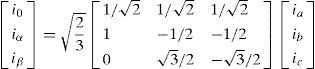
2P-Q Control StrategyConventional control strategy for active power filters is based on p-q theory which is called IRP (instantaneous reactive power) theory. This control scheme is used to detect and compensate undesirable powers. To achieve this goal active and reactive powers are calculated in time domain and presented in a coordinate frame in which power components are obvious. Clarke Transform of voltages and currents specified in phase a, b and c coordinates, as shown in figure 1, into quantities in orthogonal ¿, ¿ and 0 coordinates can help us to achieve this goal.

Clarke Transformation of three-phase voltages and currents has the form below.
and consequently, instantaneous active and reactive power of such a system are equal to: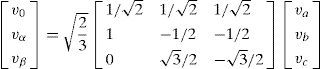
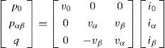
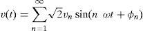
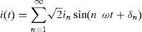
Active power is presented in two separate zero and summation of positive and negative consequence modes. If the voltage and current of such a load has the form (4) and (5) respectively:
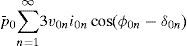
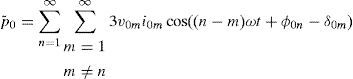
According to the previous equations we can represent the active and reactive powers as:
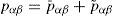
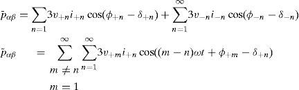
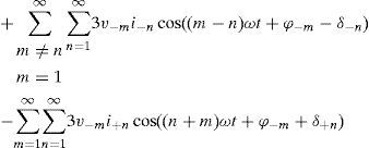


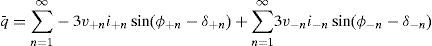
When we have harmonic distorted or imbalanced loads in the grid, alternative component of active and reactive powers appear.
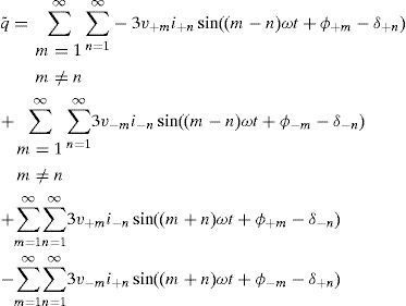
Undesirable powers shown in equations (8) to (14) should be compensated.
To identify the positive sequence of fundamental component of voltage and current, PLL (phase locked loop) and PSD (positive sequence detector) tools are used to obtain the fundamental frequency and amplitude of the main signal.
For active filters there are two different compensation strategies; “Constant supply power” and “sinusoidal supply current”. Second one can help us to achieve our purpose to reduce the load and supply current THD; Block diagram of this control method is shown in figure 2.

As it can be seen from figure 2, power components that are candidates to be compensated are negative and alternative components of Pa¿¿ and the whole amount of reactive power. After operation of the control process, the outputs of system are reference currents that should be applied as a signal to the inverter switches.
After calculation of reference currents by sinusoidal current strategy, we should control DG's current in the reference current range. The hysteresis control method can help us to achieve this goal. We determine an appropriate hysteresis band for the current tolerance in this control method. As it can be seen from figure 3, if DG's current passes the determined band, control system send the gate signal to the inverter switches to increase or decrease the current.

Switching frequency depends on current changing rate from the lower side to the upper side band or viceversa. By adjusting the hysteresis band as a small value the output current of DG will have close shape to the reference signal but it increases switching frequency and losses and causes EMI effect.
When the load is unbalanced, active and reactive powers are time variant and do not provide exact information on power properties of the grid. An additional analysis is required to determine active, reactive and unbalanced powers.
Time-domain based IRP theory has no advantages over the frequency-domain approach with respect to the time period needed for identification the exact value of power properties of the grid loads.
DG designation as an active power filter, based on p-q control strategy can be extended to compensate unbalanced nonlinear load currents, even when the source voltage and current are unbalanced and distorted, like the microgrid that is shown in figure 4.

There are three harmonic detection methods which play an important role in control strategy of the active filter [24]:
- 1)
Load current detection: This method detects load current, which flows downstream of the point of location and extracts harmonic current from load current.
- 2)
Source current detection: This method detects supply current, which flows upstream of the point of location and extracts harmonic current from source current.
- 3)
Voltage detection: This method detects bus voltage at the point of location and then extracts harmonic voltage.
Droop control has been widely used in microgrids in order to share the demand power. This control method mimics the governer and exciter of a synchronous generator and regulates output frequency and voltage of the generator according to the active and reactive power derived from it's terminal.
Droop control method considered in this paper contains inner voltage and current controllers rejecting disturbances.
Proposed control strategy is conducted in dq0 frame which facilitates control process by transforming the voltage and current variables in three phase (abc) frame which are time variant quantities to the proposed frame. In dq0 frame control variable are time invariant (dc) quantities. Figure 5 shows dq0 and abc frames. Transformation equation and reverse equation are shown in (15) and (16) and ¿ is defined in (17). In (17), ¿ is time variant angular velocity and ¿0 is initial phase angle.
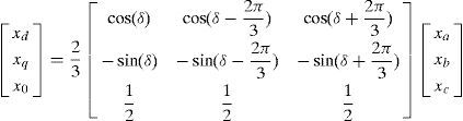
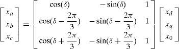
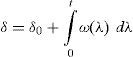

Figure 6 shows power, voltage and current controllers, output LC filter and coupling inductance of a DG unit in a microgrid, by this assumption that the input of DG inverter is ideal dc link [25–27].
3.1Power controller
According to the voltage and current quantities in dq0 frame, instantaneous amount of powers can be calculated as follows:
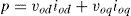
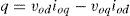
To derive active and reactive powers, the above quantities should be passed through the low pass filters with ¿c as cut-out frequency.


Considering the droop characteristic, reference voltage and frequency of power controller can be obtained as follows:
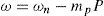
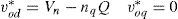
In the above equations ¿n and Vn are nominal amounts of frequency and voltage of microgrid and mp and nq are droop gains. These gains relates to some economic and technical features of a generator but are assumed same for all the generators in this paper for simplicity. Figure 7 summarize power controller.
3.2Voltage and current controller
Reference voltage and frequency produced by power controller are sent to the voltage controller and outputs of this controller are sent to the current controller. Both controllers are shown below (figure 8 and 9).


Inner PI controller guarantees zero difference signal of real and reference quantities steady state error and improve system transient response. Also feed-forward loops isolate generators from load disturbances and enhance system power quality in presence of harmonic distorted loads.
4Simulation ResultsPerformance of discussed control strategies is examined in this section. First IRP theory control is considered for a DG near the harmonic distorted load, operating as a shunt active filter. The analysed circuit schema is shown in the Figure 4. Nonlinear load is a resistor connected to the output of a three phase full bridge rectifier. There is an LC filter in the output of the generator to eliminate switching high order frequencies.
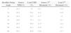
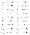
Parameters of the simulated system in PSCAD are shown in table 1. To create different harmonic distortion levels in the load, rectifier thyristor firing angle is tunable. Six harmonic levels are tested and the results are shown.
Figure 10 and 11 show source, load and DG currents for 10 and 60 degrees rectifier firing angles respectively.
source b)load c)DG currents.")
source b)load c)DG currents.")
source b)load c)DG currents.")
As it can be seen, harmonic distortion in the load and source current in the 60 degrees mode is higher than 10 degrees mode.
Third harmonic percent is chosen among the harmonic components spectrum of the source and load current. The exact amount of six harmonic distortion levels applied to the load with the system response is also shown in table 2.
Grid with p-q control Response To Load Harmonic Distortion.
| Rectifier Firing Angle | Source THD(%) | Load THD (%) | Source 3rd Harmonic (%) | Load 3rd Harmonic (%) |
|---|---|---|---|---|
| 0 | 28.3 | 33 | 12.1 | 11.8 |
| 10 | 28.4 | 34.1 | 11.8 | 11.9 |
| 20 | 28.3 | 35.7 | 11.7 | 12 |
| 30 | 28.8 | 37.3 | 12.1 | 12.1 |
| 40 | 28.3 | 39.5 | 11.9 | 12.4 |
| 50 | 28.4 | 41.3 | 12.6 | 13.1 |
| 60 | 28.7 | 44.8 | 13.6 | 13.7 |
Second simulation is made in MATLAB Simulink to evaluate the proposed droop control in the presence of nonlinear load.
One phase schematic of microgrid and system parameters are shown in figure 12 and table 3 respectively.

Figure 13 shows the load current and it's THD and 3rd harmonic and figure 14 and 15 show the effect of harmonic distorted load in the source (DG1) and other load (load 2) side. It can be seen that in presence of the proposed controller, harmonic distortion is reduced obviously in comparison with the traditional p-q control.


In detail important drawback of the IRP theory is the inability of this control method to reduce the amount of THD with respect to the proposed droop control and also to maintain the source current THD and third harmonic percent in constant¬ value when increasing the load harmonic distortion.
The main causes of this drawback for IRP control strategy are:
- 1)
The high pass filter separating alternative value of the active power P¿¿ has a fixed crossing frequency. By increasing load harmonic distortion, the amplitude of the all harmonic components in the active power increases including sub-harmonics. By deleting all high frequency components (for example higher than 20Hz in figure 2), remained sub-harmonics can generate voltage and/or current internal or main harmonic components considering active power formula in (7) and (8).
- 2)
In p-q control strategy load imbalance that affects source current asymmetry and associated unbalanced power (D) is missed:
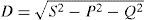
Compensating the unbalanced power reduces harmonic components (especially 3rd harmonic) that are influenced by asymmetry and load imbalance. By ignoring this power component in compensation as we can see in IRP theory, we have higher THD in currents of the grid. As a result, DGs operating as an active filter controlled by IRP theory does not eliminate all harmonics and cause high THD.
By demonstrating the traditional sinusoidal source current control strategy based on IRP theory, it was concluded that ignoring the distortion power (D) in compensating process and also sub-harmonics of Pep crossing from the controller interior high pass filter cause the presence of some harmonic components and high THD.
Proposed control scheme have the capability of sharing load active and reactive powers among all the generators in a microgrid as well as compensating harmonic distortion generated by nonlinear loads.
In order to conclude the generality of the proposed method, two different loads are also concluded in the case study. Resistive load with step change and induction motor in fault condition are two sample of loads added to the simulation of the microgrid.
First, step change in active power is considered as it can be shown in Figure 16. All the active power requested by network and loads is 12kW before the demand change. After 1 second 9kW of total P is increased by controlled current source.

Figure 17 shows active powers generated by DGs in each three buses. DGs produce equal P in steady state time because droop gains of w-P characteristics have the same value. This figure shows that the proposed controller maintains grid stability after step change in demand power.

In order to study dynamic loads in the microgrid with proposed droop controller, induction motor as the most common industrial load is tested in fault condition. Two 7.5kW motors are in buses 1 and 3.
Single phase schematic of the circuit is shown in Figure 18.

After 0.6 seconds of motor starting a two phases to ground fault is occurred in bus1. After 3 cycles the fault is cleared. Figure 19 shows stator current of the motor in bus 1. It can be seen that the controller has the capability of maintaining system stability during and after fault clearance.

It is concluded that in different types of load, proposed controller has the satisfying performance.
5ConclusionIn this paper the response of a microgrid to the interfaced harmonic distorted load was analysed. A new control algorithm to mitigate harmonic distortion was considered for distributed generators (DGs) and the effect of this control scheme was shown in the currents of DGs and other loads.
The proposed control algorithm was compared with the conventional control strategy for harmonic distorted loads that is sinusoidal source current strategy based on the instantaneous reactive power theory. PSCAD simulation results for IRP theory control had high total harmonic distortion (THD) and 3rd harmonic percent. In comparison inner voltage and current controllers of the proposed control scheme with their disturbance rejection capability, mitigated THD and 3rd harmonic percent and MATLAB simulation results confirmed this.
The generality of the proposed method was also examined in presence of different loads such as step change of demand power and induction motor in fault condition.