


We report the development of an ultrasonic levitation system. Liquid drops or solid samples of diameter less than one half wavelength of the excitation frequency are levitated without contact just below the pressure nodes. The piezo transducer is excited by an ultrasonic signal of around 29kHz through a voltage amplifier. The choice of the number of half-waves of the acoustic field in the space between the reflector and radiator is made by means of a micrometer. A lamp, an amplifier and a frequency generator are integrated to the levitator. The diameters of the droplets of liquid that can levitate are of the order of tenths of mm to 3 or 4mm, depending on the liquid properties (density, surface tension, etc.). Solid objects can also be levitated. The maximum voltage of the system is 20Vrms.
Se presenta el desarrollo de un sistema de levitación acústica ultrasónica. Gotas líquidas o muestras sólidas de diámetro inferior a media longitud de onda a la frecuencia de excitación levitan sin contacto justo por debajo de los nodos de presión. El transductor piezoeléctrico es excitado por una señal ultrasónica de aproximadamente 29kHz a través de un amplificador de voltaje. La elección del número de semilongitudes de onda del campo acústico en el espacio entre el reflector y el radiador se hace por medio de un micrómetro.
Una lámpara, un amplificador y un generador de frecuencia están integrados al levitador. Los diámetros de las gotitas de líquido que se pueden levitar son del orden de décimas de mm a 3 ó 4mm, dependiendo de las propiedades del líquido (densidad, tensión superficial, etc.). Se pueden levitar también objetos sólidos. El voltaje máximo del sistema es de 20Vrms.
The acoustic levitation is a process by which an object is suspended in a stable position against gravity, without apparent physical contact by means of the acoustic radiation force. An acoustic wave exerts a force on any object immersed in the acoustic field. Normally these forces are weak, but if large acoustic intensities are used the force may be significant enough to levitate small objects. The force that is involved is called acoustic radiation pressure a nonlinear effect studied first by Rayleigh [1]. This radiation pressure varies with frequency and is zero in the first approximation. It requires a second order approximation for a nonzero mean pressure which is very small compared to the sound pressure. This effect is mainly a consequence of the nonlinearity of the adiabatic compression law of the gas implied by the equation of state [2, 3]. Chu et al [2], calculated the forces of a plane wave on a surface perpendicular to the direction of incidence, and found that it only depends on the distance to the plane and the density of acoustic energy, radiation pressure is the average pressure acting on the object surface. The levitation force is ultimately the integrated radiation force on the object's surface. The Kundt's tube experiment, dating from 1886, is one example of the levitation effect, wherein the dust particles are concentrated in the pressure nodes of the standing wave generated in the tube. In 1933, Bücks & Müller [4] presented an acoustic levitation system consisting of a radiator and a reflector, a small particle is positioned close to the pressure nodes. In this case, a standing wave is generated between the radiator and the reflector with a number of pressure-nodes depending on distance between them. In this case the suspension is caused by the axial pressure of the standing wave radiation. Objects, solids or liquids can levitate under the pressure nodes. The first detailed study of levitation by stationary waves was due to King [3]. G'orkov [5] presented a simple method to calculate the forces acting on an arbitrary field using the velocity potential represented as a sum of incident and scattered fields. Xie &Wei [6] studied the levitation of disks and the dynamics of water drops in stationary plane waves, solving the problem of dispersion through the use of finite elements. The construction of stationary wave acoustic levitators also has an extensive recent literature. Otsuka [7] used a circular plate as an ultrasonic radiator which produced very high pressures by exciting the flexural vibration mode with two circular nodes. In 2001, Xie &Wei [6], levitated tungsten spheres. Trinh [8] presented a compact acoustic levitation system for the study of fluids. In this work, we report the construction and evaluation of an ultrasonic levitator at a working frequency of around 29kHz.
2Description of the systemThe core of the ultrasonic levitator is a high-displacement actuator comprising a bolt clamped Langevin transducer (Steminc, Steiner & Martins, SMBLTD45F28H, resonance frequency of 28kHz) and a post that functions as an ultrasonic displacement amplifier. Bangviwat [9], discusses the performance of piezoelectric drivers that use stepped horns. In these designs the ultrasonic transducer is sandwiched between metal sections, normally aluminum or steel- the so-called Langevin transducer. The backing piece is usually a quarter wavelength long, while the front piece is a stepped horn as suggested by Mason, in 1942. Such a configuration is often referred to as a Mason horn, in this horn the final radiating surface is of greater diameter than the radiating section of the transducer and in the last decades the radiating surface used has been indeed a metal disk, Mason made a detailed analysis of such a configuration using variable length sections lr (radiating section) and lf (front section), the best configuration is that in which lf and lr are each one quarter wavelength long, as depicted in Figure 1. In the last decades a so-called half-wavelength configuration has been used in which the lf section is half a wavelength long and the radiating section a quarter wavelength long, we used such a configuration and found it to be of lesser efficiency than a quarter wavelength levitator.
 is connected to a metal post, the radiating section (lr), forming an impedance converting stepped horn. The final section of the radiating section would be the radiating disk, not shown")
The Mason horn transducer is made of a Langevin transducer -two piezo disks sandwiched between two metal pieces, sometimes the back-piece is made of steel and is of lesser length than the front section. The front section (lf) is connected to a metal post, the radiating section (lr), forming an impedance converting stepped horn. The final section of the radiating section would be the radiating disk, not shown
The designed displacement or velocity amplifier consists of an aluminum bar (radiating section) of circular cross section of 6mm in diameter and length lr=43.8mm. The amplification at the free end is theoretically equal to the ratio of the sectional areas of the transducer transformer and, in this case with a value of nearly 49. The end of the radiating section bar has an aluminum disk, 25mm in diameter and 2.2mm in thickness. This disk constitutes the acoustic field radiator, vibrating in a flexural mode with one circular node, excited at the center at a resonance frequency near to the transducer's resonance. It is the single most important element in providing the modal ultrasonic radiation field. The radiating section length plus the disk thickness is equal to one quarter of the wavelength of the sound as given by the resonance frequency (electrical) of the Langevin transducer and the length of the its front section (lf=45mm).
Opposite to this disk is a reflector which can be flat or concave and is fitted with a micrometer head aligned with the axis of the disk. As a result of the multiple reflections between the radiator and the reflector a stationary acoustic field is established of wavelength (in the air) of approximately 12mm. By moving the reflector the maximum pressure can be seen on an oscilloscope using the microphone signal amplifier in the levitator. Several half-wavelengths can be established in the space between emitter and reflector, the levitation points will be below the pressure nodes. The concave reflector was selected for further experiments. Two concave reflectors were made, following [6], with radius of curvature of 1.22λ and 2λ, respectively. The operating and technical characteristics of the levitator, are described in what follows.
2.1Disk thicknessThe main element of radiation that gives the standing acoustic field in the levitator is the radiating disk. The diameter of the disks reported in the literature range from approximately 25.4mm to 50mm in diameter. We tried several diameters and the one that gave best results was a 25mm in diameter. In order to test for the best thickness of this disk the measured resonance frequency, excited by the radiating section at the center, corresponding to the flexural mode with one circular node, was compared to the frequency predicted by Blevins [12]. The calculated frequency should in principle be close to the one of the transducer plus horn - somewhere around 29kHz. The formulas given in [12] don't give a good approximation to the measured frequency. A series of disks of several thicknesses -between 1–3mm- were made, and the resonance frequencies corresponding to a mode of vibration with a nodal ring were measured in the complete system. The resonance frequencies of the complete (transducer plus radiating section plus disk) levitator are graphed versus the cubed thickness, as shown in Figure 2.
 of a metal disk versus corresponding resonance frequency, when it is screwed to the radiating section of the levitator. The resonance frequency closer to the resonance of the transducer plus radiating section is around 29kHz")
As can be seen in the graph, the thickness of a disk for a resonance frequency of around 26–30kHz, should be around 1.8mm to 2.2mm. Actually the transducer with the stepped horn plus disk added constitutes a complex mechanical system that has at least two-coupled-resonances. These resonances are further explored in what follows.
3Measurement of the levitator resonancesIn order to explore the resonances of the single transducer and the transducer with post (radiating section) and disk added, in the zone around 26–30kHz, the corresponding admittance: transducer alone, transducer with aluminum post, and transducer with post and disk -of various thicknesses- was measured, for each case. The sound pressure emitted at 25mm from the disk - when vibrating with one nodal circle- was measured for each disk. The instrumentation used comprised a digital Lock-In amplifier SRS SR850, a measurement microphone ¼" B&K 4135, a microphone voltage source B&K 2807 and a voltage amplifier Systems Lab A-303.
The configuration used for the admittance measurement is shown in Figure 3(a), the common procedure for electrical admittance measurement was followed [10] -that is measuring the voltage across a resistance connected in series with the Langevin transducer or the complete system- the resistance value in our case was 100Ω. The instrumentation used in the corresponding sound pressure measurement configuration is shown in Figure 3(b).
 The electrical admittance measurement configuration: the Lock-In amplifier provides the sweep excitation signal, the electrical admittance corresponds to the voltage measured across the resistance R. (b) The SPL measurement configuration")
The measurement of the admittance was performed as follows: a) the transducer was placed on a cushion of polyurethane to avoid spurious vibrations. b) a frequency sweep was generated in the Lock-In amplifier in a selected frequency range that included the expected transducer resonant frequency (∼28kHz), the signal was fed to a voltage amplifier, which in turn was connected to the transducer via a 100 Ω resistance. The voltage input to the transducer was 1.36Vrms, the response signal constitutes the input signal to the Lock-In amplifier. It was measured across the resistance. With the same experimental arrangement, the aluminum bar (transformer) and an aluminum disk were screwed to the transducer and the same measurement repeated.
transducer, transducer plus aluminum post, transducer plus aluminum post plus disk, and the same procedure for 4 disks between 1.5–2.5mm in thickness. The resulting graph is shown in Figure 4(a), only the result for two disk thicknesses: 1.85mm and 2.2mm, are shown.
 The electrical admittance of: the transducer, black line; the transducer + metal post (radiating section), blue; transducer + post + metal disk, cian and magenta; the half-wave configuration plus disk; green. (b) The sound pressure level response at 25mm above the radiating disk. The colors of the graphs for the configurations agree with those corresponding to (a). The amplitude of the excitation signal -a frequency sweep-was 3.0Vrms")
(a) The electrical admittance of: the transducer, black line; the transducer + metal post (radiating section), blue; transducer + post + metal disk, cian and magenta; the half-wave configuration plus disk; green. (b) The sound pressure level response at 25mm above the radiating disk. The colors of the graphs for the configurations agree with those corresponding to (a). The amplitude of the excitation signal -a frequency sweep-was 3.0Vrms
Clearly the mechanical effect of the added mass is shown in the admittance curve. Now there are two resonances and two anti-resonances. The results clearly show that: there is only one resonance when the transducer is alone, when the post is added a new resonance appears at a higher frequency, and when the disk is added those two resonances move and get closer between them.
The thickness of the disk is a very sensitive parameter for the resulting resonance frequencies, as clearly shown by the graphs for disks that only differ by 0.1mm in thickness. The fact that there are two coupled resonances introduces a problem -as hard as it is tried to make the thickness of the disk such that the resonance coincides with the transducer plus post resonance the two resonances never coincide. The best thickness, without introducing extra damping or other artifacts -is the one that makes the two resonances to have nearly the same amplitude, which occurs when both resonances differ in frequency the least. Depicted in Figure 4(b), is the result for the half wavelength levitator -green line- using the same metal disk of 2.2mm in thickness as used in the quarter wavelength horn. The main result for this case is that the amplitudes of the electrical resonances are lower in amplitude for the same disk than the one corresponding to the quarter-wave horn, as before the frequencies does not coincide with the one corresponding to the transducer alone.
The sound pressure level of the radiated acoustic field for the disks of 1.85, 2.1 and 2.2mm in thickness was measured at 25mm above the disk, on the disk axis. The results for the 1.85 and 2.1mm are shown in Figure 4(b). The results also show that the quarter wavelength levitator is more efficient than the half wavelength horn levitator, the SPL is 10dB lower than the former at the frequency of the clearest formed resonance -green line. For all disks the measured SPL was lower than for the quarter wavelength case. In all the cases the frequency was such that the resonance of the disk was that corresponding to the one nodal circle resonance, when the pressure achieves a maximum level, the nodal ring formed is shown in Figure 5.

Finally considering the results for the SPL measurements it was decided to use the disk with best results, which is the one with 2.1mm in thickness. This apparent problem has the advantage that one can choose the frequency that best fits the electronics used, and still have the same amplitude in the SPL emitted. The transducer was held with an O-ring located near the piezo disks.
4Vibration profileThe vibration profile measurement was performed with the measurement arrangement shown in Figure 6.

The measurement method, based on the amplitudes of the harmonics in terms of Bessel functions, is basically the same reported by the authors elsewhere [11], and will not be described in this work. The measurement arrangement comprises a differential optical Doppler system for measuring longitudinal vibration, mounted on a square steel plate of 50cm side and 1.9cm in thickness supported on four polyurethane mattresses, somehow as an anti-vibration table. A function generator SRS DS345, a current preamplifier low noise SRS SR570, a spectrum analyzer Tektronix 2712 and a high voltage amplifier Systems Lab A-303 were used. The optical system consists basically of a laser diode, a prism beam splitter and a photodiode, as shown in the diagram in Figure 7.

The purpose of measuring the longitudinal vibration levitator core is to obtain the profile and magnitude of the vibration amplitude along the latter, which is the essential part of the levitator. To do the measurement we proceeded as follows: (1) the generator supplied to the voltage amplifier, a sinusoidal signal of 29,530Hz and 0.035Vpp so that at the output thereof, with the core connected, obtained a voltage of approximately 0.35Vrms measured with True rms multimeter Tektronix DMM914. (2) with the optical system the reflected laser light was recorded, connecting the photodiode to the current preamplifier the sensitivity was adjusted so that the amplitude of the signal could be measured with the spectrum analyzer. (3) the selected measuring points were marked along the core with a spacing of 1cm. (4) by relocating the optical system at each measurement point the crossing position of the laser beams was relocated, making small movements to zoom in, zoom out, raised and lowered in order to obtain in the analyzer the maximum amplitude of the fundamental (J1) frequency, and the harmonics (J2, J3, …) as small as possible or masked by the background noise in the analyzer. e) At each measuring point a certain time elapsed in order to stabilize the amplitude until a variation of no more than 10% between the maximum and minimum was observed in the analyzer for the average of 16 spectra.
4.2Stability test of the systemTo make a measurement of the vibration amplitude the measuring system was tested for stability in time in the following manner: a) the optical system is placed in a position in which the signal obtained was very stable and 16 spectra were averaged, obtaining an amplitude of 2mVrms. b) The amplitude of the signal generator was increased to reach the maximum amplitude observed in the analyzer, once located the 16 spectra were averaged to obtain an amplitude of 22mVrms. c) The initial amplitude in the generator was set and 16 spectra were averaged, obtaining the same amplitude as in a), which proved the stability of the system. This procedure was repeated three times during the measurement.
4.3ResultsThe results of the amplitude measurements are shown in the graph in Figure 8.
 along the levitator, from the zone near the piezoceramic rings, to the radiating disk (•). Solid lines are fit to the measuring points, the dotted line is indicative that there is a jump in amplitude, due to the effect of transformer, along the metal post")
The results of the measurement of the voltage amplitudes of J1, provide the absolute amplitudes of the longitudinal vibration through the arguments of the Bessel function in terms of the angle of intersection of the beams and the wavelength of the laser [11].
5ElectronicsThe signal of ultrasonic frequency is produced by a function generator comprising as main element an integrated circuit ICL8038C which is a precision waveform generator configured to generate a sine wave in the range of frequencies between 25 and 35kHz, this frequency should be adjusted to the resonance frequency of the nucleus of the levitator (about 30,500Hz) to operate with maximum efficiency in order to levitate with less operating voltage. The integrated circuit used has a frequency variation of 250ppm/°C, so that the resonance frequency in question once stabilized, has a variation of about ± 10Hz/°C. Tests confirmed the correct operation of the levitator. The sinusoidal signal is supplied to a preamplifier designed and constructed with the integrated circuit TL071, in order to control the amplitude of the input signal to the power amplifier; it is based on the integrated circuit LM3886, its main features being a low heat generation and high output stability. The highest voltage attainable was 19.6V rms. Figure 9 shows a block diagram of the complete system.
6Levitation force and measurements results
The average acoustic force exerted on a sphere in a stationary acoustic sound field is given by Crum [13], for the general case; for a rigid sphere a slightly different formula obtains as given in Eq. 1:
where V0 is the volume of the sphere, P the sound pressure amplitude, kz=2π / λz and λz is the wavelength along the z axis, δ the ratio of density of the sphere to that of air, c* the sound speed in the material of the sphere, c sound speed in air, and σ = c*/c. The first term in brackets is due to the compressibility of the sphere, the second term is the result for an incompressible sphere, or rigid sphere. For this case one obtains Eq. 2: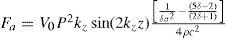
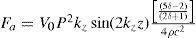
A sphere can be trapped in a given position if the acoustic force balances the vector sum of the buoyant force (Vogρ) of the air on the sphere of density ρ*, and the gravitational (Vogρ*) force on it, with g being the gravitational acceleration. Crum states that it is possible to choose a value of pressure readily measurable that traps the sphere at a position z = λz/8 above the radiator which occurs when the maximum of sin(2kz) is equal to 1. This pressure is then a minimum trapping pressure, which is given by [13] as depicted in Eq. (3),
It is interesting to note that this expression for the minimum trapping pressure does not involves the sphere radius; this is due to the fact that the acoustic, the buoyant, and the gravitational forces are all proportional to the volume of the sphere [13].
In terrestrial conditions the particle is positioned below the pressure node of the standing wave. The ultrasonic wave, moreover, is not a perfect plane wave but has a certain divergence, so that there are radial components of the air particle velocity resulting in a radial force which tends to center the particle in certain positions that are sites of minimal acoustic potential. The easiest reflector to use was the one of 2λ of radius of curvature, as the great concavity of the other reflector (1.22λ) hindered the observation of the suspended particles, due to the lower angle of vision between the disk and the edge of the reflector which has a greater thickness.
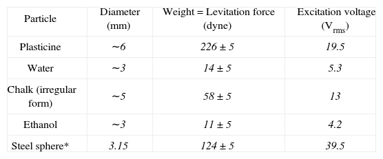
The results obtained for a range of different particles is shown in Table1. When the excitation voltage has an amplitude of nearly 40Vrms the system can levitate a sphere of steel 3.2mm in diameter; this was done with the aid of an external high-voltage amplifier, not with the prototype circuit, which has a maximum voltage output of 20Vrms. Figure 10, shows a photograph of a levitated steel sphere of that diameter.
Diameters and weights of levitated particles, the force (vertical) acting in each case is equal to the weight of the particle.* levitated with the aid of an external high voltage amplifier, not the one of the prototype
| Particle | Diameter (mm) | Weight = Levitation force (dyne) | Excitation voltage (Vrms) |
| Plasticine | ∼6 | 226±5 | 19.5 |
| Water | ∼3 | 14±5 | 5.3 |
| Chalk (irregular form) | ∼5 | 58±5 | 13 |
| Ethanol | ∼3 | 11±5 | 4.2 |
| Steel sphere* | 3.15 | 124±5 | 39.5 |

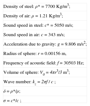
The acoustic force acting on the steel sphere -the only one whose radius and mass could be readily measured-, using common values of densities, sound speed, etc., was calculated by substituting the minimum pressure calculated with Eq. 3, in Eq. 2. The values used are shown in Table 2.
Physical parameters and formulas used in the calculation of the acoustic levitation force and pressure acting on a metal (steel) sphere
| Density of steel: ρ* = 7700Kg/m3; |
| Density of air: ρ = 1.21Kg/m3; |
| Sound speed in steel: c* = 5050m/s; |
| Sound speed in air: c = 343m/s; |
| Acceleration due to gravity: g = 9.806m/s2; |
| Radius of sphere: r = 0.00156m, |
| Frequency of acoustic field: f = 30503Hz; |
| Volume of sphere: V0=4πr3/3 m3; |
| Wave number: kz=2πf / c ; |
| δ=ρ*/ρ; |
| σ=c*/c ; |
The calculation of the resulting force gave a value of Fa = 123.4 dynes; a value very similar to the one given by the weight (123.9 dynes). The minimum sound pressure level (SPL) calculated was 168.8dB re20μPa, the approximate, minimum SPL was measured with a 1/8″ microphone (G.R.A.S. type 26AC7/Power module type 12AA) at several points near the levitation point of the steel sphere. An average SPL value (for four points) of Pm=164 dB re20μPa was obtained, which is four to five decibels lower than the calculated value.
The presence of the microphone, which has dimensions of the order of the wavelength of the sound, distorts and scatters the field. The measured pressure would tend to be lower than the real pressure acting on the sphere in the same location. Nevertheless, the measured and calculated values, of both the acoustic force and the minimum sound pressure level, agree reasonably well with the theory given by Crum [13]. It is to be noted, that it can happen that a particle with low density and relatively large volume can have a greater mass than a smaller particle but greater density, and still levitate with a lower amplitude of the excitation voltage (as was the case for the spheres of plasticine and steel, in Table 1).
7ConclusionsWe have built a prototype of ultrasonic levitator (from a commercial Langevin transducer) with mechanical and electronic components relatively easy to machine or acquire respectively. With the design of a mechanical amplifier of relatively small dimensions the resonance frequency of the core almost did not alter that of the transducer. The levitation standing wave is established between a disk (of 2.5cm in diameter and 2.1mm in thickness) and a concave reflector, and is adjusted with the aid of a micrometer screw. Levitation of liquid drops (such as water, ethanol, etc.) and solid spheres particles. The heaviest particles had a mass of the order of 500mg, with relatively small driving voltages on the range of 1–20Vrms, the highest voltage that the prototype was capable off. The measured and calculated values of minimum pressure and acoustic force agree remarkably well with the theory. The particles can remain levitated during periods of several hours.