


The present work explores the strength enhancement via minor modifications of the pattern design in pure light SiC woodpile structures created by filament printing. In particular, the effect of the filament stacking angle on both the compression resistance and the elastic modulus of these structures are evaluated. Different patterns were designed while maintaining the bulk structure density, therefore the differences in the mechanical data (strength and elastic modulus) are not attributable to density variations. All of these materials were partially sintered at intermediate temperature for additional porosity enhancement. Moreover, SiC specimens made by full filament overlapping were produced to serve as reference massive material. Remarkably, the massive SiC printed material displays ordered spherical porosity and a closed-pore foam appearance, thus revealing a novel route for producing these type of porosity. Results evidence that the structure robustness can be tuned through slight design modification, which thus offers the possibility of further structure lightening without reducing the target strength.
El presente trabajo explora la mejora de la resistencia mecánica de estructuras ligeras formadas por apilamiento de rodillos de SiC puro, procesadas por impresión directa de tinta, a través de modificaciones menores del patrón de diseño. En particular, se evalúa el efecto del ángulo de apilamiento de los filamentos sobre la resistencia a la compresión y el módulo elástico de estas estructuras. Los diferentes patrones fueron diseñados manteniendo similares densidades aparentes de las estructuras, por lo tanto, las diferencias observadas en los resultados mecánicos (resistencia y módulo elástico) no son atribuibles a variaciones de densidad. Todas las estructuras se sinterizaron parcialmente para mantener una elevada porosidad. Además, se produjeron muestras de SiC macizas creadas por la superposición de filamentos utilizadas como material masivo de referencia. Curiosamente, este material muestra una porosidad esférica y ordenada, y presenta la apariencia típica de esponjas con porosidad cerrada, mostrando en consecuencia una ruta alternativa para la fabricación de este tipo de materiales celulares. Dado que la robustez de estructuras 3D se puede maximizar a través de una ligera modificación del diseño, esto permitiría alternativamente aligerar aún más las estructuras sin perjudicar su resistencia.
Porous ceramic materials are essential for a wide number of challenging applications that demand low specific mass and unique thermal or chemical properties, as for instance, hot gas filters [1,2], membrane and catalyst supports [3] or devices for energy storage and conversion [4,5]. Their impact also reaches other areas such as the biomedical, especially for bone tissue engineering [6–8]. For many of these applications, the occurrence of certain hierarchical porosity results in a comparative advantage [9–11]. In any case, certain mechanical requirements must be met. Accordingly, simple design modifications that would allow further adjustment of other characteristics, such as specific mass reduction or porosity size increase, without compromising robustness would be valuable in many of those applications.
Among the current methods to produce highly porous ceramic materials, foam fabrication seems the most frequent choice, and works often look for the enhancement of their mechanical performance [12,13]. In fact, some structure modifications have been explored with the aim of increasing their compressive strength. For example, freeze-cast foams devised by Fukushima et al. took advantage of the microstructural anisotropy produced by the unidirectional ice front, hence increasing their compressive strength when tested along the freezing direction [14]. In this sense, additive manufacturing (AM) techniques offer a much more controlled design approach for optimization of any property [15]. Along this line, the present work studies the effect of slight design variations on the mechanical properties of woodpile type structures developed by direct ink writing (DIW). A control of the external shape as well as of the internal structure is possible by doing simple geometrical alterations on the filament stacking pattern defined by the computer design software. Owing to these advantages, there is some room for improving the robustness, and simultaneously other characteristics of the structures, thus geometrical density becomes a reasonably adaptable property. Silicon carbide (SiC) has been selected as the model ceramic material for this study owing to its comparative importance in the above mentioned areas.
Although the outcome of new techniques has shown the possibility of “free” 3D deposition without spatial restrictions, i.e. no limits in any direction [16–18], commonly filament printing methods consist on simple layer-by-layer superposition. As a result, the contact points between consecutive layers are frequently aligned, like columns perpendicularly oriented to the layer plane, i.e. along the Z-axis (Fig. 1a). Commonly, mechanical properties of these kinds of 3D-architectures are evaluated by compression tests along the Z-axis (Fig. 1a) and these mechanical data are determined not only by the porosity specifications, but more precisely by the number of pillars sustained by the nodal points. Moreover, the effect of a customary frame encasing the structure is often overlooked on the evaluated strength.
 and compression test schema with axis orientation reference (b).")
Actually, the number of columns is closely related to the geometrical density (ρ) as increasing the number of the contact points per unit volume reduces the macro-porosity of the architectures, rising ρ. In the same way, increasing frame thickness would produce a similar effect. Therefore, a more sensible approach to assess the true influence of the porosity shape on the mechanical properties of this type of scaffold would be achieved by previously removing two opposite side walls of this architecture and then testing it under compression along the axis defined by the free-sides (see Fig. 1b). In order to determine the effect of the porosity shape in the mechanical properties of cellular ceramics, corresponding sets of 3D structures with slightly different macro-porosity patterns have been produced by filament printing and partial sintering methods, and then tested taking into account the aforementioned considerations.
Experimental procedureStructure designsThe regular design is formed by overlaying rod layers that successively cross at 0° and 90° (referred to the x-axis, as in Fig. 1a). The following designs are precise modification of this initial pattern, attained just by changing the orientation of the rods (θ angle) in 15° steps starting from 45°, and accordingly labelled as 45°, 60° and 75° and regular samples, as depicted in Fig. 2a. Equal bulk density in the different designs (45°, 60°, 75° and regular) was assured by keeping the sum of the lengths of rods composing the structure constant for each scaffold, while maintaining the external dimensions. Dimensions of the CAD models (RoboCAD4.0, 3-D Inks LLC; Stillwater, UK) were 9.5mm×9.5mm×3.4mm, except for the 45° structure, for which a longer lattice along the X-direction was designed, specifically of 18.5mm×9.5mm×3.4mm, in order to assure some complete rods connecting the top and bottom of the structure.
. Bulk CAD models (b and c, respectively).")
In addition, a reference SiC massive material was processed by filament printing, and two types of bulk shapes were designed and printed; a parallelepiped with dimensions similar to the outer geometry of the patterned structures (named as bulk sample, Fig. 2b); and a prismatic bar (referred as bending sample, Fig. 2c) with CAD model dimensions of 25.0mm×5.0mm×3.0mm Both designs were built by filling the space via rod overlapping patterns. Rod spacings of d/1.1 between the centre of consecutive rods into same layer and of d/1.27 between consecutive layers were selected, where d is the CAD model rod diameter (similar to the nozzle tip diameter), similar to Feilden et al. designs [19].
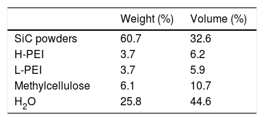
Material processingA detailed description of ink preparation for this SiC material is precisely detailed in previous works [20,21]; briefly, the ceramic ink was produced using fine SiC powders (β-SiC powders of average size d50=50nm, polytype 3C; NanoAmor, USA) and different organic additives that were dispersed and homogenized in distilled water, using a planetary centrifugal mixer (AR-250; Thinky Company, USA). High molecular weight polyethylenimine (H-PEI, Mw=25,000gmol−1, 99wt.% concentration; Aldrich Chemical Co., USA) and low molecular weight polyethylenimine (L-PEI, Mw=2000gmol−1, 50wt.% concentration; Aldrich Chemical Co., USA) were used as dispersant agents, and methylcellulose (Methocel F4M, Mw=3500gmol−1, 5wt.% concentration; Dow Chemical Company, USA) as viscosifier. The final ink composition is detailed in Table 1.
The given ink composition displayed adequate rheological characteristics for filament printing, in particular pseudo-plastic behaviour and high elastic modulus as referred in a previous work [18].
The structures were printed by a custom three-axis robocasting system (A-3200; 3-D Inks LLC, USA), extruding the ink through a nozzle tip of 330μm diameter (Precision Tips; EFD Inc., USA) on flat alumina substrates. Printing process was done at room temperature in air. Printing in an oil environment was precluded because, even though it avoids frequent ink drying problems of concentrated inks, it may also cause serious defects [19]. These specimens once air-dried for 24h were defined like as-printed. Organic additives were removed by placing the structures in a box furnace in air atmosphere and heating at 600°C [22], accordingly these specimens were referred as calcined. Holding times of 1 and 2h were employed for the highly porous architectures and bulk samples, respectively. Finally, the specimens treated at 1500°C for 1h in a graphite furnace (HPW 150/200-2200-100AS; KCE, Germany) in nitrogen atmosphere were named as sintered samples. Bulk samples were equally treated but using an alternative furnace (1000-3560-FP20; Thermal Technology, Astro Division, USA) also with graphite heating elements and nitrogen atmosphere. Both furnaces have similar graphite chambers and the heating conditions (gas pressure, heating ramp) were equal in order to apply identical treatments. The sintering temperature was selected base in previous studies [18] to produce enough bonding among grains while maintaining relatively high levels of porosity.
Mechanical testingCompression tests were carried out under controlled displacement rate of 0.5mmmin−1 in a universal testing machine (ZwickiLine Z5.0TS; Zwick-Roell, Germany). Before testing, two of the lateral walls of the 3D structures were removed by using SiC grinding paper, whereas top/bottom surfaces were gently grounded to ensure a homogeneous contact load. All structure designs were tested in the as-printed state, i.e. with organic compounds present, as-calcined or burnout of the organics, and once sintered.
Consequently, compression strength (σ) was estimated from the maximum load supported by the structure before failure (Fmax), and its loading contact surface (S0):

Elastic modulus (E) of the structure was directly determined from the load-displacement plots, considering the original specimen height (h0) and the displacement (Δh) at the corresponding load FΔh within the elastic lineal region:
where ε corresponds to the engineering strain. Because of the saw-toothed plots registered for the load-displacement curves of the 3D structures (Fig. 3), E was estimated at different regions by calculating the slopes of the lineal segments of stress-strain plots as displayed in Fig. 3. The similar slopes of these segments previous to the maximum load suggest the architectures maintain their stiffness after each load drop event until the maximum load, thus supporting the impression of single rod breaking when loading. Nonetheless, the given results for the elastic moduli were calculated from the first slope of the stress – strains curves. Data for elastic modulus and strength represent the average value of at least 3 specimens per condition.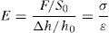
 under compression loading of regular type 3D sample in the sintered state. Apparent elastic modulus was estimated as the slope of the continuous red line. Slopes of the saw-toothed segments are similar (dotted red lines).")
The elastic moduli obtained were corrected for the machine compliance, using a sample of known elastic modulus with similar outer dimension to the present SiC samples, same range of E values and similar testing conditions. For the compression test on the bulk printed specimens, the correction for E incremented the value in 3.5%. However, for the porous structures as they are more compliant the correction meant just a 0.5% increment, accordingly the apparent modulus was not modified as changes were within the dispersion of data.
Strength of massive prismatic specimens were also determined by flexural tests (EM1/50; Microtest, Spain), with a 3-point bending fixture and 15mm of span. The tensile surface of each bar was previously polished and its lateral edges bevelled to diminish the effect of surface flaws. Bend strength was determined as:
where F is the maximum load achieved, L the testing span, and d and b the thickness and depth of the bulk bar, respectively.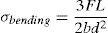
With the aim of eluding the density dependency, all patterns were designed to maintain the same ρ in the 3D structures. Size and weight of the samples were measured in as-printed state and after each thermal treatment in order to estimate the real bulk density.
Fracture surface microstructure of samples was observed with a field emission scanning electron microscope (FESEM, S-4700; Hitachi, Japan).
Results and discussionIn Fig. 4 the bulk density of the specimens is represented as a function of the relative rotation angle between consecutive layers for the successive treatments, evidencing, after each treatment, the uniformity in density values for the different rod orientation designs. It should be noticed that a reduction of density is observed in all the structures after the calcining treatment because of the loss of adsorbed water and the burnt out of organics with an insignificant lineal shrinkage (≈1% from the green state). In the same way, the specimens treated at 1500°C show an average density of 0.53gcm−3 similar for all the design (equivalent to 80–85% of porosity). The modest density decrease with respect to the calcined materials is due to the occurrence of certain mass loss and small shrinkage (≈2%), which both are perfectly normal considering the absence of liquid sintering aids and pressure-assisted sintering methods [18].
 at different states.")
The pioneering work by Ashby et al. [23] evidenced that properties of cellular materials are reasonably explained according to some macroscopic characteristics, namely, solid fraction or geometrical density, and lattice parameters, like the nodal connectivity [23]. As a result, strength, σ, and elastic modulus, E, of porous materials vary with the geometrical density, ρ, according to the following model equations:


where b and c represent materials dependent parameters approaching 1 for stretching-dominated systems and becoming>1 for bending dominated structures. In this context, 3D printed structures can be macroscopically treated as cellular materials.
In terms of design, according to Ashby et al. model [23,24], all above described patterns have no differences among them that could justify mechanical differences. They also show the same nodal connectivity of 4, defined as the number of struts that meet at each node [23]. A bending-dominated failure behaviour should be expected for the designs of these patterned architectures [23,24]. It would also agree with previous results by same authors for similar structures with the regular design, which demonstrated a density dependence of elastic modulus and strength according to fitting models, with b=2 and c=1.5 (in Eqs. (4) and (5), respectively) [18].
Representative stress-strain curves of the diverse structures are compared in Fig. 5 for the different stages, as-printed, calcined and sintered. The smooth loading curve usual of the as-printed samples indicates a viscoelastic behaviour attributable to the remaining polymeric additives from the ink. After the 600°C treatment, the 3D structures become stiffer and abrupt load drops are observed in the stress/strain plots (Fig. 5b) due to non-catastrophic failure associated to fracture of single rods as the structure allows further loading. The removal of the polymeric additives reduces the particle cohesion and accordingly the load bearing capability. Conversely, a strength enhancement is observed for the sintered specimens compared to the calcined sample owing to some particle bonding. At this point, the steep raise in the loading curves (Fig. 5c) also signals an increase of the elastic modulus of the structures. In terms of structure design, the 75° samples demonstrate superior performance at every step.
, calcined (b), and sintered (c) samples.")
Data for E reveal a stiffness increment in patterned structures with the θ angle from 45° to 75° until a maximum value of 300MPa for the sintered 75deg structure, and the same behaviour is observed for σ results (Fig. 6a and b) with values up to 1.4MPa, which represent improvements in the order of 16–55% (σ) and 11–57% (E) between maximal and minimal values for each sample series (as-printed, calcined and sintered). Hence, the structure with filaments at 75° from the horizontal axis is the design with the highest σ and E values at all stages. These improvements are consistent as standard deviations are below 25% (\sigma) and 17% (E).
 and elastic modulus (a) and compression strength data (b) for the structures at the different stages. Connecting lines in plots are just an eye guide.")
Intuitively, the most favourable orientation under compression should correspond to the design with rods oriented parallel to the compression axis, i.e. for the regular design. However, a larger number (≈30%) of rods connecting top and base surfaces occurs in the 75° design compared to the regular design, which would explain its superior mechanical performance. Therefore, despite the robocasting method has the constraint of in-plane filament deposition, it certainly allows optimizing orientation regarding load distribution in the structure by tilting printing direction.
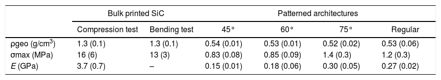
Comparing the mechanical properties of the patterned architectures and bulk printed material is also rather interesting. In Table 2, the strength data, bending and compression tests, of the bulk specimens are summarized, which are surprisingly similar, and data for E and density are also included. The designed macro-porosity of the SiC scaffold produces a reduction in one-order of magnitude of the density respect to the massive structure, inducing an equal decreasing of the strength and elastic modulus. Besides, the 75°-patterned scaffold achieves higher values of σ (1.4MPa) and E (0.3GPa) without significant density differences (∼ 2%) with respect to the scaffold with a regular rods pattern (1.2MPa and 0.27GPa respectively, Table 2).
Geometrical density, strength and elastic modulus for the bulk and porous printed architectures (45°, 60°, 75° and regular rod orientation). In parenthesis are the corresponding standard deviations.
| Bulk printed SiC | Patterned architectures | |||||
|---|---|---|---|---|---|---|
| Compression test | Bending test | 45° | 60° | 75° | Regular | |
| ρgeo (g/cm3) | 1.3 (0.1) | 1.3 (0.1) | 0.54 (0.01) | 0.53 (0.01) | 0.52 (0.02) | 0.53 (0.06) |
| σmax (MPa) | 16 (6) | 13 (3) | 0.83 (0.08) | 0.85 (0.09) | 1.4 (0.3) | 1.2 (0.3) |
| E (GPa) | 3.7 (0.7) | – | 0.15 (0.01) | 0.18 (0.06) | 0.30 (0.05) | 0.27 (0.02) |
In addition, strength and elastic modulus are also compared with published data for different cellular SiC ceramics [12–14,18,19,22,25–32] in Fig. 7. Strength values are fitted using Eq. (5) of Ashby model for a wide porosity range, attaining the best fitting for a coefficient c of 2.5 (Fig. 7a), which is in the range of bending dominated materials [18,24]. The strength data of present materials perfectly meet the dispersion cloud of values at the low end, which is explainable because the used test configuration with Y-axis as loading direction which favours buckling phenomena. Present strength values are lower than previously reported data for similar SiC architected specimens (regular design only) [18], also evidencing the reinforcing effect of the lateral frame walls in those specimens. As for the massive printed material, strengths are similar to those reported for cellular materials of alike density [26,29,30]. Values for fully dense materials are also included in the plot corresponding to the upper right corner to get a complete picture of SiC ceramics [19,25].
![Strength (a) and elastic modulus (b) against density of different cellular SiC ceramics. Diamonds represent data of literature [12–14,18,19,22,25–32] while circles are the data of the present work included in Table 2. Upper guide lines correspond to Ashby et al. models, Eqs. (4) and (5) for different exponents (b=3, 3.5, 4 and c=2, 2.5, 3).](https://static.elsevier.es/multimedia/03663175/0000006000000002/v1_202104020823/S0366317520300212/v1_202104020823/en/main.assets/gr7.jpeg?xkr=ue/ImdikoIMrsJoerZ+w997EogCnBdOOD93cPFbanNd3TCEZuNxhudow/+3Hrh9WJc+mtnYSSPL9K6mfMWVj1qLx4L8NX2lURm/3OFg3Pvwr8OP2GBvTUu+qY5mOUnLfp371WHT6HxV18WTAMLnGzLJaMzPbfsm6XVqjvKa0Q9n0WcuyYEHNspxwS91zPBIh+LukIQiPCPWe6M8e4mx4fdKI7ZsGMtq+tGbYGTdX0ANMyCd8wge78I8LE8auYspgDrYsCqXPWTGzvKqSRLYd5jpnOPavuefmaqshdyxrp4iBEkW2/L1+iM6vDnr4KRAq "Strength (a) and elastic modulus (b) against density of different cellular SiC ceramics. Diamonds represent data of literature [12–14,18,19,22,25–32] while circles are the data of the present work included in Table 2. Upper guide lines correspond to Ashby et al. models, Eqs. (4) and (5) for different exponents (b=3, 3.5, 4 and c=2, 2.5, 3).")
Strength (a) and elastic modulus (b) against density of different cellular SiC ceramics. Diamonds represent data of literature [12–14,18,19,22,25–32] while circles are the data of the present work included in Table 2. Upper guide lines correspond to Ashby et al. models, Eqs. (4) and (5) for different exponents (b=3, 3.5, 4 and c=2, 2.5, 3).
Elastic modulus of present materials is represented in Fig. 7b where the higher E is observed for the 75° material, as occurred for the strength results. This figure includes data for some other SiC materials (cellular [32], architected [18] and partially sintered [26]) merely by way of illustration since diverse test methods were used for calculating E. If we compared E data of alike 3D SiC materials but tested perpendicularly to the printing plane and having a frame [18], no significant differences are observed when selecting structures of similar pattern, i.e. regular scaffold of same density. According to equation [4] for porous cellular materials, a value of b=3.0 can be estimated for cellular SiC ceramics. Nonetheless, a more rigorous fitting would require a wider data pool of E values for this material.
The microstructure of the porous printed bulk SiC is shown Fig. 8, where fracture surfaces (compression and bending designs) are examined by SEM. Fig. 8a describes the orientation of the fracture surfaces in Fig. 8b and c on the CAD model.
, SEM micrograph of fracture surface after bending test (b), fracture surface after compression testing at different magnifications (c, d and e). Dotted black circles show the rod sections whereas yellow lines signal the preferential horizontal orientation of porosity in the Y–Z plane outlining piled rods (b) and the corresponding lines of pores in the X–Y plane separating rods (c). Higher magnification views present the microstructure in a flat area (d) and on a pore surface (e).")
Illustration of the observed sections of bulk specimens (a), SEM micrograph of fracture surface after bending test (b), fracture surface after compression testing at different magnifications (c, d and e). Dotted black circles show the rod sections whereas yellow lines signal the preferential horizontal orientation of porosity in the Y–Z plane outlining piled rods (b) and the corresponding lines of pores in the X–Y plane separating rods (c). Higher magnification views present the microstructure in a flat area (d) and on a pore surface (e).
An obvious hierarchy in the pore distribution of these bulk printed SiC ceramics is observed. Spherical macro-pores (≈100μm diameter) are aligned between layers mostly outlining the printed filaments as the sketched circles indicate (Fig. 8), which are observed from the as-printed to the sintered state. In the horizontal plane (marked as c in Fig. 8a), a similar pore alignment between rods is also seen (Fig. 8c). Furthermore, higher magnification images reveal the presence of submicronic porosity (Fig. 8d and e), owing to the partial sintering [18]. The microstructural features of this printed bulk SiC resemble attributes of closed-pore SiC foams, and accordingly would be an alternative route to make ceramic foams and light SiC components while maintaining good structural resistance. Moreover, the aligned macro-pores between rods allow added control of porosity by variating rod diameter, inter-rod distance, or even the fully pattern, which would affect pore diameter and distribution as well as number of pores per a unit volume, of paramount interest for certain applications.
The analysis of fracture surfaces also reveals an intergranular fracture caused by the weak ceramic bonding and the small grain size of the material. In case of compressive test (Y-axis setting) of the bulk material, the fracture surface also reveals the pore arrangement, thus explaining similar strength data under compression and bending for the bulk materials as porous planes probably act as weakest zones for preferably crack propagation.
SummaryThe present work shows the possibility of optimizing mechanical properties of 3D ceramic architectures by simple modifications of the pattern design; in particular, by changing the rod orientation in woodpile structures. The mechanical results of the patterned structures with different rod orientation reveal a dependency on lattice geometry, as the density and nodal connectivity are constant for all patterns. In particular, both strength and stiffness show a systematic increase for the θ rod orientation of 75° because of its larger number of rods connecting top and bottom surfaces. On the other hand, printed SiC bulk materials develop perfectly oriented macro-pores (≈100μm) reflecting a closed foam appearance and hierarchical porosity. Improving the mechanical properties of cellular structures would also permit optimizing other characteristics such as specific mass reduction or porosity size adjustments, both of paramount interest for certain applications. Therefore, filament printing is a versatile method to produce a wide range of cellular ceramics.
This work was supported by projects MAT2015-67437-R and RTI2018-095052-B-I00 financed by the Ministerio de Ciencia, Innovación y Universidades MCIU (previously MINECO), Spain/FEDER (UE). J.J. Moyano acknowledges the financial support of MCIU/FEDER through the FPI contract ref: BES-2016-077759.
The following are the supplementary data to this article:

