


In this paper, aluminium foil with a tunnel structure was used as a cathode to prepare a lithium iron phosphate composite by electrochemical deposition using propylene carbonate as the electrolyte solvent, and lithium nitrate, ferric nitrate and phosphoric acid as raw materials. The results show that the positive electrode composite is composed of a mixture of an olivine structured LiFePO4 and polyanion Li9Al3P8O29. The chemical composition of the mixture is related to the voltage of the electrochemical deposition and the acidity of the electrolyte solution. For a voltage of 1.8V and pH of 1.0, the composite material deposited in the tunnel of the aluminium foil takes the form of a one-dimensional nanotube, with a particle size ranging from 80nm to100nm. The composite material is closely combined with the aluminium foil. The aluminium foil can be directly used as a positive current collector, with a lithium sheet as the negative electrode. After mounting into a battery, an electrochemical performance test is performed. The battery test results show an initial discharge capacity of 95mAh/g, 79mAh/g and 59mAh/g at 0.1C, 0.2C and 0.5C, respectively. After the material is doped with magnesium and cobalt, the initial discharge capacity of the battery is 100mAh/g and 130mAh/g, respectively, at a rate of 0.1C. The cyclic voltammetry analysis of the battery show that after electrochemical deposition of the element, the symmetry between the oxidation and reduction peaks is increased, and the difference between the oxidation and reduction peak potentials is reduced. Element doping improves battery cycle performance. The AC impedance analysis show that the embedding impedance for lithium ions at the SEI interface is reduced from 300Ω to 250Ω, 100Ω after doping with magnesium, and cobalt. And the reaction mechanism of electrochemical deposition is discussed.
En este trabajo se usó papel de aluminio con una estructura de poro túnel como cátodo para preparar un compuesto de matriz de aluminio de fosfato de hierro y litio por deposición electroquímica usando carbonato de propileno como disolvente electrolítico, y nitrato de litio, nitrato férrico y ácido fosfórico como materias primas. Los resultados muestran que el compuesto de electrodo positivo está compuesto por una mezcla de LiFePO4 estructurado de olivino y polianión Li9Al3P8O29. La composición química de la mezcla está relacionada con el voltaje de la deposición electroquímica y la acidez de la solución electrolítica. Para un voltaje de 1,8V y un pH de 1,0, el material compuesto depositado en el agujero del túnel del papel de aluminio toma la forma de un nanotubo unidimensional, con un tamaño de partícula que varía de 80-100nm. El material compuesto se combina estrechamente con el papel de aluminio. El papel de aluminio se puede usar directamente como un colector de corriente positiva, con una lámina de litio como electrodo negativo. Después de montar en una batería, se realizó una prueba de rendimiento electroquímico. Los resultados de la prueba de batería muestran una capacidad de descarga inicial de 95, 79 y 59mAh/g en condiciones de 0,1, 0,2 y 0,5°C, respectivamente. Después de dopar el material con magnesio y cobalto, la capacidad de descarga inicial de la batería fue de 100 y 130mAh/g, respectivamente, a una velocidad de 0,1°C. Los resultados del análisis de voltamperometría cíclica de la batería muestran que después de la electroquímica Deposición del elemento, se aumenta la simetría entre los picos de oxidación y reducción, y se reduce la diferencia entre los potenciales de pico de oxidación y reducción. El dopaje de elementos mejora el rendimiento del ciclo de la batería. Los resultados del análisis de impedancia de CA muestran que la impedancia de incrustación para iones de litio en la interfaz SEI se reduce de 300 a 250 y 100Ω después de dopaje con magnesio y cobalto. Este artículo analiza y discute el mecanismo de reacción para los compuestos de deposición electroquímica.
The lithium-ion battery cathode material LiFePO4[1,2] has a low preparation cost, good cycle performance, high safety and stability, and offers environmental protection and nontoxicity, with a theoretical capacity of 170mAh/g. As a widely used clean energy carrier, the most commonly used preparation methods are the solid phase method [3,4], hydrothermal method [5,6], microwave method [7,8], etc. To improve the performance of LiFePO4 materials, various modification methods such as doping, nanocrystallization and carbon coating are commonly used. The electrochemical properties of the material can also be improved by controlling the topography of the material. Zhou Y et al. developed a hollow spherical lithium iron phosphate [9–11], which shortened the lithium-ion migration path, reduced the resistance to lithium-ion migration, and improved the material properties. Electrochemical deposition methods have been studied in the preparation of transition metal oxides (LTMOs) for lithium-ion battery materials [12–14]. Zhen Quan [15] et al. electrodeposited a manganese oxide precursor onto an anode gold foil by electrochemical deposition. Then, the surface of the precursor film was immersed into a 0.03mol/L LiOH solution and sintered at a high temperature to obtain a nanocrystalline LiMn2O4 film material. The material showed good cycle performance and stability. Huigang Zhang [16] et al. proposed the preparation of LiCoO2 and LiMn2O4 cathode materials for lithium-ion batteries by direct electrodeposition under high temperature using a molten salt as electrolyte under argon-protected sealed conditions. A mesoporous foamed carbon was used as a deposit carrier working electrode during the electrodeposition process, and a pulse voltage was applied. The prepared material was superimposed into a one-dimensional nanowire structure in a sheet form. The results show that the prepared samples have good performance in terms of crystallinity and electrochemical capacity performance. In summary, during the electrochemical deposition process, the structure of the working electrode plays a role in the template preparation process. Electrodeposition improves the morphology and electrochemical performance of the material.
However, the electrodeposition preparation method has not been reported in the preparation of lithium iron phosphate materials. In this paper, we used an organic solvent as the electrolyte and a high-purity aluminium foil [17] with a tunnel structure as the negative electrode material. At room temperature, a lithium iron phosphate material having nano size holes in the tunnel structure was prepared by way of electrodeposition. We studied the reaction mechanism in the electrodeposition process and tested the electrochemical properties of the composite materials. At the same time, the characteristics of lithium-ion battery current collectors for aluminium foil with a tunnel structure are studied. This study presents a useful exploration for reducing the interface resistance between the current collector and the electrode material.
ExperimentalPreparation of materialsThe electrolyte used in the electrodeposition process was organic propylene carbonate as a solvent. Ferric nitrate, lithium nitrate, and phosphoric acid were added while maintaining a phosphorus:iron:lithium molar ratio of 1:0.3:1. After thoroughly stirring and dissolving, 0.03mol/L of glucose and 0.005mol/L of cationic surfactant cetyltrimethylammonium bromide were added. At 25°C, aluminium foil with a thickness of 110μm was used as the cathode. The surface of the aluminium foil contained a large number of square tunnel pore structures with an inner diameter of approximately 1μm. An equal-area graphite plate is used as the anode, and the distance between the two plates is maintained at 0.4–1.0cm. The graphite plate was used as an anode and electrochemically deposited onto the surface of the cathode aluminium foil under a constant voltage of 1.8V DC. A lithium iron phosphate precursor was prepared. The precursor material was vacuum dried at 90–120°C for 3–6h and then calcined at 550–650°C for 5–8h under nitrogen protection. An aluminium-based positive electrode composite material having a surface-containing lithium iron phosphate conductive active material was obtained. Different transition metal salts such as magnesium nitrate and cobalt nitrate were added to the organic electrolyte to perform metal-ion doping modification. Fig. 1 shows a schematic view of the process preparing a lithium iron phosphate composite by electrochemical deposition.
Characterization of materials
The crystal structure of the composite was characterized by an X’PERT PRO X-ray diffractometer (XDR) produced by PANalytical B. V., the Netherlands. A ∑ IGMA type field-emission scanning electron microscope (SEM) was used to characterize the morphology of the composite material. The composite material was subjected to XPS (American Thermo Fisher) characterization and the elemental valence state was studied. Thermogravimetric analysis of the composite precursor was carried out using a model STA 2500 thermogravimetric analyzer manufactured by Netzsch, Germany.
Characterization of electrochemical performanceWith lithium as the negative electrode, Celgard 2400 as the diaphragm, and 1mol/L Li PF6/EC+DEC (volume ratio of 1:1) as the electrolyte, a CR2032 button battery was assembled in a vacuum glove box filled with argon. A LAND battery test system from the Wuhan Blue Electric Electronics Co., LTD. was used for battery charge and discharge testing. AC impedance test and cyclic voltammetry tests were carried out using an electrochemical workstation manufactured by Shanghai Chenhua Instrument Co., Ltd.
Results and discussionPhase analysis and characterizationFig. 2 shows the diffraction pattern of an electrochemical deposited composite material. The XRD pattern of the prepared sample was compared with the standard cards for olivine-type lithium iron phosphate (JCPDScard No. 40-1499) and the polyanion positive electrode material Li9Al3P8O29 (JCPDScard No. 52-1463). The results show that the composite cathode material mainly contains an olivine structured lithium iron phosphate and polyanion cathode material Li9Al3P8O29. As shown in Fig. 1, lithium iron phosphate is mainly produced by an electrochemical reaction process. However, the polyanionic anode material Li9Al3P8O29 is produced by corrosion and dissolution of aluminium foil in the cathodic reaction process, which is obtained in the subsequent high-temperature heating process.

In the electrochemical synthesis reaction process shown in Fig. 1, the pH value for the acid electrolyte ranges from 1.0 to 1.2. The aluminium foil is used as a cathode, and the Li+, Fe3+, and H+ cations in the electrolyte migrate to the cathode aluminium foil under the action of the cathode potential. At the same time, a corresponding reduction reaction (1) and (2) occurs on the aluminium foil. In this way, the electromigrated Li+ to the cathode and the reduced Fe2+ formed the essential components of the lithium iron phosphate. Meanwhile, in the initial stage of strong acidity, the dissolution reaction of the aluminium oxide film (3) occurs first on the surface of the aluminium foil (an approximately 50nm thick alumina film will be formed on the surface of the aluminium foil in the natural state). After the removal of the oxide film, the corrosion reaction of aluminium metal occurs under acidic conditions (4). As a competitive reaction within the whole cathodic electrochemical process, the obtained Al3+ enters the precursor and is converted into the polyanionic cathode material Li9Al3P8O29 during subsequent heating reaction.
The reactions of the cathode are as follows:
The reduction reaction (5) and (6) of NO3− containing an oxygen radical near the cathode results in the formation of an alkaline gradient around the cathode, thus resulting in deprotonation and dehydrogenation of propylene carbonate (PC) (7). Lithium ions in solution combine with PC− to produce organic lithium salts on the surface of the aluminium foil cathode (8). The metal cations obtained by reaction (1) and (3) and (4) react with PO43− to form the corresponding phosphates, respectively. The precursors for the preparation of the composite materials were composed of the products obtained by reaction (8)–(10) and the mixture of organic propylene carbonate.
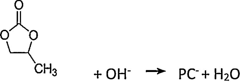
Fig. 3 shows a scanning electron microscopic view of the composite material. Fig. 3A shows the surface morphology of the composites. The results show that the surface composites are spherical particles with sizes in the range of 100–200nm and that the particles are interconnected by a network of carbon. Fig. 3B shows the morphology and structure of the composite material in the tunnel holes of the aluminium foil. The results show that the composite material is deposited in the tunnel walls of the aluminium foil. Fig. 3C and D shows enlarged diagrams for the tunnel structure. The results show that the particle size of composite material in the tunnel is about 80–100nm. The composite material grows along the inner wall of the tunnel with a hollow structure. The tube wall is a one-dimensional nanotube with a thickness of approximately 100nm. The composite material is closely combined with the wall of the tunnel hole. This embedded structure enlarges the connection between the battery active material and collector fluid. The contact area is conducive to reducing the interface resistance, which increases the electronic conductivity.
 surface composite materials in the aluminium foil (b) composite materials (c, d) tunnel structure enlargement in the tunnel of the aluminium foil section.")
XPS elemental analysis for the composites is shown in Fig. 4. Fig. 4A shows the XPS carbon element analysis. The C1 binding energy is 284.8eV, corresponding to the carbon element; C2 is the calibration peak,is the adventitious carbon; C3 has a binding energy of 288eV, corresponding to the CO bond. This shows that in lithium iron phosphate, some carbon exists in the form of carbonaceous compounds. The results show that the carbon element in composites mainly encapsulates electrically active materials in the form of an elementary substance, which plays an important role in the conductivity of the materials. However, some of the carbon still exists in the form of compounds, which affects the electrochemical properties of the materials. How to control the carbon content in the carbon coating needs to be further explored. Fig. 4B shows the analysis of the Fe element in composite samples. The peaks at 711.9eV and 726.58eV correspond to Fe2p3/2 and Fe2p1/2, respectively. The binding energy is close to that of Fe(II). This shows that the iron element in the composite is divalent and that the reaction on the cathode aluminium foil (1) can occur. Compared with the traditional high-temperature solid-state process used for preparing lithium iron phosphate, the electrochemical deposition method directly prepared the trivalent ferrous into a bivalent ferrous, eliminating the process of carbon reduction. Increasing the uniformity of carbon for the in situ coating in electrodeposited composites is beneficial to improving the electrochemical properties of composites. The binding energy of the electron in Fig. 4C is 75.40eV, corresponding to Al2p, which indicates that the Al element in the composites mainly exists in the form of Al3+. Fig. 4D shows the energy spectrum analysis of the composite prepared by adding magnesium nitrate into the electrolyte during electrodeposition. The electron binding energy 1304.5eV corresponds to the orbital binding energy of Mg1S. It shows that magnesium elements are doped into the composite in the form of divalent ions. Fig. 4E shows the energy spectrum analysis of the composite prepared by adding cobalt nitrate into the electrolyte during electrodeposition. The electron binding energies are 791.58eV and 785.03eV. Corresponding to the orbital binding energy of Co 2p 3/2, this shows that cobalt elements are doped into the composites in the form of divalent ions. The results show that metal ions can be effectively doped into composite materials by adding metal ions into the electrolyte during electrodeposition. Lithium iron phosphate is an orthorhombic olivine structure in which tetrahedral PO4 is located between octahedral FeO6 layers, and Li in the intermediate structure is difficult to pass, thereby limiting its diffusion. In addition, FeO6 is connected by a common apex, which has a large bond to the electrons in the outer layer of Fe, resulting in poor electronic conductivity. By adding the metal ions of the same valence state to replace the position of the ferrous ions in the original lattice, the original chemical bond changes, and the crystal structure is destroyed to a certain extent, which facilitates the passage of lithium ions, improves the conductivity, and reduces the impedance. This is beneficial to improve the electrochemical properties of the materials.
 Carbon, (B) Iron, (C) Aluminium, (D) Magnesium, (E) Cobalt.")
Fig. 5 shows a thermal analysis diagram of the composite precursor. Fig. 5 shows that the weight loss of the sample is 10.75% at 120°C, which is mainly due to the content of free water in the precursor of the electrodeposited composites. The weightlessness between 120°C and 260°C is 17.89%, which is mainly caused by the carbonization of the organic matter in the precursor of the composite materials. The weightlessness between 260°C and 440°C is 8.37%, which is mainly caused by the formation of polyanion Li9Al3P8O29. According to the carbon element content in the organic matter, the carbon content in the composites is approximately 7%.
Electrochemical performance analysis
Fig. 6 shows a charge-discharge diagram measured by a battery test system after the composite materials were assembled into button batteries. Fig. 6A shows that the flat charging and discharging voltage platforms for batteries fabricated with the composite cathode occur at approximately 3.5V and 3.4V, respectively. This indicates that the deintercalation process for lithium ions in the lithium iron phosphate and the oxidation and reduction of Fe3+ and Fe2+ is stable. Under the condition of 0.1C, the specific discharge capacity of the prepared sample is 95mAh/g, the discharge capacity is 75mAh/g at 0.2C, and the discharge capacity is 59mAh/g at 0.5C. With an increase in the ratio, the capacity of the battery decreases gradually. Fig. 6B shows the specific capacity of the sample modified by doped metal ions at a 0.1C rate after the first discharge. The specific capacities of the component LFP-Mg doped with magnesium ions and the component LFP-Co doped with cobalt ions are 100mAh/g and 130mAh/g, respectively. Compared with the sample without doping modification, the battery capacity is improved.
.")
Compared with other researchers, the electrochemical properties of lithium iron phosphate prepared by electrochemical deposition still show some gaps. The main reason for the remaining gaps is that the polyanion in the composite materials affects the performance of the battery materials. In addition, the uniformity and content control of the carbon elements in the composite materials need to be further optimized to improve the electrochemical properties of the composite materials.
The cyclic voltammetric test results for composite materials assembled into button batteries are shown in Fig. 7. The graph shows that there are symmetrical redox peaks in the CV curve, which indicates that lithium ions are embedded and removed between the electrodes. The ratio of the redox peak to redox peak is close to 1, which reflects the reversibility of the electrode reaction. The above test results show that the prepared composite material has good stability. However, the results from cyclic voltammetry analysis before and after doping show that the shape of the peak for LFP-Mg is more symmetrical than that for LFP. In addition, the peak current increases and the difference between the oxidation potential and reduction potential decreases. This shows that the modified-doped Mg2+ can improve the reversibility of the battery and the cyclic performance of the battery. Comparing LFP-Co with the LFP-Mg composites, the difference in the redox peak potential was further increased by Co2+ doping, the peak current was further increased, and the symmetry between the redox peaks was further strengthened, which indicated that the polarization degree of the battery was smaller, and the electrical performance of the battery was further improved.

Fig. 8 shows the AC impedance test chart obtained after the composite materials were assembled into batteries. The frequency for the test spectrum ranged from 0.01Hz to 100kHz, and the amplitude was 5mV. The dynamic reaction process for lithium -ion removal and embedding during the charging and discharging of the lithium-ion batteries was studied by electrochemical impedance spectroscopy (EIS) under the equilibrium potential condition. In the discharge state for lithium-ion batteries, the process of Li+ embedment into cathode materials can be divided into four steps: first, Li+ migrate from the electrolyte to the surface of the electrode material, followed by migration into the surface film. Then, charge transfer occurs in the boundary between the surface film and the cathode material. Finally, Li+ diffuses from the surface of the cathode material towards the interior of the material. The charging process for lithium-ion batteries is the reverse of the discharge process. The curve in Fig. 8 is composed of a semicircular arc in the high-frequency region of load-transfer control and a straight line in the low-frequency region of diffusion control. The charge transfer resistance between the electrolyte and the electrode and the diffusion resistance for lithium ions in the charge-discharge process correspond to each other. Thus, they can be represented by equivalent circuit diagrams. In Fig. 8, Rs is the solution resistance, which shows the impedance for Li+ migration in the electrolyte. CPE stands for double-layer capacitor. Rct is a charge transfer impedance, which indicates the charge transfer impedance for Li ions at the interface between the surface film and LiFePO4 material. The impedance for lithium-ion diffusion from the surface to the inside of the lithium iron phosphate material is Zw.
 un-modified. (B) Metal-ion doping modification treatment.")
From the range of the semicircular arc in Fig. 8(A) and (B), it can be seen that the charge transfer resistance of the unmodified LFP and the modified LFP-Co and LFP-Mg in the high-frequency region is 300Ω, 100Ωand 250Ω, respectively. The impedance for the doped cobalt ions in the high-frequency region is smaller than that for the unmodified samples and-doped magnesium ions. LiFePO4 has an orthorhombic olivine structure. The tetrahedral PO4 is located between the FeO6 layers of the octahedron, and Li in the central position finds it difficult to pass through, which limits Li diffusion. In addition, FeO6 is connected by common vertices, which greatly binds the electrons in the outer layer of Fe and makes the electron conductivity worse. Now, by adding metal ions with the same valence state to replace the position of the ferrous ions in the original lattice, the original chemical bonds are changed, and the crystal structure is destroyed to some extent, which is conducive to the passage of lithium ions, an improvement in the conductivity and a reduction of the impedance. The radius of Fe2+ is 0.061nm. The radii of Mg2+ and Co2+ are 0.072nm and 0.065nm. Mg2+ and Co2+ replace the position of ferric ions in the original lattice, which changes the original chemical bond and facilitates the embedding and Embedding of lithium ions, respectively. When the same concentration of nitrate is added to the electrolyte, the lattice defects in lithium iron phosphate caused by cobalt ions enable Li+ to be more easily embedded and desorbed.
ConclusionsIn this paper, nanosized hollow aluminium matrix composites were prepared by electrodeposition using high purity aluminium foil cathode with a tunnel structure, graphite as anode, and a mixture of iron nitrate, lithium nitrate, phosphoric acid, glucose and CTAB as electrolyte in a propylene carbonate organic solvent. The results show that the composite is composed of olivine LiFePO4 and polyanion Li9Al3P8O29. The particle size of the composite material on the surface of the aluminium foil ranges between 100 and 200nm, and the composite material in the tunnel of the aluminium foil takes the form of a one-dimensional nano tube, with a particle size of 100nm. After doping with Co2+, the cell capacity increased from 95mAh/g to 130mAh/g at a rate of 0.1C. The results from cyclic voltammetry and AC impedance analysis show that metal-ion doping improves the cyclic performance of the battery. In this paper, the battery material is prepared on the surface of Aluminium collector, which simplifies the installation process of lithium-ion battery and has good practical effect.

