


Samples of nominal composition Li1.3Fe0.3Ti1.7(PO4)3 with a NASICON-type crystal structure, can be sintered up to 95% of the theoretical density at only 600 °C using spark plasma sintering, SPS. The final pellets however show different colouration in their upper and lower faces, being the upper face white and the lower one pink. The analysis of both surfaces by XPS shows a higher concentration of lithium on the white upper face, as a consequence of the polar diffusion of ions from the positive to the negative rams during SPS. On the other hand the study by XRD and SEM shows the formation of an extra phase in the upper face with nominal composition LiOPO4. A change in the cell parameters of the original NASICON structure is also observed, confirming the diffusion of lithium ions.
Muestras de composición nominal Li1.3Fe0.3Ti1.7(PO4)3 y estructura tipo NASICON se han logrado consolidar mediante SPS (spark plasma sintering) a tan sólo 600 °C y alcanzando una densidad del 95% de la densidad teórica. No obstante, las pastillas obtenidas muestran una diferente coloración en sus caras, siendo la cara superior de colour blanco y la cara inferior de colour rosado. El análisis de ambas superficies mediante XPS evidencia una mayor concentración de litio en la cara superior blanquecina, como resultado de un proceso de difusión polar de iones entre los polos positivo y negativo durante el tratamiento por SPS. Por su parte el estudio mediante DRX y SEM de ambas caras indica la formación de una fase extra en dicha cara superior, con una composición nominal LiOPO4. Además se observa un cambio en los parámetros de red de la estructura NASICON original, confirmando dicha difusión de los iones litio.
LiTi2(PO4)3 and its derivatives have been extensively studied to be used as anodes, cathodes and solid electrolytes in lithium batteries and other electrochemical devices ([1], [2], [3], [4], [5], [6], [7], [8], [9], [10]). Compounds of formula Li1+xMxTi2−x(PO4)3 show values of dc ionic conductivity up to 2 × 10⁻³ S cm−1 ([11]). However, the most important drawback of these compounds to be used is their poor sinterability. Although the packing density of the powders is enhanced with the substitution of titanium by trivalent metals ([12]), it is still not good enough for practical applications. By conventional sintering (CS), i.e. cold pressing plus thermal treatment, we have reported the obtaining of samples with densities as lower as 60% of the theoretical density ([13]). Moreover, this sintering method needs long thermal treatments at high temperature which increases the energetic costs of the product and can lead to loss of lithium during the process.
In order to obtain dense samples in a shorter time and lower temperature, the Spark Plasma Sintering (SPS) can be used. Some articles report the successful application of SPS in LiTi2(PO4)3 and derivatives ([14], [15], [16], [17], [18], [19]). The SPS is a sintering method that uses electrical current to heat the sample at the same time that the pressure is applied, which allows to achieve higher heating rates and shorter sintering times than the conventional sintering treatments. For this reasons, SPS is one of the advance densification techniques that may fulfil the actual requirements on consolidation. In addition to consolidation, SPS is also being applied for the synthesis of different materials ([20], [21], [22], [23], [24]). A SPS unit is schematically shown in Fig. 1. It consists of a uniaxial pressure device, where the water-cooled punches also serve as electrodes, and a pulsed DC generator. A computer-based process controller records the shrinkage, temperature, pressure, average voltage and current during the process. Powders are placed on a die made typically of graphite. Heating is carried out by Joule heating with an electrical current passing through the die and the sample, if it is conducting. The current used in SPS is normally pulsed. The high DC pulse frequency transfers and disperses the local heat throughout the specimen, resulting in a rapid and homogeneous heat distribution ([25]). The effect of pulsed direct current on atomic diffusion kinetics has been investigated experimentally by SPS, in several electrical conductive reaction couples like Mo–Si, B–C and Nb–C ([26], [27]). It has been shown that the presence of an electric current may give rise to changes in phase transformations, temperatures, nucleation and grain growth rates, reactions patterns and deformation behaviours of different materials. The proposed explanations invokes variations of dielectric and magnetic properties of materials, increased diffusion rates, enhanced annihilation of dislocations, and changes in mobility of dislocations and vacancies. Even though it is very difficult to separate the effect of current from that of temperature in SPS, it is quite certain that materials sintered by SPS are exposed to high electric and magnetic fields during sintering, which most probably has an effect on sintering ([25]).
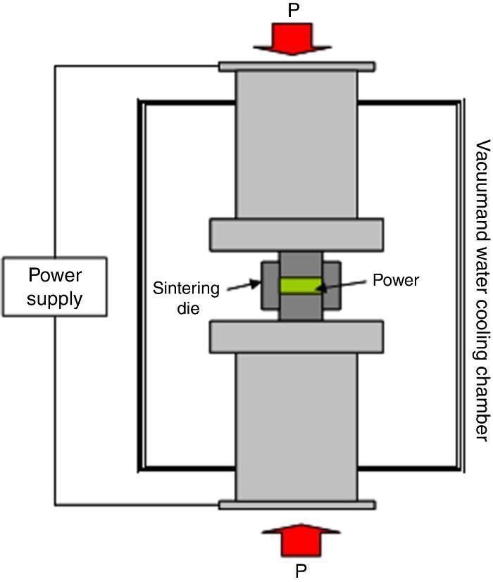
Fig. 1. Scheme of the SPS unit.
The occurrence of redox reactions during the SPS synthesis of Na24Si136 from Na4Si4 and Si together with mass transport has been described ([28]). The oxidation of Si44− takes place at the anode; while Na+ is reduced at the cathode. Since this work, other authors have reported the role of the electrical current during the synthesis of materials and SPS is revealed as a promising novel technique for synthesis and crystal growth in solid state science ([29]).
In this work we report the polar diffusion of lithium ions during SPS in samples of composition Li1.3Fe0.3Ti1.7(PO4)3 as studied by X-ray photoemission spectroscopy (XPS), X-ray diffraction (XRD) and Scanning Electron Microscopy (SEM).
ExperimentalSamples of Li1.3Fe0.3Ti1.7(PO4)3 nominal composition were synthesized by sol–gel chemistry as previously described ([13]). Before sintering, powders were mechanically milled in 2-propanol using ZrO2 balls in a Retsch PM100 Planetary Ball Mill at 100 rpm during 10 minutes. Pellet samples with a diameter of 12 mm and a thickness of 2.5 mm were prepared in vacuum using a uniaxial pressure of 90 MPa. Sintering experiments were carried out in a SPS unit Dr. Sinter 2050 (SPS Syntex Inc., Japan). The samples were loaded in a graphite pressure die and enclosed by graphite papers. The die was heated by allowing a pulsed direct current to pass through. The pulses had a time-duration of 3.3 ms and a pulse sequence consisting of twelve pulses followed by a period of 6.6 ms of no current (12 pulses On:2 pulses Off), with a maximum voltage of 3.5 V and a current of 635 A. The samples were heated up to 600 °C with a heating rate of 100 °C/min and a holding time of 1 min at the final temperature. The temperature was measured with a thermal couple inserted into the graphite die.
For the XRD profile analyses of both faces of the obtained pellets, step-scanned patterns were collected between 2θ (°) 10 and 80 on a Bruker AXS D8 Advance diffractometer in steps of 0.02° and a counting time of 12 s per step. Rietveld refinement was carried out using TOPAS 4.2 software from Bruker AXS ([30]). For microstructural observations, the surfaces of the sintered samples were polished and chemically etched with oxidizing hydrochloric acid, and field emission scanning electron microscopy (FESEM) was carried out using a Cold FESEM Hitachi S-4700 microscope supplied with an energy-dispersed spectroscopy microanalysis probe (EDS). X-ray photoelectron spectroscopy (XPS) was used to characterize the chemical composition of both faces. XPS spectra were acquired in an ultrahigh vacuum (UHV) chamber with a base pressure of 10−9 mbar using a hemispherical electron energy analyser (SPECS Phoibos 150 spectrometer) and a monochromatic AlKα (1486.74 eV) X-ray source. XPS spectra were recorded at normal emission take-off angle, using an energy step of 0.1 eV and a pass-energy of 20 eV which provides an overall instrumental peak broadening of 0.55 eV ([31], [32], [33], [34]). Carbon and hydroxyl (OH) species were detected as contaminants on the surface of the samples, and the signal from adventitious carbon at 284.6 eV was used for energy calibration. The overall surface composition was determined from survey spectra, and regions of interest (Ti2p, Fe2p, O1s, C1s, P2p, Li1s, and Ca2p) ([35]). The samples were exposed to air atmosphere upon preparation. In addition, the sample was cleaned by Ar+ ion bombardment (1 keV, 1.5 μA cm−2, 20 min). This process removes part of the air contamination present on the surface of the sample, which is also very useful to increase the XPS signal and, therefore, to analyze their composition. The integral peak areas after background subtraction and normalization using sensitivity factors provided by electron energy analyser manufacturer were used to calculate the atomic concentration of each element. Data processing was performed using CasaXPS software (Casa Software Ltd., Cheshire, UK).
ResultsThe observed sintering curve is shown in Fig. 2 which represents the linear shrinkage (−ΔL) and the linear shrinkage rate (d(ΔL)/d(t)) versus time. The heating ramp used is also included. The onset temperature, defined as the temperature at which shrinkage starts and generally known as the starting of the intermediate stage of the sintering, is 460 °C. At the final temperature, 600 °C, the linear shrinkage is constant. Once activated, the sintering occurs very fast, within less than two minutes. The final density was calculated by the Archimedes method using water as immersion fluid and was found to be 95% of the theoretical density. The graphite paper was then removed by polishing and the samples were then annealed in air at 700 °C for a few hours to eliminate carbon contamination. After annealing, the pellets showed a different colouration in their upper and bottom faces, the lower face being pink and the upper being white. Fig. 3 shows photos of both faces plus a transversal section evidencing the gradient of colouration between both sides of the pellet. This different colouration in the two sides of the samples led us to conduct a chemical analysis by means of high-resolution XPS measurements. The overall surface composition was determined for each side. Fig. 4 summarizes the results of such analysis. At first glance, the survey spectra showed no big differences between both sides of the pellets, see Fig. 4a (in both cases the presence of calcium signals must be attributed to contamination, probably coming from the polishing step). However, the situation changes when focusing the XPS analyses on selected regions and particularly a notorious difference is observed for the lithium content, as shown in Fig. 4d. This picture becomes clearer when considering not the individual amounts, but the concentration ratios between the different cations of interest: as estimated from the XPS calculations, the Fe/Ti ratio remains unchanged in both sides of the pellet but, systematically, the Li/Ti and the Li/Fe ratios are higher in the white side. Table 1 depicts these calculations from one of the XPS measurements, although it can be taken as representative (raw data from XPS in atoms %). This interpretation of movement of Li+ ions during SPS is supported by the polarity of the dc pulse being positive at the lower ram and negative at the upper one.
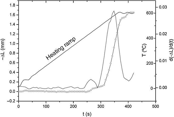
Fig. 2. Linear shrinkage, −ΔL (rounded symbols) and linear shrinkage rate, d(ΔL)/d(t) plotted against time. The applied heating ramp is plotted too.
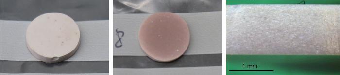
Fig. 3. Photos of the sample showing the different colouration of the upper white face (left picture) and the lower pink-coloured face (central picture). A gradient of colouration is established between both faces which is perceivable in the transversal section of the pellet (picture on the right).
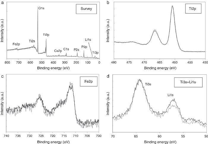
Fig. 4. High-resolution XPS spectra corresponding to: (a) survey, (b) Ti2p core level, (c) Fe2p core level and (d) Ti3s + Li1s regions. Grey lines correspond to the pink lower face of the pellet, black lines to the white upper face.
Table 1. Compositional differences between both sides of the pellets as estimated from XPS measurements. The ratios between the different constituent cations (raw data in atoms %) evidence an incremented content of lithium in the white upper face.
| Ti/Fe | Li/Fe | Li/Ti | |
| Pink lower face | 6.57 | 11.61 | 1.77 |
| White upper face | 6.53 | 15.13 | 2.32 |
Further characterization of the sample was conducted by XRD. Fig. 5 shows the obtained patterns on both sides of the pellets. The main phase in both sides can be ascribed to the Li1.3Fe0.3Ti1.7(PO4)3 nominal phase (there is no diffraction file for this iron containing structure but it perfectly fits the peaks of LiTi2(PO4)3 [ICDD file: 00-035-0754]; a = 8.5129 ¿, c = 20.878 ¿). The biggest difference is due to the formation of LiTiOPO4 [ICDD file: 01-082-1998] in the white upper side, maxima marked with an asterisk in Fig. 5b. The quantitative phase analysis with Rietveld refinement results in a 96.1% of LiTi2(PO4)3 and 3.9% of LiTiOPO4 in that side. Other small peak marked with an arrow in the Figure indicate the presence of a third phase which was difficult to identify, although the best fitting was found for LiFe2(PO4)3 or Li2O. The cell parameters of the main phase (the NASICON-like structure) were determined by Rietveld refinement to be a = 8.5103(6) ¿ and c = 20.967(2) in the pink side and a = 8.5122(6) ¿ and c = 20.956(2) ¿ in the white side. Our results indicate that the pink lower side has higher c and lower a. As it has been reported, the decrease of the c parameter in NASICON-type structures, is related with the liberation of Li+ from the M1 position, which provokes an increase of the repulsion forces between the [Ti/FeO6] octahedra ([36]). In our case we can consider that under the action of the SPS electric field, Li+ ions coming from the M1 position in the pink face of the pellet move to the white face to occupy interstitial M2 positions on the Li1+xFexTi2−x(PO4)3, eventually producing the increase in the a parameter of the NASICON structure as well as the formation of the new phase LiTiOPO4. This result is in close agreement with the previous lithium enrichment of the upper side observed by the XPS measurements.
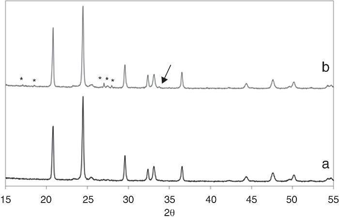
Fig. 5. XRD patterns of the pink lower side (a) and the white upper side of the pellet (b). Asterisks mark the diffraction maxima of the LiTiOPO4 phase while the arrow points to a non-identified secondary phase present in the upper side of the pellet.
Finally, the two sides of the pellets were characterized on the field emission microscope (FESEM). Fig. 6 corresponds to the pink face and, as observed, the chemical etching of the surface reveals a dense single-phase microstructure composed of interconnected submicron-sized grains. Both the high density and the submicronic size of the constituent grains are straight related to the SPS procedure. The etched surface of this pink face was subsequently analyzed by EDS; up to ten measurements in different regions were considered. Unfortunately with this specific spectroscopy it is not possible to detect lithium (too low atomic weight), so any quantification of the EDS results is completely impractical. Even though, we could still use the EDS results to discriminate the presence of different phases; for example, all through the pink face of the pellet the EDS analyses reported a similar spectrum to that depicted in Fig. 6, confirming the single-phase nature of that surface. A different scenario is however observed for the white side of the pellet, where at least two different microstructural features were easily distinguished. On one hand, the same interconnected submicronic grains were detected, their EDS showing a similar spectrum to that of the grains in the pink face (Fig. 7a). But besides, bigger units are now occasionally observed among the submicronic grains, see Fig. 7b. The EDS corresponding to these novel structures indicates a complete absence of Fe in their composition, so it is likely that they can be ascribed to the secondary LiOTiPO4 phase which was observed by the XRD analysis. In addition to the submicron-sized grains already observed in the pink face (Fig. 7a), now bigger grains with an iron-free composition are occasionally observed (Fig. 7b). Therefore, all these results clearly indicate that during the spark plasma sintering processing of the Li1+xFexTi2−x(PO4)3 based material, the applied electrical field promotes a polar diffusion across the samples which causes the migration of lithium ions from the bottom side of the pellet to its upper side. Feasibly, the excess Li+ ions at the upper face would initially locate at interstitial positions and later on, during the annealing conducted to remove the carbon contamination, they produce the crystallization of new Li-rich phases like the one observed by FESEM, XRD and XPS measurements. The whole process eventually produces a colouration gradient in the pellet, from the pink bottom face to the whitish upper face.
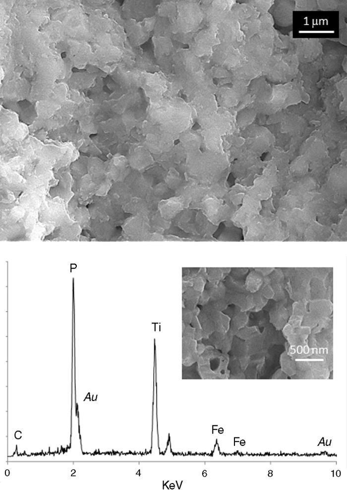
Fig. 6. FESEM micrographs and EDS analysis corresponding to the pink lower face. This same microstructure was observed all along the surface of this side of the pellet.
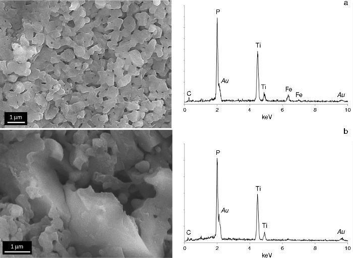
Fig. 7. FESEM micrographs and EDS analyses corresponding to the white upper face.
ConclusionsIn this paper we report the occurrence of polar diffusion of lithium ions during SPS in Li1.3Fe0.3Ti1.7(PO4)3 based materials. Several conclusions can be drawn:
1. SPS permits a rapid densification of Li1.3Fe0.3Ti1.7(PO4)3 at low temperature (600 °C).
2. During the process a gradient of colour is stablished between both sides of the pellets.
3. The study of both faces by XPS shows a higher concentration of lithium in the upper side.
4. XRD measurements show a change in the cell parameters of the NASICON structure which indicates a diffusion of ions from the lower to the upper sides during SPS. Moreover, new phases are formed in the upper side as shown by XRD and FESEM observations.
Acknowledgements
This research has been financed by the Spanish Ministry of Economy and Competitiveness (MINECO) in the frame of projects MAT2010-18432 and MAT2013-40722-R, as well as by the “Fundación Neurociencias y Envejecimiento” (Spain) through grants 4153592 and 4143942. M. Peiteado also acknowledges the Ramon y Cajal Program of MINECO for the financial support.
Received 29 October 2015
Accepted 3 November 2015
Corresponding author. marco.peiteado@upm.es

