


El propósito de este estudio es investigar nuevos activadores alcalinos a través de la reutilización de residuos vítreos en la preparación de materiales activados alcalinamente alternativos al cemento Portland (OPC). Las escorias activadas alcalinamente (AAS) son una alternativa al cemento Portland debido a la alta demanda energética y medioambiental asociada en la producción de este. Además, estos materiales activados alcalinamente ofrecen mejores propiedades que el cemento Portland, como un buen comportamiento mecánico y durable. Sin embargo, el comportamiento reológico de estos materiales ha sido poco investigado.
El presente estudio tiene como objetivo estudiar el efecto del residuo vítreo como activador y como sustitución de la escoria en el comportamiento reológico de las pastas, con una comparación entre los parámetros reológicos y de fluidez de estas pastas frente a los mismos en los cementos normalizados (CEM I and CEM III/B).
Los resultados reológicos de las pastas de escoria activada alcalinamente cuando los activadores fueron una disolución comercial de waterglass y NaOH/Na2CO3 con el residuo vítreo presentaron un comportamiento muy similar, describiendo un modelo Herschel-Bulkley, en donde se confirmó la formación de un gel C-S-H primario en ambos casos. Sin embargo, el comportamiento reológico en los cementos normalizados describe un modelo Bingham. El uso de un residuo vítreo puede ser factible desde un punto de vista reológico en las pastas de escoria activadas alcalinamente.
The purpose of this study is to investigate news activators in the preparation of alkali-activated materials (AAMs) alternative to Portland cements by reusing waste glass. Alkali-activated blast furnace slag (AAS) constitutes an alternative to Portland cement due to high energy and environmental pollution associated with industrial Portland cement. Moreover, alkali activated materials offer a series of higher properties than ordinary Portland cement (OPC), such as better strength and durability behaviour. However, the rheology of these materials has been much less intensely researched.
The present study aimed to study the effect of waste glass as activator and as replacement of blast furnace slag on the rheological behaviour of AAS pastes, with a comparison between the rheological parameters and fluidity of these pastes to the same parameters in standard cements (CEM I and CEM III/B).
The findings show that AAS paste behaviour of rheology when the activator was a commercial waterglass solution or NaOH/Na2CO3 with waste glass was similar, fit the Herschel-Bulkley model. The formation of primary C-S-H gel in both cases were confirmed. However, the rheological behaviour in standard cements fit the Bingham model. The use of the waste glass may be feasible from a rheological point of view in pastes can be used.
Portland cement (OPC) is considered the excellence building material because there is not binder that holds the acceptance that has this material. This is due to its high performance, its good quality/price ratio and because it is possible to find the raw materials to produce it almost anywhere in the world. However, the production of Portland cement is considered a complex and highly intensive process as far as energy is concerned, from the use of raw materials to the production and grinding of clinker.
Additionally, the cement industry is considered one of the industries that emit larger amounts of CO2 into the atmosphere worldwide. In the manufacturing process about 900 kg of CO2 per tonne of cement produced are emitted1, 2, being approximately 5-7% of global emissions caused by humans3. The main CO2 emissions in the cement industry come directly from the combustion of fossil fuels and the calcination of limestone into calcium oxide. An indirect amount of CO2 comes from the consumption of electricity generated by burning fossil fuels and milling processes. Approximately around 33% of CO2 emissions are originated from the fuel and the rest originates from the calcination of limestone (66%)4. The mass balance results in emissions of CO2 and other gases in the production of Portland cement is shown in Fig. 1.5
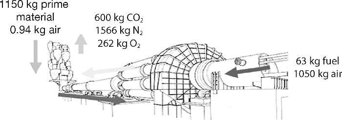
Fig. 1. Mass balance in a typical production process of cement 5 .
At this time reducing CO2 is the most important environmental objective worldwide to reduce the atmospheric concentration of greenhouse gases. Between 2000 and 2006 CO2 emissions increased by 54% worldwide6. Since 2006 and due to population growth and global demand of concrete as the main building material for construction, also cement production expected to increase in each year between 0.8-1.2% to 3.7-4.4 billion tonnes in 2050. As a result of this significant growth in cement production, CO2 emissions will also strongly increase. While global CO2 emissions in a cement plant in 1990 were 576 million tons7, emissions tripled and reached 1.88 billion tons in 2006. If this tendency continues without any measures that might curb the amount of CO2 into the atmosphere due only to cement industry, will become 2.34 billion tons in 20506.
All these possible upcoming events have urged to industry and governments to devote time to study and implement various different promising strategies to reduce the accumulation of emissions of greenhouse gases in the atmosphere. The Kyoto Protocol and the Copenhagen conference were the last overall efforts of the United Framework Convention on climate change. Under these agreements some countries decided to reduce their greenhouse gases8.
Due to some of the environmental problems associated with the production of Portland cement emerge some alternative to try to obtain the sustainable development, for instance, through technological progress in the cement plants; using alternative materials (waste and industrial by-products) as partial or complete replacements for oil, fuel, raw materials or clinker (cement with additions) or across the development of new cementing materials more eco-efficient.
Some of these alternative type cements are those resulting from the chemical interaction between strongly alkaline solutions or amorphous aluminosilicates, which can be natural or industrial wastes such as fly ash or blast furnace slag9, 10, 11, 12. The alkaline solutions used in this process are usually: alkaline metal or alkaline-earth hydroxides (ROH, R(OH)2); weak acid salts (R2CO3, R2S, RF); strong acid salts (Na2SO4, CaSO4·2H2O); and R2O(n)SiO2-type siliceous salts, where R is an alkaline ion such as Na, K or Li. From the standpoint of resistance and durability of the final products formed, the most effective solutions are NaOH, Na2CO3 and hydrated sodium silicates or waterglass solutions13, 14, 15, 16.
The hydrated sodium silicates (waterglass) have provided optimal mechanical resistance in alkali activated materials (AAMs) and good durability. The SiO2 present in the chemical composition of these activators causes the final reaction products to have special characteristics compared to other activators11, 17. These sodium silicates are inorganic chemical compounds produced from combination, in varied proportions, of purity silica salts (SiO2) and sodium carbonate (Na2CO3). The fusion of these materials at temperatures above 1000 °C causes the solid sodium silicate (Na2O×SiO3) as an amorphous glass18, 19 (Fig. 2). This solid silicate is then dissolved in water to obtain the soluble or liquid silicate, which is used in various industrial applications. However, this industrial process is extensively criticized because it is a highly polluting process from an environmental (CO2 emissions) and energy point of view, due to high temperatures used to bring about the fusion18, 19. The estimated results of CO2 emissions in the production of sodium silicates are shown in Table 1, where we can observe that the total emissions estimate is around 1.514 kg of CO2 per kilogram of sodium silicate produced20. However, it is important to note that this study does not include energy expended during the extraction of raw materials so that actual emissions of CO2 are likely that are greater than the estimate provided of 1.514 kg CO2.
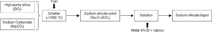
Fig. 2. Commercial manufacturing process of sodium silicate.
Table 1. Estimates of emissions arising due to sodium silicate manufacture 20 .
| Emissions arising from energy expended during manufacturing | ||
| Energy flow (MJ/1000 kg) | Emissions (kg CO2/kg) | |
| Electricity | 3118 | 1.065 |
| Coal | 296 | 0.027 |
| Oil (heavy) | 9 | 0.001 |
| Oil (average/light) | 456 | 0.033 |
| Diesel oil | 144 | 0.010 |
| Gas | 1270 | 0.076 |
| Others | 78 | 0.009 |
| Total | 5371 | 1.222 |
| Emissions caused by transport | ||
| Air emissions (kg/1000 kg) | Emissions (kg CO2/kg) | |
| Carbon dioxide (CO2) | 288.7 | 0.289 |
| Methane (CH4) | 0.128 | 0.003 |
| Total | 0.292 | |
| Grand total (kg CO2/kg) | 1.514 | |
The motivation of this work is to try to get new sodium silicates through the reuse of waste glass. The urban and industrial waste glasses are an amorphous material with a chemical composition consisting essentially of SiO2 (65-75%), CaO (6-12%), Na2O (12-15%), Al2O3 (0.5-5%) y Fe2O3 (0.1-3%), attempting to replace as much as possible the commercial activator (waterglass) employed to the present15.
Glass is an ideal material to be recycled, as once recycled, their use can help save energy in preparing new glasses due to it requiring 26% less energy, needed less expensive and reduces raw materials employed in the preparation of glasses. However, there is a percentage between 10-30% of these waste glasses are not re-allocated to the preparation of new glass containers because they have some kind of impurities either metal or ceramic type. The construction sector plays an important role in the reuse of this percentage of waste glass, using them as pozzolanic additions in the preparation of Portland cement; in the preparation of vitroceramic composites together with other industrial waste or by-products, such as fly ash, slag and ceramic discards; or as a prime material for synthesizing solid sodium silicates or purified silica. In this later application, very recent research by our group14, 15, 21, 22, 23 have shown that sodium silicate-based urban waste glass may serve as an active component in the preparation of alkali-activated slag (AAS) or fly ash (AAFA) cements. The optimal conditions of solubility and concentration of ions, mainly SiO2 and Al2O3, have been established, which allowed us to use these solutions as an alternative activator in the preparation of alkali activated slag or fly ash pastes14, 15, 24.
Alkali activated slag (AAS) or fly ash (AAFA) cements and concretes offer a series of better properties than an ordinary Portland cement (OPC), such as high levels of resistance to short and long times and an excellent durability behaviour in the face of chemical and physical agents, etc. An assessment of recent environmental life cycle25 shows that concretes prepared based on alkali activated slag have a 73% less greenhouses gas emissions, 43% less of energy is required, 25% less water and values about 22-94% less than several parameters related to the toxic environmental impact compared to OPC concrete values.
The rheological behaviour of pastes, mortars and concretes of Portland cement is well known due to the rheology of these systems has been studied thoroughly. However, studies on the rheological behaviour in alkali activated pastes, mortars and concretes are still scarce. Stryczek and Gonet26 conducted a preliminary study of the rheological behaviour of alkali activated slag pastes with sodium carbonates. Subsequently, Palacios et al.27 studied the rheological behaviour in alkali activated slag pastes and mortars with the addition or organic additives. Through this study found that the pastes activated with NaOH fit the model of Bingham; whereas those prepared with the waterglass solution is better positioned to Herschel-Bulkley model28, 29.
Nevertheless, there are still many unknowns to solve regarding the rheological behaviour of alkali activated slag systems. Furthermore, no studies concerning the rheological behaviour of a system of alkali activated slag using solutions from waste glass as replacement of waterglass solution.
With this work we want to show that the use of waste glass as activator in aluminosilicate materials can originate systems with very similar mechanical performance than when a commercial sodium silicate (waterglass) is used and in turn, we want to check what is the rheological behaviour of these alkali activated materials and compared with results obtained with standard Portland cements.
Experimental programCharacterisation of materialsTable 2 gives the chemical composition of the vitreous blast furnace slag (from ENSIDESA factory, Avilés-Spain), the waste glass (from Ajalvir plant, Madrid-Spain) and the standard cements used in this study. The Spanish vitreous blast furnace slag have a vitreous phase accounted for 99% of the slag content and specific surface of this material was 325 m2/kg (EN 196-6). The chemical composition of the waste glass show that the majority oxides present in this type of waste are SiO2, Na2O and CaO. As reference, we used two types of standard cements, CEM I 52.5R and CEM III/B 32.5R (cement with high content of blast furnace slag) where the results obtained by XRF (PHILIPS PW-1004 X-RAY) match which chemical specifications of each of the cements.
Table 2. Chemical composition of slag, waste glass and standard cements (wt.%) determined by XRF.
| wt.% | CaO | SiO2 | Al2O3 | MgO | Fe2O3 | S2– | SO3 | Na2O | K2O | L.O.I* |
| Slag | 41.00 | 35.54 | 13.65 | 4.11 | 0.39 | 1.91 | 0.06 | 0.01 | - | 2.72 |
| Waste glass | 11.75 | 70.71 | 2.05 | 1.17 | 0.52 | - | - | 11.71 | 1.08 | 0.83 |
| CEM I 52.5R | 57.05 | 20.51 | 5.37 | 3.86 | 2.10 | - | 6.37 | 0.64 | 1.44 | 2.35 |
| CEM III/B 32.5R | 49.25 | 29.91 | 7.80 | 6.33 | 0.95 | 1.2 | 1.01 | 0.33 | 0.38 | 2.44 |
* L.O.I = Loss on ignition.
Fig. 3, in turn, shows the particle size distribution of slag, waste glass and the standard cements used in this work (an analyzer Helos 12K of Sympatec mark was used. Samples were analyzed suspended in isopropyl alcohol with an ultrasonic time of 60 s and measurement time of 15 s). According to these results, the particle size distribution of slag and waste glass provided a single mode and they are below 10%, 50% and 90% are shown in Table 3. It is important to note that in this study, a waste glass was used with particle size under 45 microns, as in previous studies (15] it was found as with this particle size the results were better. Rather, standard cements CEM I 52.5R and CEM III/B 32.5R had a size distribution similar in both cases but in this case with the existence of two modes of particle size distribution. Particle sizes under 10%, 50% and 90% are shown in Table 3.
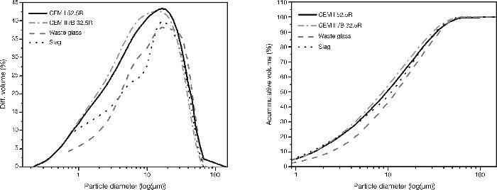
Fig. 3. Standard cements, slag and waste glass particle size distribution.
Table 3. Particle size distribution of all materials used.
| % volume | Particle diameter (μm) | |||
| CEM I 52.5R | CEM III/B 32.5R | Slag | Waste Glass | |
| 10 | 1.76 | 1.88 | 1.41 | 2.34 |
| 50 | 9.49 | 12.61 | 10.89 | 12.20 |
| 90 | 29.34 | 42.03 | 32.67 | 35.78 |
| Specific surface (m2/kg) | 481 | 393 | 325 | - |
The characterization of the starting materials through FTIR and XRD techniques can be seen in Fig. 4 and Fig. 5 respectively. The FTIR spectra were obtained by analysing KBr pellets containing 1.0 mg of sample in 300 mg of KBr on an Nicolet 6700 Thermo FTIR spectrometer. The spectra were recorded after running 64 scans in the 4000-400 cm–1. The XRD patterns for the samples were recorded on a Bruker AXS D8 Advance diffractometer fitted with a Lynxeye super speed RX detector, a 2.2-kW Cu anode no monochromator. The scanning range, from 5 to 60° was covered in a 24-minute period. The instrument was set at 40 kW and 30 mA and the sample was not rotated during scanning.
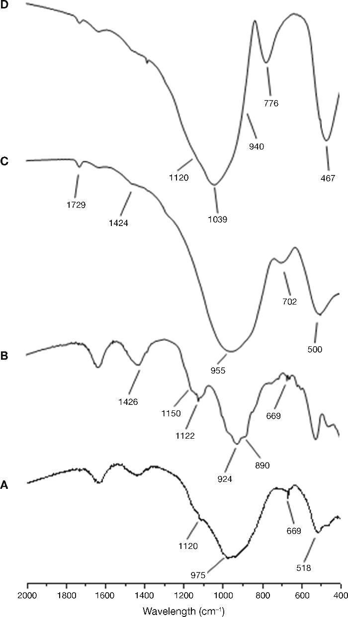
Fig. 4. FTIR spectra for raw material used: A) CEM III/B 32.5R; B) CEM I 52.5R; C) blast furnace slag; D) waste glass.
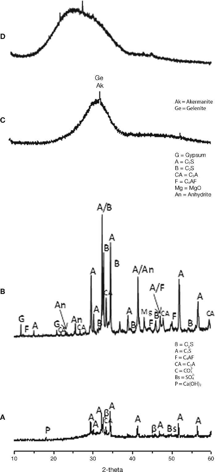
Fig. 5. XRD patterns for raw material used: A) CEM III/B 32.5R; B) CEM I 52.5R; C) blast furnace slag; D) waste glass.
The FTIR spectrum corresponding to the sample CEM I 52.5R (Fig. 4A) shows as majority phase C3S with C2S, C3A and C4AF. The bands are observed at 924 cm–1 and from 874-890 cm–1 correspond to the deformation vibration of silicate tetrahedrons (O-Si-O) of the alite and belite phases. Between 600 and 800 cm–1 were observed several bands corresponding to the vibration of AlO6 distorted octahedral. In the range 1132-1148 cm–1 and 1098-1121 cm–1 two bands associated with asymmetric stretching vibration of the sulfate groups (SO42–), due to the gypsum incorporated into the clinker cement are presented. Finally, the band around 1426 cm–1 corresponds to the asymmetric stretching vibration of carbonates due to the presence of limestone or environmental CO2 carbonation cements (weathering)30, 31. With respect to the spectrum of CEM III/B 32.5R (Fig. 4B) a signal is observed at 975 cm–1 as a wider band due to the presence of blast furnace slag in the cement. Furthermore, the presence of low intensity bands are detected at intervals 1132-1148 cm–1 and 1098-1121 cm–1 associated with the stretching vibration of the sulfate groups ν3 (SO42–).
In the case of the vitreous slag, the FTIR spectrum (Fig. 4C) shows a broad band at 850-1050 cm–1 characteristics of the asymmetric stretching vibration of Si-O in the silicate tetrahedrons. The vibration band appears at 472 cm–1 is assigned to deformation vibrations of silicate tetrahedrons, ν4 (O-Si-O), while between 600-800 cm–1 band is located corresponding to the asymmetric stretching vibration of Al-O bonds of AlO4 slag groups. The bands appear to 1418 cm–1 is assigned to asymmetric stretching vibration ν3 (CO32–) indicating the partial carbonation of the anhydrous slag.
Regarding the FTIR spectrum for waste glass, we can see in Fig. 4D family and characteristics bands with silicates chains found in the central region of the spectrum. The signal appearing at 460-480 cm–1 corresponds to the stretching vibrations of the Si-O-Si and that signal is very sharp. Around 775-800 cm–1 a sharp signal appears corresponding to the symmetric stretching vibrations of the bonds O-Si-O. Acute and wide band appears in the region of 1040 cm–1, which corresponds to the asymmetric stretching vibration and oxygen bridges. Moreover, this signal can be seen two small shoulders, one around 940 cm–1 (corresponding to vibration of the non-bridging oxygen) and a shoulder at around 1120 cm–1 (asymmetrical vibration of Si-O-Si of oxygen bridges). The signal appearing at 1460 cm–1 is due to carbonate groups existing in the glass.
From the XRD results (Figs. 5A and 5B) can be extracted as the majority crystalline phase used in all cements is the C3S or alite. It is important to note that CEM III/B 32.5R cement has a content of amorphous material of 70.27% corresponding to the vitreous blast furnace slag, coinciding with the specifications provided by the supplier of this cement and according to the type of cement to in accordance with UNE EN 197-1:200032.
Slag XRD diffractogram (Fig. 5C) exhibits high amorphous content with a maximum around 2θ=30-32° and only very minor contents of crystalline phases of highest intensity, like gehlenite (2θ=31.42°, 29.13° y 52.09°) and akermanite (2θ=31.14°, 28.87° y 51.78°) appear constituting the slag.
The XRD mineralogical characterisation (Fig. 5D) shows the glass to be an amorphous material, with low range structural order. No peaks attributed to any crystallised compound can be identified except a broad diffraction halo, which is attributed to the glassy phase. The position of the diffraction halo is related to the lime content and sodium content in the glass33, 34, 35, 36.
Pastes preparation and test conductedRheological parameters and fluidity of pastes over time were determined by means of rotational viscosimeter trials and Minislump tests respectively.
The tests were performed for the following cement pastes (see Table 4):
• Commercial standard cements (CEM I 52.5R and CEM III/B 32.5R) used as a reference.
• A vitreous blast furnace slag (BFS) activated with a commercial waterglass solution (Merck, 27% SiO2; 8% Na2O and 65% H2O by weight) with a constant concentration of 5% Na2O by mass of slag (AAS WG).
• A vitreous blast furnace slag activated with 50% wt. NaOH/Na2CO3 solution with the waste glass (25 g per 100 mL of solution) with a constant concentration of 5% Na2O by mass of slag (AAS N/C-waste glass). The process of waste glass treatment for obtaining the alternative activator has been explained in previous studies 14, 15.
• A vitreous blast furnace slag activated with 50% wt. NaOH/Na2CO3 solution (5% Na2O by mass of slag) with waste glass, with a substitution of 10% of the slag by the residual glass waste obtained after solubility process (AAS N/C-glass+10%).
Table 4. Physical and chemical characteristics of the solutions and sample labelling.
| Sample name | Activator type | SiO2/Na2O | L/S |
| AAS WG | Commercial waterglass | 0.86 | 0.55 |
| AAS N/C-glass | NaOH/Na2CO3 + waste glass | 0.86 | 0.55 |
| AAS N/C-glass+10% | NaOH/Na2CO3 + waste glass + 10% residual glass waste | 0.86 | 0.55 |
| CEM I 52.5R | Water | - | 0.45 |
| CEM III/B 32.5R | Water | - | 0.35 |
The liquid/solid ratios used in the rheological testes are shown in Table 4. In all cases the consistencies were similar according to standard UNE 80-116-86.
Variation in shear stress pastes at a constant shear ratePrior to the introduction of pastes in the viscometer, the pastes were prepared by mechanically stirring a mix of 80 g of binder (cement or blast furnace slag) with at a liquid/solid ratio fixed (see Table 4) for 3 min. In the case of the pastes with the replacement of blast furnace slag by the solid residue of the waste glass (10% wt) after attack with NaOH/Na2CO3, the solids were premixed before paste preparation. All pastes were tested for 30 min on a Haake Rheowin Pro RV1 rotational rheometer fitted with a serrated cylindrical rotor and operating at a constant shear rate of 100 s–1.
Determination of rheological parameters: yield stressPaste rheological behaviour was characterised by determining yield stress, using the aforementioned rotational rheometer. The procedure consisted of pre-shearing at 100 s–1 for 2 min, followed by ramping up from 0 to 10 s–1 in 1 min and from 10 to 100 s–1 in 1 min and then ramping down from 100 to 50 s–1 in 1 min and from 50 to 0 s–1 in 1 min. This cycle was repeated six times, with 5-sec pause in between cycles28, 37. The test procedure is depicted in Fig. 6. The yield stress and plastic viscosity values used in the calculations were the means of at least three trials conducted on pastes activated with the same solution.
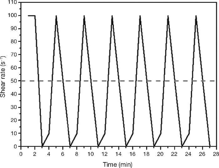
Fig. 6. Dynamic rheological testing with standard Portland cements and AAS pastes.
Paste fluidity (Minislump test)Paste fluidity was determined with the Minislump test38. The pastes were prepared in a mixer (Ibertest Autotest 200/10) first for 1.5 min at low speed (140 rpm) and after a 30-s pause, for 1.5 min at high speed (285 rpm). At the specified times, the pastes were placed in a tr uncated cone measur ing 190×381×572 mm, which was the capsized and emptied. The pastes were dropped 10 times on a flow table and the diameter was measured in three directions: the values used were the arithmetic means of these measurements. The pastes were prepared with 500 g of solid (cements or blast furnace slag or residue solid of waste glass and slag) and the same liquid/solid ratio used for rheological measurements.
Results and discussionVariations in shear stress in AAS pastes at a constant shear rateIn the CEM I 52.5R paste (Fig. 7A), once introduced into the viscometer, the shear stress value initially reaches 300 Pa to experience low steep up stress of 100 Pa to 420 seconds after to start of trial to remain constant. This is because in this cement, hydration effect causes some initial flocs responsible for higher initial values of shear stress, around 300 Pa. As a result of constant rotation, these flocs are broken resulting a fluid paste with the corresponding decrease in shear stress values.
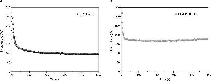
Fig. 7. Shear stress vs time in standard cements: A) CEM I 52.5R and B) CEM III/B 32.5R.
Due to the difference in chemical composition between the CEM I 52.5R and CEM III/B 32.5R, where the latter has a content of amorphous phase of 70% corresponding to the addition of blast furnace slag, is a factor determining to explain the results corresponding to its rheology. In this case it is shown that stress values are very similar to those of CEM I 52.5R pastes (Fig. 7B). However, the shear stress values have a descent more pronounced, reaching the stability in just 90 seconds with a value of about 175 Pa, where these shear stress values are 75% higher than CEM I pastes values.
High stress values are due to the morphology of the slag grains, which have an structure with a greater number of edges, giving to the paste these high shear stress values. Moreover, the rupture of the flocs is faster in this case because the hydration in these pastes is much lower than in Portland cement, resulting fewer hydration products than in CEM I 52.5R pastes. The effect of addition of blast furnace slag percentage in the rheology of the pastes was studied by Palacios et al.39 where it was found that with a higher percentage of addition, the pastes showed higher values of normal shear stress.
When slag pastes are activated with different activators used in this study, the rheological behaviour depends on the type of activator used (Fig. 8A). When the activator was a commercial waterglass solution, the behaviour of this paste was peculiar because there is a case of “false setting”. In this case the initial values of shear stress is lower (78 Pa) than in previous cases. In the early stages of hydration/activation exist a drop in the values of stress to make way then a rapid increase thereof, reaching its maximum value to 420 seconds after starting the test, with a value of 60 Pa. It reaches this maximum; a decrease of 33% in the values of stress exists in this type of pastes to stabilize at 40 Pa to 900 seconds after starting the test. According to the literature40, 41, the slag grains immediately after contact with the solution are surrounded by a thin layer of primary C-S-H gel from interaction between silicate ions from sodium silicate solution with Ca2+ ions from the blast furnace slag. In this situation the slag grains are bonded by Van der Waals force larger flocs. During the early stages of rheological testing these flocs are partially separated but rapid and massive precipitations of C-S-H primary gel continuous and form flocs larger. In the experimental conditions used, the constant stirring of the sample causes the breakage of flocs, which explains the decrease in shear stress causing that the paste flow. According to previous studies28, 39, 41, 42 once exceeded the threshold value, total disruption of the structure of the f locs and the consequent decrease of the shear stress values are detected to keep these constant.
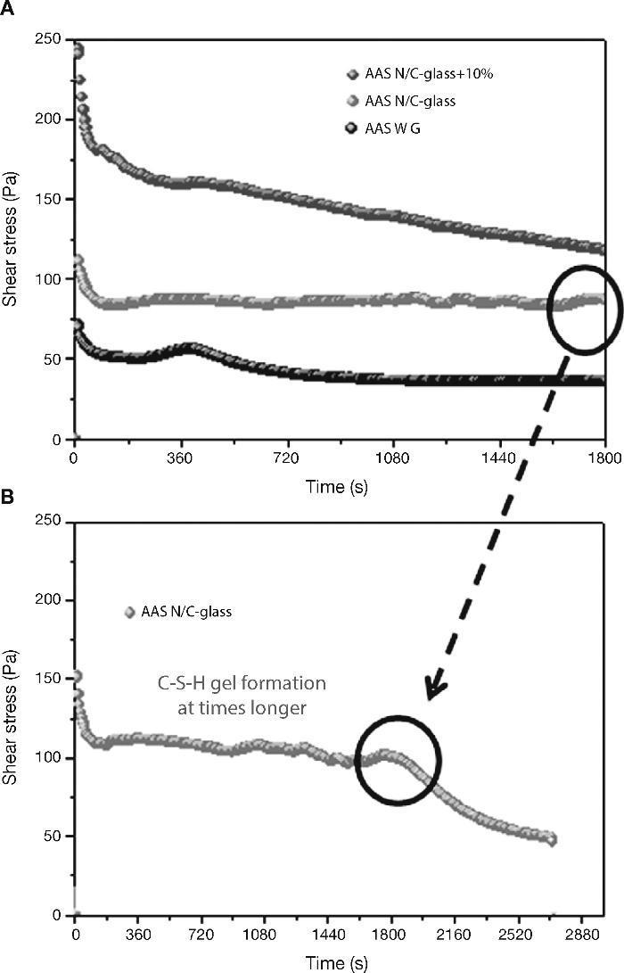
Fig. 8. Shear stress in alkali activated slag with different activators: A) AAS WG, AAS N/C-glass and AAS N/C-glass+10%; B) AAS N/C-glass+10% at times longer.
When the activating solution used was NaOH/Na2CO3 with the waste glass (AAS N/C-glass)14, the values of shear stress obtained at constant shear rate reflected a very different rheological behaviour. The initial shear stress value reaches a value of 112 Pa, down to 70 seconds and from this moment is maintained between 82 and 85 Pa. To explain this behaviour is important to emphasize the different silica source and silicon environment used for this solution respect of commercial waterglass solution. In previous studies Torres-Carrasco et al.15, 24 determined by 29Si NMR that the spectrum for the post treatment liquid, exhibited a single signal at around –71 ppm, associated with the presence of Q0 units, i.e., dissolved Si monomers. This is important because according to the literature43, the effectiveness of Si in waterglass systems rises with declining condensation and polymerization of molecule in the medium. Also the original waste glass have a certain content of impurities that they can react with the basic solution resulting reaction products which can produce changes before reaching a determined value of stress. The initial mechanism of reaction is the same that waterglass solution, producing in this case also the formation of a thin layer of C-S-H gel by the interaction of the silicate ions from solution with Ca2+ ions form blast furnace slag. However, in this case to 30 minutes of test is not observed significant changes in shear stress.
The main reason of this behaviour is the different source of silicon, due to in this case, the silicon is from waste glass44.
In order to check if the primary C-S-H gel is formed in this paste at longer times (Fig. 8B), the test was prolonged for 40 minutes at the same rotational speed of 100 s–1. As occurred in the slag paste activated with waterglass solution, in this case a signal is also observed around 1800-2000 seconds, after which the stirring conditions of the test break the structure of flocs and descending the values of shear stress to these remain constant. It is confirmed that the activating solution from the waste glass generates primary C-S-H gels longer than commercial waterglass activators.
Finally, when the activating solution was NaOH/Na2CO3 after solubility process of waste glass and with 10% substitution of slag by the residual glass waste (solid residue) from solution process (AAS N/C-glass+10%), the rheological performance of this paste is quite different than all other, with a constant decreasing in shear stress values constant during the test. In this case a constant value of the shear stress is not reached. In these trials, although the test was repeated four times, was not achieved in either case homogeneous value, observing heterogeneous stress values between 250-100 Pa. This behaviour is probably due to the replacement of blast furnace slag by residual glass waste (solid residue). This partial replacement appears to inhibit or delay the reaction between the slag and the activator without the apparent formation of primary mentioned C-S-H gel in testing time. In any case, this inhomogeneity shows that these pastes are not viable from a rheological standpoint for their use, at least in pastes.
Determination of rheological parameters: yield stressIn the hysteresis cycles of standard cements (Fig. 9A) follow a straight line with a rise in the early parts of the cycles and a decrease in the final stages of the same after reaching the maximum speed of 100 s–1. It is demonstrated the linear relationship between the rotational speed and the shear stress and thus, the possibility of using the Bingham model (Eq. 1) to characterize these materials.
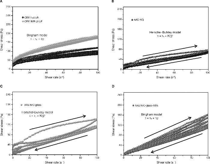
Fig. 9. Pastes hysteresis cycles: A) CEM I 52.5R and CEM III/B 32.5R; B) AAS WG; C) AAS N/C-glass; D) AAS N/C-glass+10%.
On the other hand, emphasizes the great similarity between the hysteresis cycles of the alkali activated slag with waterglass (Fig. 9B) and the alkali activated slag with NaOH/ Na2CO3 and with the waste glass (Fig. 9C). In previous studies28, 39, 41, 42 have been shown that the rheological behaviour of alkali activated pastes with waterglass is adjusted to Herschel-Bulkley model (Eq. 2). In this study it was found that when the activator comes from the solubility process of waste glass, the model that explains the rheology of their pastes is also Herschel-Bulkley.


As to the mixture with partial substitution of slag by attack waste glass (AAS N/C-glass+10%), the hysteresis cycles show a behaviour comparable to standardized cements (Fig. 9D). The most likely cause of this behaviour is the absence of reaction during the process. When the slag is replaced by waste residue, the latter have prevented the activation of the slag was developed, thereby obtaining results similar to those of standard cements hysteresis cycles. Again the results denote heterogeneity. The rheological behaviour ot these pastes fits better to Bingham model.
In Fig. 10 the results of the shear stress values of standardized pastes and alkaline pastes are shown. In the case of CEM I 52.5R the values of shear stress registered remain constant around 50-55 Pa. The defloculation during the test explains that the effort remains constant. These results are consistent with results obtained by other authors29, 30 and with the results of constant shear rate. However, CEM III/B 32.5R pastes present higher values of shear stress due to the morphology of the slag. In this case, the shear stress values are around 75-80 Pa, and again, the deflocculation test explains this behaviour constant of stress values.
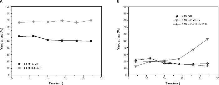
Fig. 10. Yield stress in A) CEM I 52.5R and CEM III/B 32.5R; B) AAS WG, AAS N/C-Glass and AAS N/C-Glass+10%.
Fig. 10B shows the behaviour of the shear stress for alkali activated slag pastes with different activator solutions. When slag is activated with commercial waterglass solution (AAS WG) an increase in the value of stress is produced in the second cycle (25 Pa) and later decrease the values in the third cycle (15 Pa), representing a decrease of 40% and kept constant the rest of the trial. These changes in the values of shear stress are consistent with the behaviour of this paste to constant speed (see Fig. 8). In both studies is observed an increase of stress between 5-10 minutes due to hardening of the paste suffered associated with the formation of a primary C-S-H gel.
The behaviour that the slag paste describes when the activator was NaOH/Na2CO3 with the waste glass (AAS N/C-glass) is different when the activator was a commercial waterglass solution being the chances in the stress shear values more prominent. Importantly, the results obtained in these pastes a clear increase in stress values from the fourth cycle is observed, which suggests that from that moment the paste hardens reaching a value of 52.8 Pa, a very high effort to be an alkali activated slag. It seems clear that the increase in yield stress values in the last cycles correspond to the formation of a primary C-S-H gel, appearing delayed with regard to activated slag paste with waterglass solution and with more intensity, mainly due to the difference source of origin of both activators.
Finally, when the slag is activated with NaOH/Na2CO3 after treatment of waste glass and with 10% of replace of the slag by attack waste glass, again the variability is very high in all tests performed in these pastes. We can say like in the previous case that no reaction between the slag and the alkaline solution due to the partial substitution of the slag by attack waste glass. The lack of reaction of the slag causes a constant decrease in the shear stress without changes observed like in the other two alkaline pastes by the formation of primary C-S-H gel.
Paste fluidity (minislump test)Fig. 11 reflects the behaviour of all cement pastes analyzed, taking four measurements at each measurements times in order to highlight the differences in the behaviour of the same pastes, especially between standard cement pates (CEM I 52.5R and CEM III/B 32.5R) and blast furnace slag pastes activated with different activators.
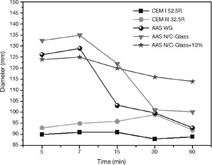
Fig. 11. Minislump values for standard cements and AAS pastes with different activators.
Regarding the results for CEM I 52.5R pastes, it appears that the fluidity of the cement paste is constant over time since the diameter of the mix remains constant throughout the test. This is also consistent with the shear strees values analyzed. The presence of a high percentage of addition of slag in the CEM III/B 32.5R not supposed a excessive change in the fluidity respect to CEM I 52.5R pastes, although this is slightly larger at all times. As in the case of CEM I 52.5R pastes, the fluidity of CEM III/B 32.5R remains constant during the test period.
The behaviour after mixing of the slag with any alkaline activator is very different from the standard cements, especially in the early stages of testing cements. For the testing of 5 to 7 minutes there is an average size difference of mix between the standard pastes and the alkaline systems around 28%.
With the commercial waterglass solution the slag pastes show a complex and changing behaviour in the first moment after mixing. In the early stages of testing, we found a very fluid paste with high values of diameter, reaching 126 cm and 129 cm after the first 5 to 7 minutes of the test. After this first trial, the change in the fluidity of the paste is huge (there is a decrease of 21% of the diameter of the mix), reaching values close to those obtained in standard cement pastes at 15 minutes. Subsequently, the mix diameter continues to decrease but in a way much less sifnificantly. We can say that the behaviour of the paste after 15 minutes remains constant from a viewpoint of fluidity. As in previous trials the formation of primary C-S-H gel produced a change, in this case the change more important occurred between 7 and 15 minutes. In this static test the formation and subsequent break in the primary C-S-H gel is later than in the rheological test at share rate (constant speed). The reason of this delay is the simple fact that in this trial did not submit to the paste to any effort after mixing, do not break the primary gel and therefore the gel causes a hardening of the paste and thus a decrease values in the fluidity.
When the solution was used NaOH/Na2CO3 with the waste glass, the initial behaviour of the activated slag paste was very similar to the activated slag paste with commercial waterglass solution. The main difference observe is that the change in the fluidity of the pastes is in this case later and steeper than in slag activated with waterglass solution (in this case the reduction in the diameter values of the mix was 25% between 7 and 30 minutes). As in the previous case, the behavior remains constant after this change in the fluidity, although in this case the stability is not reached until mix measurement at 30 minutes. This late behaviour respect to the alkali activated slag paste with waterglass solution was reflected in the constant share rate, being the most likely cause the differente nature of the silica may have a less reactive behaviour at early times15, 24.
Finally, the behaviour of slag activated with the solution from the waste glass and 10% replacement the blast furnace slag by residual glass waste changed respect to the previous two, where here the fluidity low gradually causing that if the test will lengthen, testing diameters of the mix be achieved close to those of standard cements. As discussed in the previous sections the main problem of this paste is the lack of homogeneity in the mixture of the blast furnace slag with the atack waste glass from the reaction between the waste glass and NaOH/Na2CO3 solution. This inhomogeneity does not allow that the activation of the slag takes place as in the other two alkaline pastes.
ConclusionsThe key conclusions to be drawn from the present study are listed below:
a) The data presented here will be valuable in the design and development of high-performance, durable pastes based on alkali-activated slag materials with waste glass as activator, and in the selection and application of appropriate testing methodologies for these materials so the use of waste glass is a good alternative to traditional or conventional activators.
b) The rheological differences observed in the different tests between the standard cements and the alkaline cements are due to the formation of the primary C-S-H gel in the latter. It is found that this gel formation is a change in the properties of pastes during the times of measured tests, however, standardized cements show a strong stability in all trials.
c) It is demonstrated the feasibility of the standard cements due to the degree of stability shown by both, essentially through the Minislump test. For alkali activated slag pastes with waterglass solution (AAS WG), it is evident that the fluidity change, with a hardening at 15 minutes which can be a problem for its using in the construction. One solution to this might be to provide a longer mix to break the gel or introduce some substance to delay the formation of primary C-S-H gel. In any case, the values of fluidity are similar to Portland cements, so workability would be acceptable.
d) To analyze the feasibility of pastes which incorporating waste glass to its possible use and application in construction, we must differentiate between the solution from waste glass after the solubility process (AAS N/C-glass) and the systmen which replaced the slag by residual glass waste (AAS N/C-glass+10%), using the same activating solution (NaOH/Na2CO3). As to the first, the variation in shear stress at a constant shear rate and with the determination of rheological parameters (yield stress and plastic viscosity) show stability for at least the first 20 minutes of the test. However, when not subjected to this paste to a continued effort (Minislump test) occurs a major change in their fluency in just 7 minutes test. Despite showing a significant change in the values of fluidity, the final values provide sufficient fluidity for good workability (very similar values to those of standard cements values). Furthermore yield stress obtained and the shear stress at constant speed ensures that the reaction between the blast furnace slag and the alkaline solution have been well developed. As a result of all this, we can conclude that this use of the waste glass may be feasible from a rheological point of view in pastes can be used, therefore, this type of solutions for activation of blast furnace slags are a good alternative to traditional solutions.
e) For the replacement of the slag by attack waste glass (AAS N/C-glass+10%), all tests show a clear inhomogeneity, possibly driven by the difficult mixing between the attack waste glass and the slag. As a result, the slag is not properly activated resulting a paste shows no stability. We can conclude that due to heterogeneity and lack of alkali activation shown in these pastes, this way to use the waste glass is not suitable from a rheological point of view to obtain viable pastes.
Acknowledgments
The present research was funded by the Ministry of Economy and Competitiveness under projects BIA2010-15516 and BIA2013-47876-C2-1-P and under the CSIC project 200460E065. The authors wish to thank P. Rivilla for her assistance with the rheological analyses and A. Gil for his aid with the laboratory trials.
Received 19 January 2015
Accepted 25 February 2015
Corresponding author. mtorres@ietcc.csic.es

