

It has been studied the possibility of using a graphite–cement paste anode for combined treatments of electrochemical chloride extraction plus cathodic protection on reinforced concrete elements. These treatments would be interesting in cases of structures heavily contaminated with chlorides and continuously exposed to a harsh chloride environment. It has been shown that, in the experimental conditions of this work, the anode is not damaged during the electrochemical chloride extraction step. The application of a previous chloride extraction step allows working with a lower current density at the cathodic protection step, which reduces the risk of damages of the anodic system. A chloride barrier effect parameter has been defined, based on the reduction of the chloride uptake by concrete, due to cathodic protection action, referred to the chloride uptake of the reference (not treated) specimens. The values of the chloride barrier effect parameter found in this work are about 20%.
Se ha estudiado la posibilidad de utilizar un ánodo de pasta de grafito-cemento para tratamientos combinados de extracción electroquímica de cloruros y protección catódica de elementos de hormigón armado. Dichos tratamientos serían interesantes en casos de estructuras contaminadas con cloruros y permanentemente expuestas a un ambiente salino agresivo. Se ha demostrado que, en las condiciones de este trabajo, el ánodo no resulta dañado durante la etapa de extracción de cloruros. La aplicación de una etapa previa de extracción de cloruros permite aplicar la protección catódica con una densidad de corriente menor, hecho que reduce el riesgo de daños del sistema anódico. Se ha definido un parámetro de efecto barrera de cloruros, basado en la reducción de la penetración de cloruros, debida a la protección catódica, referida a la penetración de cloruros de referencia (sin protección catódica). Los valores de dicho parámetro encontrados en este trabajo son del 20%, aproximadamente.
Several electrochemical techniques have been successfully used to the protection and remediation of steel corrosion in reinforced concrete structures. All these techniques are based on the lowering of the electric potential of steel [1–7]. This effect can be obtained both by connection to a less noble metal, as in cathodic protection (CP) by sacrificial anodes, or by connection to the negative pole of an electric direct current source, as in CP by impressed current [8–12]. The techniques can also be classified in permanent and temporary techniques. Permanent techniques are CP, whose aim is to stop the steel reinforcement corrosion, and its variant called cathodic prevention (CPre), following Pedeferri et al. [9,11]. The objective of CPre is to prevent the initiation of steel corrosion in new structures. On the other hand, temporary techniques are those intended to change the prevailing corrosion conditions of the structures by lowering its chloride content, such in electrochemical chloride extraction (ECE) [13–18], or by increasing the pH of concrete, such in electrochemical realkalization (ER) [19,20]. In this work we concentrate on applications of the techniques aimed to prevent the onset of corrosion (CPre), improve the prevailing conditions (ECE) or stop the corrosion of steel reinforcement (CP), due to chloride contamination of concrete, excluding sacrificial anode applications.
All the electrochemical techniques have in common the reactions at the surface of steel, the cathode, i.e. oxygen reduction to produce hydroxide ions (the basis of ER), and eventual hydrogen gas evolution if negative enough potentials are reached. Hydrogen production is considered as a potentially harmful process, due to the possibility of hydrogen embrittlement of high strength steels [5,6]. Besides to these reactions the system benefits also from effects due to migration of ions induced by the electric field: hydroxide (OH−) and chloride (Cl−) ions move from cathode to the external anode. This latter effect is the basis of ECE. The permanent techniques, i.e. CPre and CP can be considered as more sophisticated in the sense that they need to guarantee the maintenance (CPre), or the new formation and maintenance (CP), of the passivating layer on steel, by maintaining the potential of steel below the pitting potential imposed by the presence of a certain Cl− concentration in the concrete's inner pore solution [9–12]. These electrochemical conditions induce a reduction of the ratio of the concentrations of chloride and hydroxide ions, [Cl−]/[OH−], near the steel. A non-negligible contribution to the maintenance of the passivating layer comes from the so-called chloride barrier effect acting in CPre and CP applications on steel reinforced structures permanently exposed to an aggressive chloride environment [9,11].
The operation conditions of the abovementioned electrochemical techniques differ in each case. CP and Cpre, applied to reinforced concrete, need using a permanently fixed anode, which is usually an embedded metallic wire mesh, typically a titanium mesh activated with mixed metal oxides, or they use conductive coatings or overlays, such as conductive cementitious overlays [21–24]. CP typically applies current density values between 5 and 20mA/m2, while CPre needs only 1–3mA/m2. Nevertheless, in the case of CP the actual current density needed to effectively protect the steel is higher the higher is the Cl− content of concrete. The success of CP or CPre depends greatly on an optimum design of the anodic system, able to provide an adequate current distribution on the steel reinforcement [9]. ECE, as a temporary technique aimed to reduce the Cl− content of concrete, uses external anodes and electrolytes [25], although it has been demonstrated that a conductive cementitious anodic overlay can also be used as the anode for ECE [26,27,28,29]. The typical current density for ECE applications on reinforced concrete elements is in the range 1–5A/m2, while the total electric charge passed is usually between 1×10⁶ and 5×10⁶C/m2. From an electrochemical point of view the current density should be defined as referred to electrode surface, i.e. the surface of the steel cathode. However, in engineering field applications it is sometimes difficult to know the steel reinforcement area. So, many times the current density is referred to exposed concrete surface, which, in the case of anodic overlay systems is equal to the anode area.
In the case of CP a critical point of concern is the possibility of malfunction of the anodic system, due to the acidity produced by the electrochemical reactions at the anode, which can impair the contact between the embedded conducting material of the anode and the surrounding cement paste. This risk increases when the applied current density is higher than 20mA/m2[21].
The Department of Civil Engineering of the University of Alicante has been conducting research on the use of conductive cement pastes (CCP), based on mixes of cement with different carbonaceous materials, as anodic coatings for applications of electrochemical techniques on reinforced concrete [24,26–31]. One of the most appealing possibilities offered by these permanent anodic overlays is the possibility of combined successive treatments of ECE plus CP, without changing the anode. This combination of treatments may be convenient in the case of structures heavily contaminated with Cl− ions, whose chloride environmental load is expected to be maintained high in the future, for instance the case of reinforced concrete exposed to de-icing chloride salts, or a harsh marine environment. In these cases it may be deemed necessary to first reduce the Cl− content of concrete by applying ECE, and later maintain the steel protected by a permanent CP treatment, without the need to apply a too high CP current density, thus reducing the risk of malfunction of the anode due to the acidity produced at its surface.
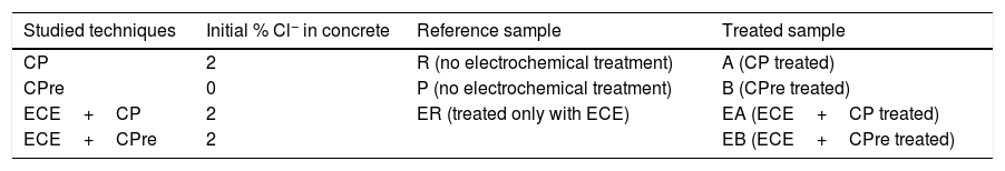
2MethodologyTable 1 indicates the nomenclature of the specimens and the electrochemical treatments applied to each one. The specimens intended for CPre trials (P and B) were prepared with chloride free concrete, since the CPre treatments are designed for being continuously applied to newly constructed structures, starting from the very beginning of the structure's service life [9,11]. On the other hand, the rest of specimens dedicated to testing the CP, ECE+CP or ECE+CPre were prepared with concrete admixed with Cl− ions. The CP treatments are known to allow stopping an ongoing reinforcement corrosion process due to chlorides. Finally, the combined treatments, (ECE+CP and ECE+CPre), are tested here to represent situations in which, the ECE technique is first applied to reduce an initial excessive Cl− content, but afterwards it is deemed convenient or necessary a subsequent application of a continuous protective treatment, (CP or CPre), because the structure will follow being exposed to an aggressive chloride environment. It must be stressed that all specimens included in Table 1, even those that were not given any of the electrochemical treatments (R and P), were subjected to the same salting regime during the 24 weeks period that lasted the CP or CPre treatments: 65ml NaCl 0.5M weekly sprayed onto the concrete or anodic overlay surface, in order to simulate the continued chloride contamination due to exposure to a very aggressive environment as mentioned above.
Nomenclature of specimens for application of the electrochemical techniques.
| Studied techniques | Initial % Cl− in concrete | Reference sample | Treated sample |
|---|---|---|---|
| CP | 2 | R (no electrochemical treatment) | A (CP treated) |
| CPre | 0 | P (no electrochemical treatment) | B (CPre treated) |
| ECE+CP | 2 | ER (treated only with ECE) | EA (ECE+CP treated) |
| ECE+CPre | 2 | EB (ECE+CPre treated) |
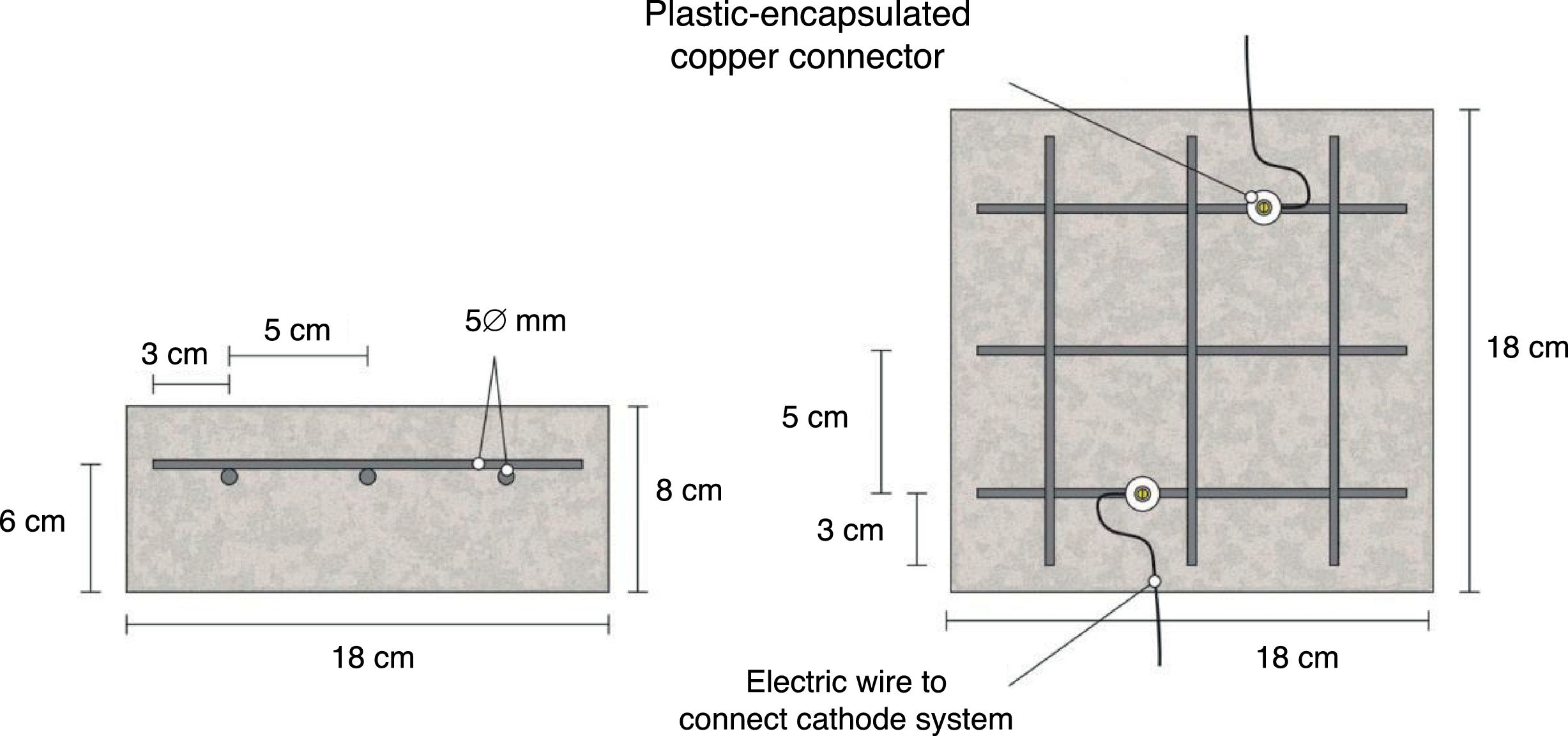
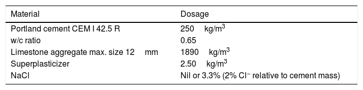
The specimens were prism-shaped reinforced concrete elements, with a dimension of 18×18×8cm3, which were reinforced by a grid 16×16cm2 composed of six steel bars (5mm diameter) welded symmetrically forming squares of 5cm side, and placed 2cm under the anode, Fig. 1. The concrete dosage was as shown in Table 2. Two mixes were prepared: one without added chloride for preparing the specimens intended for pure cathodic prevention (CPre) treatments, and another mix containing 2% Cl− relative to cement mass for the specimens used in cathodic protection (CP) applications or combined treatments (ECE+CP) and (ECE+CPre), see Table 1. Once the formwork was removed, the specimens were moist-cured at 95–98% relative humidity (RH) for 28 days. The characteristics of the hardened concrete were as follows: compressive strength 37.8N/mm2[32], porosity 11.1% [33], and bulk density 2.38 T/m3[34].
.")
Sketch of reinforcement of samples and connection of the cathodic system (steel reinforcement).
Fig. 1 also shows the system used for connecting the reinforcement (cathode system) to the negative pole of the electric power source, through plastic isolated copper connectors screwed to the rebar.
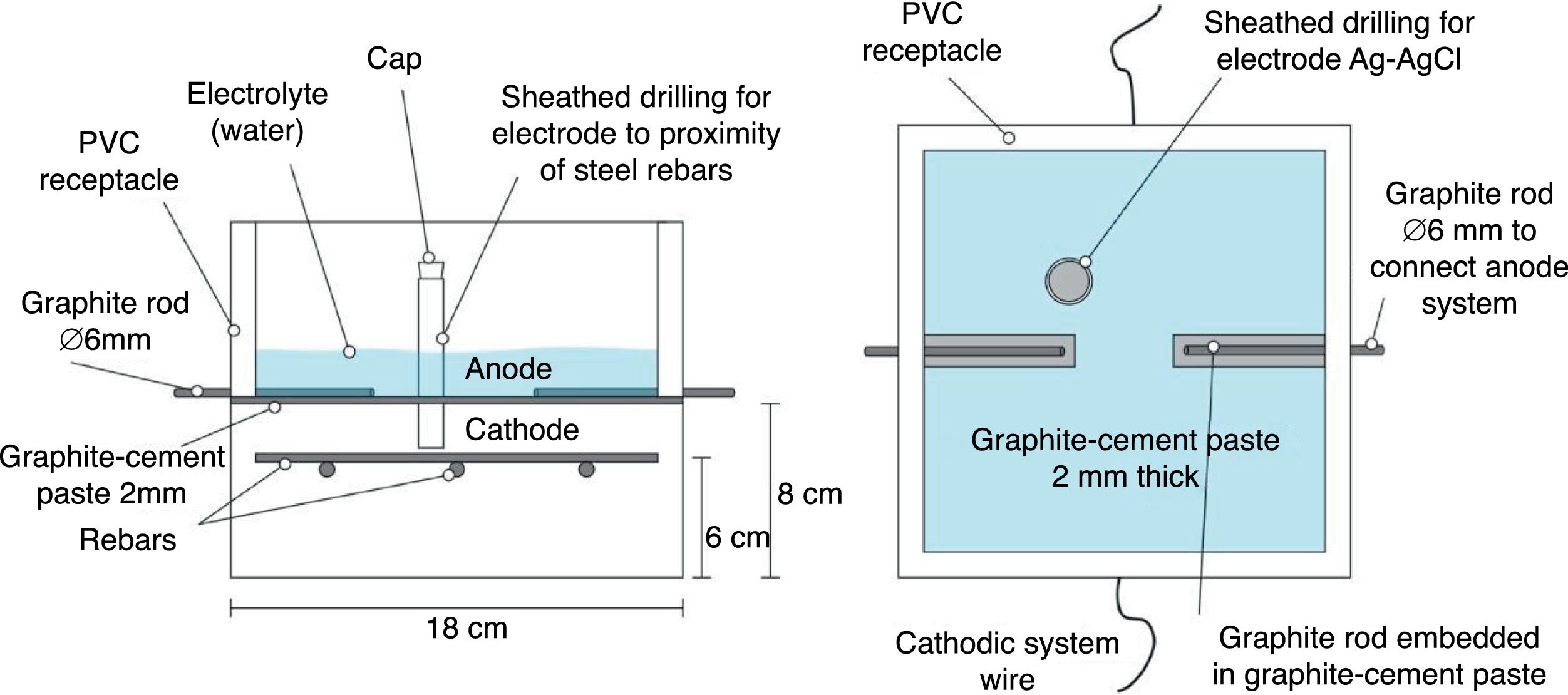
2.2Common experimental details of the electrochemical testsAll the electrochemical tests were performed using a CCP anode. The anodic overlay system was prepared by hardening a graphite–cement paste (GCP) obtained by mixing graphite powder and Portland cement at 50%–50% in mass. Water to solid mix ratio was 0.8. Secondly, a 2mm thick layer of this paste was applied on the surface of each specimen, and then all of them were moist-cured for 10 days. After that, two grooves were performed lengthwise onto the anodic overlay, without reaching the concrete surface, in order to receive both graphite rods to connect to the positive pole of the electric source. To finish up, these rods were overlaid with graphite–cement paste in order to join with the anode system perfectly, but avoiding any contact between graphite rods and concrete. A PVC receptacle was assembled on the top of the samples to retain both ECE electrolyte (distilled water) and/or the dissolution used during CP or CPre applications to simulate a continued chloride contamination (65ml NaCl 0.5M applied weekly), Fig. 2. The ratio between the surface of concrete covered by the anodic overlay and the surface of the primary anodes (graphite rods) was 9.6; the ratio between the surface of concrete covered by the anodic overlay and the total surface of the steel bars was 1.7, Fig. 2. All current density and electric charge density values reported in this work are relative to surface of concrete, (equal to the anode surface), except otherwise stated.

The resistivity of the graphite–cement paste was measured through the four-probe method. To this end, paste specimens were cast in 4×4×16cm3 moulds, and moist-cured at 95–98% RH during 14 days. The experimental details of the measurements can be found elsewhere [35]. The average obtained resistivity was 1.5Ωm.
The measurements of steel corrosion potential (Ecorr) and all the single electrode potentials, were performed using Ag–AgCl reference electrodes. These electrodes were housed in respective holes drilled from the exposed surface of the concrete specimen (that bearing the graphite–cement anode) to the vicinity of the rebar, Fig. 2. For this purpose, the holes were sheathed with a plastic tube, and filled with a KOH 0.2M aqueous solution, trying to approach the physical-chemical conditions of the concrete's inner pore solution.
In this way nine specimens were prepared, seven of them with salt in the mixing water and two without it. Two of the salted specimens were used only for determining the efficiency of the ECE process. Concrete cores were extracted from them, and their chloride content profiles were determined, in one case before and in the other case after ECE. These two specimens were discarded after coring. The seven remaining specimens were intended for the tests corresponding to CP, CPre, and the combined treatments (ECE+CP) and (ECE+CPre), see Table 1.
The ECE efficiencies were calculated as the percentages of reduction of the initial chloride content. Obtaining the chloride content profiles before and after the ECE trials allowed calculating the local and overall efficiencies. At the end of the 24 weeks of exposure to a severe Cl− load, i.e. the first phase of CP and CPre treatments, see Section 2.4, chloride content profiles were obtained from all the reinforced concrete specimens. The Cl− profiles were measured following essentially RILEM recommended procedures [36]. Cylindrical concrete cores, 95mm diameter and 20mm height (up to the rebar depth), were extracted. From these cores, concrete dust samples were obtained by grinding thin (2mm thick) successive parallel layers to the exposed surface [36]. In this way 10 concrete dust samples were gained from each core, thus allowing the obtention of sufficiently detailed chloride content profiles. The determination of the samples’ acid soluble chloride contents was carried out by potentiometric titration [37,38]. All the chloride content values are expressed in this work as % Cl− relative to cement mass.
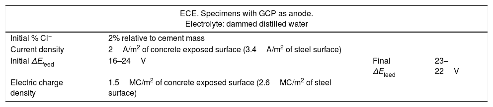
2.3ECE treatmentsFour of the specimens made with saline mixing water were subjected to ECE. For this purpose, the specimens were electrically connected in series by pairs to a direct current source. The relevant parameters of the ECE treatments are shown in Table 3. A low charge density was applied, only 1.5 MC/m2 relative to concrete surface (2.6MC/m2 relative to steel surface). The current source feeding voltage (ΔEfeed) was controlled at a level below 40V during the processes, for safety reasons. It was necessary in this respect to interrupt the current passage two times (two pauses of 24h each one) along the treatment. The whole processes were performed inside a fume hood to eliminate the chlorine, Cl2(g), produced by electrochemical oxidation of the Cl− ions extracted from the concrete. When the ECE processes were finished, the pH values of the electrolytes were measured in order to check the acidifying effect caused by the electrochemical anodic reactions.
Summary of ECE data.
| ECE. Specimens with GCP as anode. Electrolyte: dammed distilled water | |||
|---|---|---|---|
| Initial % Cl− | 2% relative to cement mass | ||
| Current density | 2A/m2 of concrete exposed surface (3.4A/m2 of steel surface) | ||
| Initial ΔEfeed | 16–24V | Final ΔEfeed | 23–22V |
| Electric charge density | 1.5MC/m2 of concrete exposed surface (2.6MC/m2 of steel surface) | ||
This section describes the details of the experiments carried out to demonstrate the applicability of the GCP anodes for combined protective treatments of ECE+CP and ECE+CPre, please refer to Table 1.
The CP treatments were applied with 15mA/m2 of current density (relative to concrete or anode surface) to two specimens, one of those previously treated with ECE (EA in Table 1) and the other one without previous treatment (A in Table 1). On the other hand the application of CPre with 2mA/m2 of current density (relative to concrete surface) to a sample previously ECE treated (EB in Table 1) and to another manufactured without salt and not ECE treated (B in Table 1). The values of the current densities relative to the steel bars surface are 25.5mA/m2 and 3.4mA/m2 for the CP and Cpre treatments, respectively. The direct current source was programmed to maintain a constant current density along the whole processes. Each application has its reference sample without treatment of CP or CPre to compare the results. The reference sample for the specimens subjected to combined treatments (EA for ECE+CP, and EB for ECE+CPre) is ER. R is the reference for A, and P is the reference for B.
The application of CP and CPre consisted of two phases:
Phase 1. First 24 weeks. The aforementioned treatments CP and CPre were continuously applied during the first 13 weeks. Then, the current was switched off for 4 weeks and after that, treatments were resumed to the end. Chloride contamination was continuously applied, even during the switch off periods.
While applying the CP and CPre treatments some electrochemical parameters were measured. During the current passing periods the feeding voltage of each specimen, ΔEfeed, was obtained as the potential difference between cathode and anode; and the individual anodic and cathodic potentials, Ea and Ec, respectively, were measured against the reference electrode Ag–AgCl. Finally, in order to check the efficiency of CP and CPre as maintainers of protection conditions of steel, the “100mV decay” criterion was used, as is specified in ISO 12696:2012 [39]. This criterion has been also extensively employed for this purpose by several researchers [21,40]. The method consists in obtaining the 4h potential decay (ΔEdecay), that is the difference between Ec4h (the value of Ec 4h after the current switch off), and the instant-off cathodic potential Ecio, which in this case was measured 1s after the current switch off. The minimum value of the 4h depolarization must be 100mV for an adequate corrosion protection of steel [39]. The values of Ecio were monitored with an automatic data logger able to obtain and record 500 measurements in 6s, after the current switch off.
Once the 24 weeks processes were fulfilled, cores were extracted from all specimens of Table 1, and their respective Cl− content profiles were obtained. This was done with the purpose of evaluating the net effect of the electrochemical treatments on the Cl− ion uptake by the reinforced concrete specimens during the continued exposure to a very aggressive environment.
Phase 2. At the end of Phase 1 it was observed that all the specimens had lost the steel protection condition, evidenced by ΔEdecay values lower than 100mV. Then, it was decided to start this second phase with the objective of recovering the protection conditions of steel by adjusting the current density of the CP treatments. The procedure was to increase progressively the current density during 4 weeks, starting with a value of 20mA/m2, until obtaining the protection conditions.
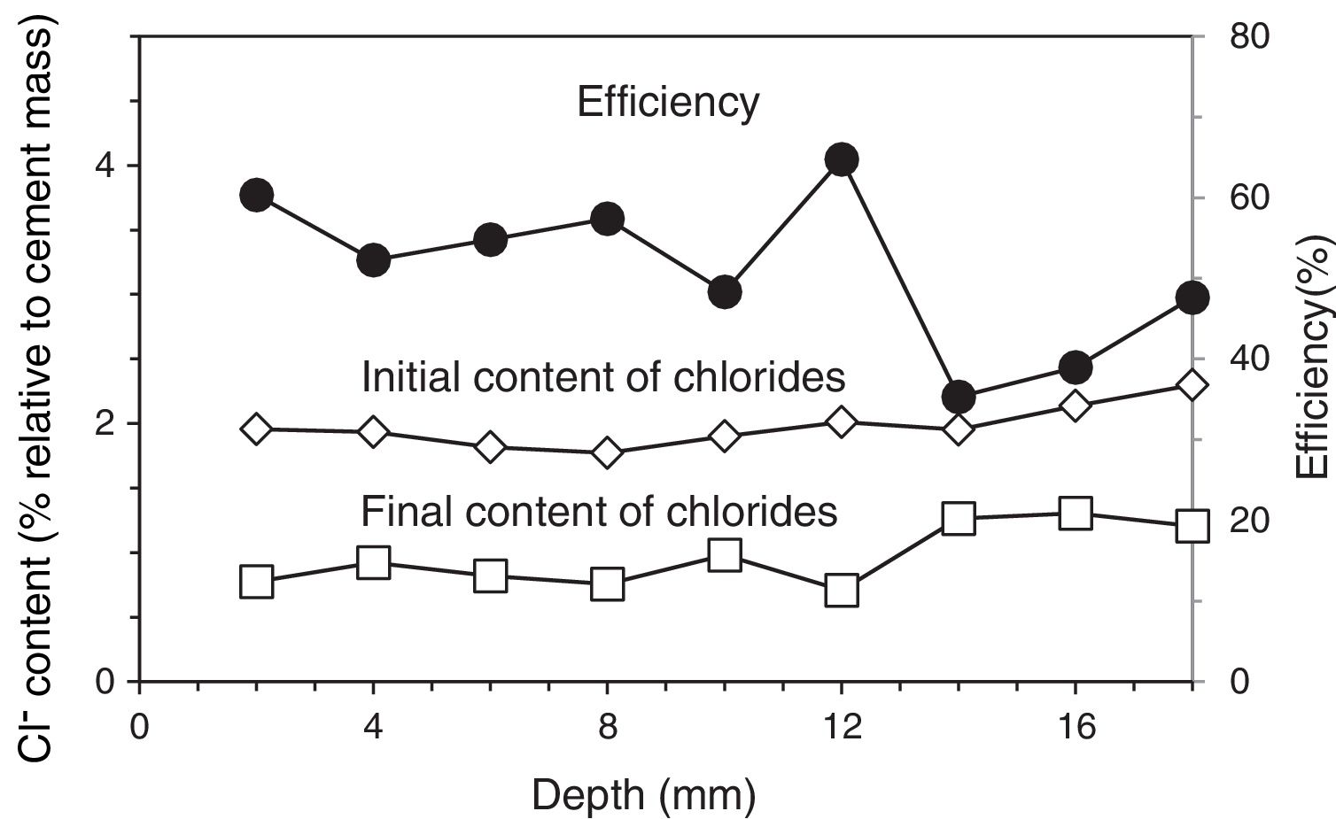
3Results and discussion3.1Application of ECEFour of the reinforced concrete specimens were subjected to an ECE treatment before starting the first phase of the CP and CPre treatments, see Section 2.3. Once finished the ECE process with the settled parameters, Cl− content profiles were obtained, corresponding to the states before and after the ECE treatment. The local ECE efficiencies, understood as percentage of Cl− content removed, are plotted in Fig. 3. The average of removed Cl− was 51% of the initial content, i.e. the residual Cl− content of concrete after ECE was approximately 1% referred to cement mass. This indicates a good performance of the ECE process applied on a conventional ordinary Portland cement concrete with the GCP anodic overlay system, for a relatively low charge density of 1.5×10⁶C/m2 relative to concrete surface. This result can be compared to the 41% efficiency obtained for a very similar reinforced concrete element, with the same initial amount of Cl−, subject to an ECE treatment, using a Ti–RuO2 mesh anode, and passing a total charge density of 1MC/m2 relative to concrete surface [26].
 and after ECE (final), and local efficiencies of the extraction process. ECE details: current density: 2A/m2, charge density: 1.5MC/m2, both related to exposed concrete surface.")
Chloride concentration profiles before ECE (initial) and after ECE (final), and local efficiencies of the extraction process. ECE details: current density: 2A/m2, charge density: 1.5MC/m2, both related to exposed concrete surface.
The pH values determined for the electrolytes, after the ECE experiments, were in the range 5–5.5. This means that the acidity of the electrolytes had increased slightly, (the initial electrolyte was distilled water). This acidifying effect may be due to several of the electrochemical anodic reactions, namely the oxidation of hydroxide ions or water to O2(g) and the oxidation of carbon to CO2(g). It is possible that the alkaline character of the graphite–cement paste anode may have reduced the acidity produced by those electrochemical processes. It is worth noting that no sharp increase of the feeding voltage was observed during the ECE treatments. This suggests that no important damage of the GCP overlay has been produced during ECE [21], even though these trials are performed with a high current density of 2A/m2. We must recall that the ECE trials are performed under continuous liquid ponding of the anode, and its duration is short, about eight days.
3.2First phase of CP and CPre treatmentsIn this section we describe the results of tests carried out to investigate the performance of the GCP anodes during protective electrochemical treatments to reinforced concrete elements affected by steel corrosion due to chloride contamination, such are CP, CPre and combined treatments of ECE+CP or ECE+CPre, see Table 1.
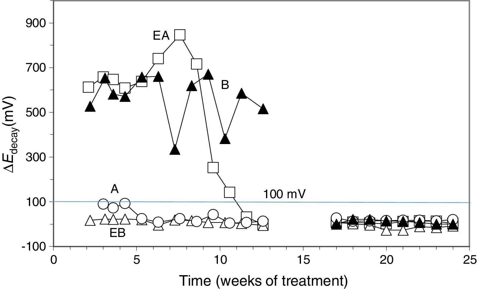
To verify the effectiveness of CP and CPre treatments for protecting steel from corrosion, the “100mV decay” criterion [39] was used, as stated in Section 2.4. Fig. 4 shows the evolution of the ΔEdecay values for the specimens in Table 1, during the 24 weeks experiments. The ΔEdecay values of the A specimen, treated only with CP, practically never reached the threshold value of 100mV. It seems that a 15mA/m2 current density was not sufficient to provide protection to steel in such harsh conditions: initial Cl− content of 2% plus the continued salting regime (65ml NaCl 0.5M weekly sprayed onto the anodic overlay surface). Regarding the EA specimen (ECE+CP), the protection conditions of steel were kept during 11 weeks because of the current circulation, despite external Cl− loading. Cathodic protection of 15mA/m2 current density, relative to concrete surface, was able to keep protective conditions for the steel reinforcement if the initial Cl− content of the specimen was about 1% (EA). In the case of the specimen with initial Cl− content of about 2% (A), a higher current density would be needed for reaching the protection conditions [9,11]. These observations corroborate the main hypothesis of the present research, i.e. in cases of reinforced concrete structures with a high Cl− contamination subject to very harsh chloride environments, it would be advantageous to apply successively an initial ECE treatment to reduce the Cl− content, and then maintain protective conditions to steel through a continuous CP treatment without the need of using a too high CP current density, which could eventually impair the performance of the anodic system [21]. These combined treatments, ECE+CP, would be more conveniently implemented with the CCP coatings, since the same anode can serve both for the ECE and for the CP treatments.

Evolution of ΔEdecay during the CP or CPre treatments. A: CP; B: CPre; EA: ECE+CP; EB: ECE+CPre. All of them subjected to Cl− contamination during the 24 weeks. The electrochemical treatments were interrupted between week 13 and week 17.
Regarding the CPre treated specimens (cathodic current density 2mA/m2 relative to concrete surface), specimen B showed ΔEdecay values higher than 100mV up to the current switch off at 13th week, confirming the capacity of continuously applied CPre treatments to keep steel protection conditions for an initially Cl− free reinforced concrete, despite extensive external Cl− load [9,11,41,42]. On the other hand such a low current density is unable to protect steel if concrete is previously contaminated at a level of about 1% relative to cement mass, and steel has started to corrode, as shown for specimen EB (ECE+CPre) in Fig. 4.
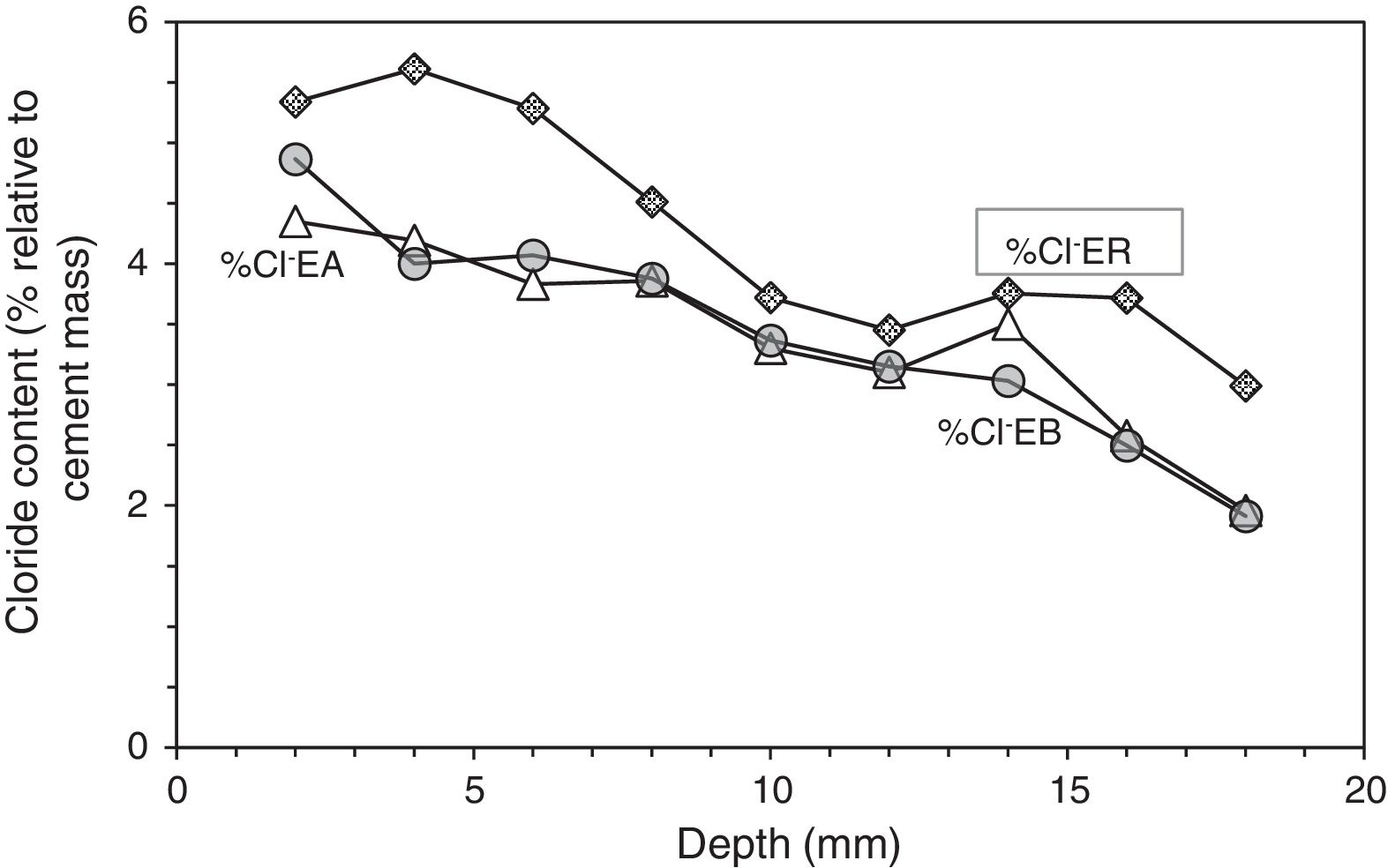
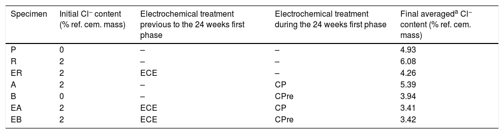
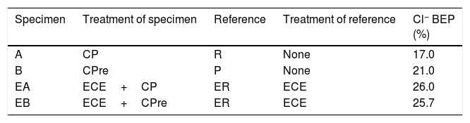
At the end of Phase 1 all the reinforced concrete specimens had reached a very high degree of Cl− contamination, as can be appreciated in Table 4. Nevertheless, some comparisons can be done on the behaviour of the different cases. For instance, Fig. 5 shows that the specimens treated with ECE+CP (EA) or ECE+CPre (EB) during Phase 1, have experienced less Cl− ingress than the reference specimen ER, which after the ECE trial was left untreated during the Phase 1. This represents a further evidence of the “chloride barrier effect”, mentioned by Pedeferri [9], as one of the beneficial secondary effects of CP, as the polarity of the electric field induces a repellent effect of the negative ions, thus reducing the chloride uptake by concrete. The effect can be quantified by using a Cl− barrier effect parameter (Cl− BEP), which is defined here as the percentage of reduction of the Cl− uptake by concrete, due to CP or CPre actions, referred to the Cl− uptake of the reference, (not treated) specimens, see Eq. (1).

Final averaged chloride contents (expressed in % Cl− relative to cement mass) at the end of the 24 weeks of exposure to a severe Cl− load (first phase of CP and CPre treatments).
| Specimen | Initial Cl− content (% ref. cem. mass) | Electrochemical treatment previous to the 24 weeks first phase | Electrochemical treatment during the 24 weeks first phase | Final averageda Cl− content (% ref. cem. mass) |
|---|---|---|---|---|
| P | 0 | – | – | 4.93 |
| R | 2 | – | – | 6.08 |
| ER | 2 | ECE | – | 4.26 |
| A | 2 | – | CP | 5.39 |
| B | 0 | – | CPre | 3.94 |
| EA | 2 | ECE | CP | 3.41 |
| EB | 2 | ECE | CPre | 3.42 |
, with ECE and after CPre (EB), and in the reference sample only treated with ECE (ER), all of them subjected to Cl− contamination process, after ECE and first phase of CP or CPre (24 weeks).")
Profiles of Cl− content in specimens treated previously with ECE and after with CP (EA), with ECE and after CPre (EB), and in the reference sample only treated with ECE (ER), all of them subjected to Cl− contamination process, after ECE and first phase of CP or CPre (24 weeks).
Table 5 shows the net values of the Cl− barrier effect parameter found for the specimens tested in this work, putting in evidence that this parameter reaches values of about 20% in the experimental conditions of this work.
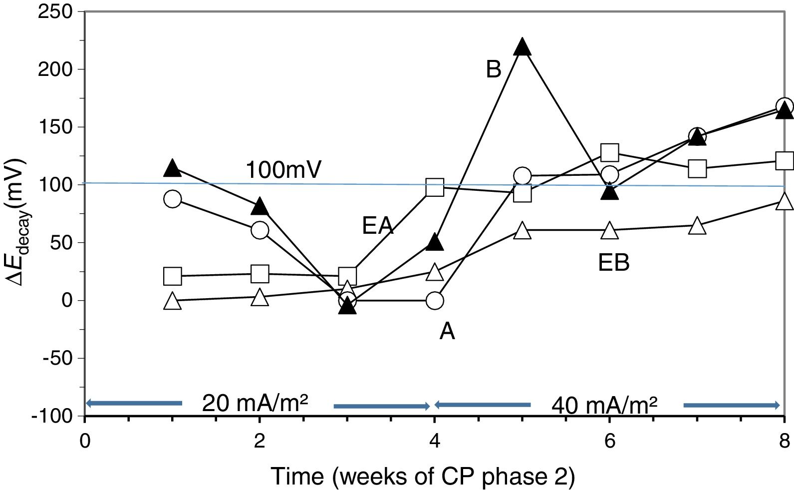
3.3Second phase of CP treatmentsGiven that after the 24 weeks of treatments of Phase 1, including rest periods between the 13th and 17th weeks, the steel reinforcements in all concrete specimens had completely lost their protection conditions, and having been demonstrated that a CP of 15mA/m2 was unable to restore the protective conditions (Fig. 4), the Phase 2 was started. The external Cl− load was discontinued since all the specimens had reached very high Cl− contents, see Table 4. In these conditions, CP was applied with higher current densities. The question was if it would be possible to recover the protection conditions of steel by increasing the current density to the appropriate value. In the beginning of this last phase, the current density was set at 20mA/m2. After 4 weeks in operation the threshold value of 100mV ΔEdecay was not reached, i.e. the protection conditions were not obtained, Fig. 6. Neither success was obtained in a second attempt at 25mA/m2 (data not shown in Fig. 6). Finally, a third step of 40mA/m2 was set. In this case, after 4 weeks, the rule of 100mV of ΔEdecay was achieved for EA, A and B specimens.

Evolution of ΔEdecay during Phase 2 of CP. First step of 4 weeks with 20mA/m2 of current density, and third step with 40mA/m2. Specimens A, B, EA and EB.
Moreover, protection conditions were verified with the measurement of depolarization potential difference values 7 days after switch off [39]. In fact, more than 150mV of ΔEdecay was reached after 7 days (209mV for EA, 211mV for A and 153mV for B). This efficiency of CP is similar to that obtained by other researchers [40,43]. However, this was not the case for EB. After 4 weeks with a cathodic current density of 40mA/m2 the protection conditions were not recovered for this latter specimen.
4ConclusionsThe results of this work point out that it is possible to use a graphite–cement paste, overlaid on the surface of a reinforced concrete element, as the anode for successive treatments of electrochemical chloride extraction, to reduce the chloride content, and then cathodic protection to maintain protective conditions for the steel reinforcement. The following aspects can be emphasized, namely:
- •
The application of ECE, in the experimental conditions of this work, does not seem to produce damage of the GCP anodes, which could impair the performance of the anodic system in the posterior continuous CP treatment.
- •
The chloride barrier effect parameter (Cl− BEP) is defined as the percentage of reduction of the Cl− uptake by concrete, due to CP or CPre actions, referred to the Cl− uptake of the reference (not treated) specimens. This parameter allows evaluating the magnitude of the chloride barrier effect due to the application of CP or CPre to reinforced concrete elements continuously exposed to a harsh chloride environment. The found values of this parameter, both for simple CP or CPre trials and for the combined treatments of ECE+CP, are about 20%, in the experimental conditions of this work.
- •
A cathodic current density of 2mA/m2, typical of CPre applications, is unable to protect steel after an ECE treatment.
- •
It is possible to recover protective conditions against corrosion of steel reinforcement in concrete by applying a combined treatment of ECE followed by a continuous CP treatment. The current density value of the CP step must be set at the proper value, according to the residual chloride content in concrete. The needed CP current density value will be lower than if the ECE was not applied, thus reducing the risk of damage of the anode. In this sense the GCP overlays on concrete may show an advantageous versatility, over other types of anodic systems, since the same anode is used on the two steps of the combined treatment.
This research was funded by the Spanish Agencia Estatal de Investigación (AEI), and Fondo Europeo de Desarrollo Regional (FEDER) through project BIA2016-80982-R. We acknowledge also funding from the Spanish Ministerio de Ciencia e Innovación (MAT2009-10866), and Generalitat Valenciana (PROMETEO/2013/035).
The authors would like to dedicate this work to honour our master and friend Prof. Carmen Andrade Pérdrix, who suggested our research group undertaking research on the application of electrochemical techniques to reinforced concrete structures.