


Advances in computational tools for welding process simulation have been noteworthy, allowing to assess complex phenomena, as is the case of welding distortion and residual stress. The most advanced tools take into account the thermo-metallurgical and thermo-mechanical changes that take place during the welding processes. Considering these changes and the materials properties at the different temperature values, it is possible to obtain reliable models of the welding processes. In this communication, T-joint welded configurations are investigated, considering arc welding and laser beam welding processes. For this purpose, the commercial software ESI SYSWELD was adopted, since it is one of the most advanced tools for this purpose. These models are based on finite elements; therefore, a mesh sensitivity analysis was performed in order to evaluate the minimum element size required for accurate results. In arc welded double side T-joint, different procedures were explored in order to understand the influence in the residual stress; the second pass does not increase the maximum residual stress, however it increases the area with tensile residual stress. Results for a T-joint between a steel tube and a steel plate using laser beam welding (LBW) and arc welding were obtained. The laser beam welds presented a significant reduction of the heated affected zone and, consequently, the tensile residual stresses are confined to a smaller area.
An earlier paper by the present authors gave details of the simulation, using SYSWELD, of laser beam welded (LBW) butt joints of thin Al alloy plates [1]. On the basis of that experience, further work was developed on the simulation of more complex situations as T-joints or the connection of plates and tubes. Unlike generic finite element method (FEM) commercial codes as ABAQUS or ANSYS, FEM software packages to model the specific problems encountered in welding are far less widely used, and therefore the objective of the present paper is to document the use of SYSWELD in modelling complex welding situations.
The non-uniform thermal expansion resulting from welding processes causes distortions and residual stresses. Distortion, residual stresses and clamping are inter-related; high clamping involves high residual stresses and eventually low distortion, whereas light clamping is associated to large distortion and lower residual stresses, see e.g. [2]. Many efforts are made to control these phenomena, of great economic and industrial relevance. The decrease in weight of stiffened panels and structures may be achieved using stronger materials and thinner cross sections. Costs involved in maintaining dimensional accuracy during fabrication and subsequent construction, including special processing procedures, straightening and rework, may represent approximately 30% of the fabrication costs in shipbuilding [3–5].
Welding distortions may be predicted using the finite element method. SYSWELD simulates the physical phenomena occurring in the welding process with thermal analysis based on transient thermal conduction model. Different welding processes use different heat sources. Goldak's double ellipsoid heat source [6] is typical for welding processes such as electric arc, MIG and TIG. Beam sources are used in high energy welding processes characterized by a Gaussian temperature distribution.
Trial and error approaches to distortion management and residual stress evaluation are inefficient and costly. Important savings can be obtained using finite element (FE) analyses that reduce lead time, process planning costs, and the need for experimentation. Those analyses represent a planning tool to be used prior to the actual welding process and concurrently with design.
In the round robin programme of the International Institute of Welding (IIW) comparing computed and experimentally measured residual stresses, SYSWELD was mainly used for modelling the heat input from the welding process whereas the kinematic hardening model was recommended for modelling the deformation behaviour [7]. ESI software for welding engineering includes SYSWELD, for simulation of heat treatment and weld quality including all physics, in particular phase transformation and mechanics, and WELD PLANNER for fast distortion analysis based on a shrinkage method, including pre-processing, solver and basic post-processing [8].
1.1FEM tools and benchmarkingCasalino and Mortello [9] may be mentioned as an example of welding FEM analysis using general purpose codes. In this case ANSYS was used for FE modelling of butt configuration of fibre laser beam welding of Ti6Al4V. The parametric design language of ANSYS (APDL) was used for the generation of the numerical code, and the calibration of the model involved cross-section geometry and thermal cycle close the weld seam. The thermal contact conductance at the interface was simulated to improve accuracy. Transient temperatures and geometric characteristics of the weld zone were calculated. Good agreement was found between numerical and experimental results.
Deshpande et al. [10] give an example of FEM analysis using ABAQUS in conjunction with SYSWELD. Butt joint welding and post weld heat treatment simulations of two Inconel 718 plates were studied. SYSWELD was found to be slightly faster than ABAQUS. As a general purpose FEM software, for these analyses ABAQUS requires the writing of user subroutines for welding simulation such as heat source geometry definitions, moving heat source functions, heat treatment analyses and thermo-chemical treatments, whereas all these features are available in SYSWELD. SYSWELD seems to present lower lead time than ABAQUS for process modelling and can be considered as an alternative to ABAQUS for complex welding simulations such as for aero-engine structures. However, according to Deshpande et al. [10], even for experienced FEM analysts the use of SYSWELD requires extensive training and specific user's experience.
The ESI ‘End user license’ stipulates that (quoting) ‘no scientific or academic publication nor any other publication or communication to third parties of benchmark results is permitted without the prior written authorization of the Software Publisher. This applies every time such publication or communication contains a comparison between different computer programmes […]’. The above mentioned work, [10], constitutes therefore an opportunity for finding in the open literature benchmarking of these simulation tools.
In another paper, Deshpande et al. [11] discuss FE simulation of welding processes and prediction of component distortions. Tungsten inert gas welding was modelled using SYSWELD for a butt joint between 2mm thick sheets of stainless steel 304. A 3D double ellipsoid heat source was used to model the heat flow during welding. The distortion for an unclamped situation predicted using FE is compared with the result of an experimental trial. The experimental results and FE predictions of fusion zone, thermal histories, and residual distortion were found to be in reasonably good agreement. The validated FE methodology was also used to perform a parametric study on the effect on distortion of natural and forced cooling, clamp release times, and welding sequence.
Chen and Guedes Soares [12] also used ANSYS in a study of stiffened plates. User-defined macros were created using the ANSYS APDL to model the moving heat source, considering the double ellipsoidal model.
Combinations of software tools may be necessary to deal with increasingly complex and integrated problems as exemplified by the replacement of the traditional bolted connection of the ring gear and differential case in the power train of an automobile using laser welding, studied by Yu et al. [13]. That welding process was suggested to save space and reduce weight, manufacturing cost and part count. The high carbon content of cast iron and carburized steel is a source of difficulties for welding. In this case laser beam welding using Ni-base filler metal was used, and the results satisfied the torsional stiffness and durability requirements; nevertheless, in comparison with the bolted connection method, noise and hardness problems occurred. These problems were solved reducing the penetration depth and the carburized layer of the ring gear. Welding deformation, torsional stiffness and fatigue were modelled using computer simulation, avoiding expensive experimentation. The effect of the reduced penetration depth and removal of the carburization layer was evaluated using SYSWELD. NX NASTRAN was used to predict the stiffness and strength according to the change of the weld penetration depth. FEMFAT, a fatigue analysis software, was used to model the torsional stiffness and fatigue life. This work has demonstrated the possibility that laser welding could substitute the conventional bolted connection as joining process of the ring gear and differential case.
In a work on the crack compliance method of residual stress measurement, Urriolagoitia-Sosa et al. [14] mention that it has been intended to find among ABAQUS, ADINA, ANSYS, FEMLAB, MSC MARC, and SYSWELD, the software giving best results. Such codes are in a continuous process for quality improvement and it is well known that the algorithms involved are carefully validated. Therefore, it was considered that the procedures involved in the finite element analysis have already been accepted, and so the research was focused only on the comparison of diverse solutions. Instead, the authors used an in-house FE software to compare numerical residual stress results with experimental results of the crack compliance method. Finally, no benchmark of FE packages is therefore presented in [14].
1.2Aims of the analysesAn obvious application of welding simulation using finite elements is the optimization of process parameters. This is exemplified in Yu et al. [15] who comment that as oil and gas pipelines develop towards high pressure and large throughput, greater attention has been dedicated to welding quality of oil pipelines. Large-diameter welded pipes are typically manufactured using submerged arc welding, and pipeline safety relies on welding quality. A SYSWELD FE model was used for microstructure and residual stress analysis in the weld zone of multiwire longitudinal submerged arc welding, whilst experiments were carried out to obtain welding temperature field with relatively high accuracy. Concerning residual stress versus preheat temperatures, residual stress decreased with increasing preheat temperature up to 100°C, meanwhile content of bainite in microstructure decreased, thus facilitating reduction in residual stress. This SYSWELD based study provides quantitative reference for further optimization of welding parameters and improvement in weld mechanical properties.
Further to the obvious aim – to predict behaviour without costly physical experimentation - the integrated simulation of the manufacturing process leads to advances in structural integrity assurance during the life cycle. That is the case for example in the prediction of the fatigue crack growth behaviour of welded stiffened panels manufactured with Al alloys, where pre-existing residual stress field must be taken into consideration, see e.g. Tavares et al, [16,17]. In the shipbuilding area, the increasing use of lightweight Aluminium structures raises the need to include the effects of welding in structural components in order to understand structural response, see e.g. Fisher and Nahshon [18]. In a different field, Papadakis et al. [19] studied the simulation of the crash behaviour of whole automotive body structures, a subject of increasing value in the development phase of the overall product cycle in the recent years.
1.3Properties databaseTemperature-dependent physical and mechanical properties are required for FE analyses. ESI software includes an extensive database, illustrated e.g. in Manurung et al. [20] and Leitner et al. [21]. The SYSWELD properties database is well illustrated in Hildebrand et al. [22], namely effect of heat treatment (on density, specific heat per unit of mass, thermal conductivity), as well as metallurgical phase diagrams, Poisson's ratio versus temperature relationship, stress–strain curves for various temperatures, yield strength versus temperature in different phases, temperature dependent Young's modulus, and thermal expansion coefficient for different phases.
1.4Amount of time necessary to perform the analysis, and accuracyIt was mentioned before that Deshpande et al. [10] state that, even for experienced FEM analysts, the use of SYSWELD requires extensive training and user's experience. In another study, the authors – Perret et al. [23] – considered that a time frame of 4–6 weeks to achieve results was reasonable for an industrial application of welding simulation without prior expert knowledge in welding simulation. In the context of [24], 3D analyses may take approximately 100 times longer than 2D analyses [24]: computational time of 2D FEM was extremely faster (15–20min) compared to 3D FEM (24–30h). Wang et al. [25] note that while angular distortion can be accurately predicted using a coupled 3D FE model, computational times can be on the order of days for medium and large weldments, a time frame that often hinders the use of FE-analysis in engineering work.
Simulation and experimental data concerning a welded assembly from the automotive industry were compared in Perret et al. [23]. Temperature fields and transient distortion distributions were measured with thermocouples and with an optical 3D deformations analysis tool, respectively. The simulated temperature fields were found to accurately match the numerical ones. Qualitatively, the simulated distortions also agree with the experimental ones. Quantitatively, a difference of approximately 20% between the simulated and the measured distortions was found, a discrepancy deemed acceptable taking into account the simplifications and assumptions involved in the simulation. The global time to solution to get these results without expert knowledge in welding simulation was 4–6 weeks.
According to Siegele [26], numerical methods are nowadays a useful tool for the calculation of distortion and residual stresses resulting from the welding process. Deformations and stresses due to the welding process and taking into account the change of microstructure due to different heating and cooling rates may be calculated using modern FE software. Further to the welding simulation per se, welding mechanics combines the mechanics and the material behaviour from the welding process with the assessment of service behaviour of welded components.
As an example, Veneziano et al. discuss in [27] the welded roof profile and B-pillar of the Audi A2 spaceframe, consisting of a hydroformed AlMgSi0.5 (AW 6060) extrusion profile and a Aural-2 die-cast B-pillar. A laser welding process was applied using AlSi12 consumables without post-weld heat treatment. SYSWELD was used or the numerical simulations, aiming at prediction of residual stresses and distortion. Conclusions of the study were (i) increasing clamping time during cooling contributes to smaller distortions and relaxation of residual stresses, (ii) increasing the number of welding steps implies greater complexity for the prediction of residual stresses and distortions since subsequent welds have great influence on residual stress and distortion created by previous ones (iv) modelling complex welds involves weld simulation and elastic-plastic deformation analysis of partially welded components.
1.5T-jointsT-joints were simulated in the present work. They are an important welding configuration, specifically studied, e.g. by Manurung et al. [20].
Temperature distribution, weld induced distortion, and residual stress in stiffened plates were investigated experimentally and numerically by Chen et al. [12]. The welding process was simulated using a non-linear thermo-elasto-plastic approach, and good agreement was found between the experimental measurements and the obtained temperature distribution and vertical deformation. Especially in the thicker plates, obvious differences of residual stresses were observed throughout the plate thickness direction. It was concluded that the welding sequence has a significant effect on the welding induced plate distortion and on the longitudinal stress distribution mainly in the lower layer of the plates. Two short welding passes from the middle to the edges are preferable in the industrial fabrications since it results in smaller distortion and residual stress.
A key feature in welding numerical simulation is the modelling of a moving heat source. User-defined macros were created in the study using the ANSYS APDL to model the moving heat source, considering the double ellipsoidal model.
Doyen et al. [28] highlight the high calculation times needed for a large and complex structural component which implies to set up a simplified welding simulation method. The study was composed of several phases, starting with an experimental and numerical study of a T-joint fillet mock-up GTAW used to develop the preliminary welding procedure and to validate a simplified simulation method.
T-joints are considered one of the most common welded joints used in the construction of offshore structures, including ships and platforms, Fu et al. [29]. A sequentially coupled thermo-mechanical FE model considering temperature-dependent material properties, high temperature effects and a moving volumetric heat source was used to investigate the effect of welding sequence on the residual stresses and distortions in T-joint welds. Again, the results show that residual stresses and distortions, both in the magnitude and distribution mode strongly depend upon the welding sequences.
Further studies on T-joints may be mentioned. Leitner et al. [21] model stiffeners, whereas Sulaiman et al. [30] study specifically the T joint. Using FE methods, Lidam et al. [24] studied the angular distortion in the multipass GMAW process on combined butt and T-joint. SYSWELD was capable of simulating the multipass welding process and can be used to predict the angular distortion on combined butt and T-joints. The analysis generated relevant information which can be used prior to designing and as a planning tool before the actual welding process. It was concluded that welding sequence should be investigated further in order to characterize the effect of the sequence on the angular distortion of the complex structure.
2Case studies2.1Mesh sensitivity analysisSYSWELD enables the coupled modelling of complex physical phenomena such as electromagnetism, heat transfer, diffusion and precipitations of chemical elements, phase transformations and mechanics. It is compute-intensive if the number of system variables (elements and nodes) is high: processing time significantly increases with increasing mesh size. Furthermore, the model size is limited to the available volatile memory. Due to these circumstances, a mesh sensitivity analysis was performed, evaluating different mesh refinements and types of elements in order to measure the computational time and eventual differences in the results.
This first analysis is based on the classical example of a T-joint with a single arc welding pass. Fig. 1a presents the geometry and segmented areas for mesh definition.

This T-joint is composed of a 10mm thick bottom plate 120mm wide and a vertical plate with the same thickness and 70mm width, both of construction steel S355. The filler material considered is also the same S355 steel.
This model has 200mm length, representative of a long weld since the steady state is achieved after 50mm of weld.
The mesh near the welding area was refined and three different types of elements were considered: full tetrahedral; full hexahedral and hybrid hexa-tetrahedral elements. Three element sizes were considered: 0.5, 1 and 1.5mm, resulting into 27 SYSWELD models. A workstation with Intel Xeon processor (E5-2620 v3) and 16GB of RAM was used. As an example, Fig. 1b shows a hexahedral mesh with an element size of 1.5mm. The welding heat source for this case has a double-ellipsoid with 17mm length and 8.5mm width. Heat sources between 1000 and 1500J/mm of energy, with efficiencies between 70% and 80% and penetrations between 3 and 4mm were used, after model calibration in order to obtain similar results for all models. The welding speed was 6mm/s, corresponding to 33.3s of welding for this model. Additionally the models take into account the cooling process, 120s considering free air cooling at room temperature (20°C); details of the simulations may be found in Ramos [31].
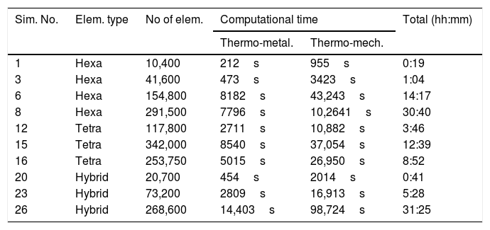
A summary of the model size and the computational time for selected simulations, considering the thermo-metallurgical and thermo-mechanical sub-steps is presented in Table 1. As expected, the computational time increases significantly with the number of elements. The tetrahedral elements were the most efficient in computational terms, mainly due to their reduced number of Gauss points.
Model characteristics and respective computational time.
| Sim. No. | Elem. type | No of elem. | Computational time | Total (hh:mm) | |
|---|---|---|---|---|---|
| Thermo-metal. | Thermo-mech. | ||||
| 1 | Hexa | 10,400 | 212s | 955s | 0:19 |
| 3 | Hexa | 41,600 | 473s | 3423s | 1:04 |
| 6 | Hexa | 154,800 | 8182s | 43,243s | 14:17 |
| 8 | Hexa | 291,500 | 7796s | 10,2641s | 30:40 |
| 12 | Tetra | 117,800 | 2711s | 10,882s | 3:46 |
| 15 | Tetra | 342,000 | 8540s | 37,054s | 12:39 |
| 16 | Tetra | 253,750 | 5015s | 26,950s | 8:52 |
| 20 | Hybrid | 20,700 | 454s | 2014s | 0:41 |
| 23 | Hybrid | 73,200 | 2809s | 16,913s | 5:28 |
| 26 | Hybrid | 268,600 | 14,403s | 98,724s | 31:25 |
Differences are noticed between these simulations. Fig. 2 presents the residual stress profiles for a transversal and for a longitudinal line, for three simulations with hybrid mesh and element size of 1.5mm (simulation #20), 1mm (simulation #23) and 0.5mm (simulation #26). Maximum longitudinal residual stress is identical for the three models. However, in the welding zone a refined profile of the residual stress field is obtained with smaller element size, which for detailed strength examinations might be relevant, but for distortion analysis the differences are negligible.
2.2Double pass T-joint
A double pass T-joint configuration was investigated aiming to understand the impact of the second weld in residual stress field and distortion. Fig. 3 shows schematically the model geometry and boundary conditions. The bottom and vertical parts are completely constrained, and the material considered was also the S355 construction steel. Dimensions including tested welding length were as in the mesh sensitivity analysis presented above. Energy input of 1500J/mm with a efficiency of 70% and a penetration of 3.5mm were considered for both welds. Furthermore, the welding speed for both welds was 6mm/s and a dwelling time of 0.7s were considered between the two passes. As before, 120s cooling after welding during was considered.

A hybrid mesh with tetrahedral and hexahedral elements, with an element size of 1mm, was used, on the basis of the conclusions of the previous study. The model was composed of 68,200 elements.
The same workstation as the one used for the previous study was used, taking nearly 83h to complete the simulation. The simulation of first and second welds takes nearly the same processing time.
Fig. 4 presents examples results obtained. From the von Mises contour map of the residual stress field, Fig. 4a, a maximum tensile stress of about 650MPa is found in the bottom part of the welding seam, as expected. The normalized distortion shows the torsion of the top of the T due to the second welding, an expected behaviour in this type of T-joint weld.

Residual stress differences between the single and double pass T-joint weld were assessed. Fig. 5 shows the residual stress field along the same line considered in Fig. 2 for the longitudinal stress; for the transverse direction a line behind the welding seam was considered. From these results it is noticed that the second welding pass does not significantly increase the welding peak in the longitudinal direction. However, in the transversal direction, a significant difference between both passes was found, the second welding pass the being more important for the final result since the first pass suffers a significant reduction due to the heat ‘treatment’ instigated by the second pass, Fig. 5b.
2.3Heat exchanger joint
Heat exchangers employ considerable amounts of welding, the reduction of distortion being fundamental to avoid further post-processing to unbend the part. In this case, laser beam welding was tested to verify the type of distortion obtained and to quantify the residual stress field.
The part tested in an assembly of tubes and plates that are welded. Fig. 6a shows the geometry of this parts. The tubes have 76mm diameter and are 4mm thick. The plates have 50mm width and a thickness of 10mm. The part model considered a weld of 200mm length, representative of the joint. Fig. 6b presents the mesh and boundary conditions used in SYSWELD. The material of both parts is a S355 steel and filler material was not considered. The welding speed is 60mm/s, corresponding to a 3.33s of welding time for 200mm weld length. In this case, the heat source used was conical due to the high energy density of the laser process. Dimensions of this heat source are 2mm for the top diameter and 1mm for the bottom diameter for a penetration of 3mm. These dimension were obtained from a cross section of a performed weld [31]. The input energy of the laser beam is 167J/mm and it is considered an efficiency of 100%. Welding cooling was also modelled during 60s, considering free air cooling at room temperature (20°C).

This model is composed by 322,200 elements and takes about 174h of processing time in the same workstation detailed in Section 2.1.
Fig. 7 shows the results obtained for the residual stress field and the deformation. As expected the residual stress field is confined to a small area.

The laser beam is a concentrated heat source, permitting high speed and very low distortion of the workpiece, (K. Weman, ‘Welding processes handbook’, CRC Press, 2003), as shown qualitatively (e.g. in S. M. Kelly, R. P. Martukanitz, E. W. Reutzel, ‘Minimizing buckling distortion in welding by hybrid laser-arc welding’, in: P. Michaleris, ed., ‘Minimization of welding distortion and buckling: Modelling and implementation’, Woodhead Publishing, Oxford, 2011, pp. 241–272, particularly p. 258).
3ConclusionsComputational coupled analysis of welding processes allowing the determination of distortions and detailed residual stress fields is made possible with the current state of the art simulation tools for welding processes. These models take into account metallurgical and mechanical phenomena, and are based on temperature transient analysis. Therefore, material properties as a function of temperature are required for accurate simulation, but they are scarce and hard to find in literature or in material databases.
For the present study, SYSWELD was used to model different welds in a T-joint configuration and joined with arc-welding and laser beam welding. Due to the multi-physics phenomena that are modelled, these simulations are compute-intensive. A mesh sensitivity analysis was performed considering a T-joint with a single pass weld. It was concluded that hybrid meshes with tetrahedral and hexahedral elements are more efficient. Models with about 250,000 elements took about 30h of processing time in a workstation for a 200mm welding length. Therefore, these analyses are confined to straightforward geometries and small welding lengths.
The mesh sensitivity analysis revealed an influence of element size on residual stress results: conforming to expectation, the more refined mesh, the more detailed residual stress fields. Nevertheless, the fine mesh with element size of 0.5mm does not present significant differences compared with the mesh with element size of 1mm.
A double arc welding pass T-joint configuration was also modelled and the results showed that the maximum residual stress is equivalent to the single pass weld. It was found that distortion and residual stress are sensitive to the dwelling time between each pass and the directions of these passes. Optimization procedures can be evaluated with this simulation tool in order to reduce distortion and residual stress just by simple modifications related to the weld path.
In the second case study a laser beam welding in heat exchanger part was evaluated, also in T-joint configuration. The results showed that the residual stress are confined to a small area of the joint since the heat source is much more confined when compared with other welding process.