


In this paper, a control algorithm for improving vehicle handling has been proposed by applying correction angle to the steered wheel, based on the optimal and adaptive theory using Simulink MATLAB software. A 4DOF model with nonlinear tire and SBW subsystem is presented using hardware in the loop method. Since some space variables cannot be measured, an estimator is used to extract the measurable variables from the simulated model and convert them to the required variables of the controller. These variables are transmitted to the controller and then it adopts itself with new conditions and applies the best modification on the steering. The results reveal that the proposed controller can significantly improve vehicle handling during severe maneuvers.
The automobile industry is currently working on new Drive-By-Wire (DBW) systems in which mechanical and hydraulic subsystems, such as steering, braking and suspension, are being replaced by electronic actuators, controllers, and sensors. The benefits of applying electronic technology, like DBW systems, are clear: improved overall performance and driving convenience reduced power consumption and significantly enhanced passenger safety. Steer-by-wire systems are a relatively new development compared to the traditional mechanical, hydraulic, or electric steering systems that are currently used for motor vehicles.
In Steer-By-Wire (SBW) systems, a part of the DBW, the conventional mechanical interface between the steering wheel and the front wheels is replaced with electronic actuators. The elimination of parts, such as the steering column, gear box and hydraulic pump, provides advantages including saving energy, decreasing noise and vibration, reducing weight and removing environmentally hazardous hydraulic fluids. Moreover, in front-end collisions, the danger of a driver being crushed is reduced because there is no steering column [1–2].
There are several main steering function requirements for a steer-by-wire system:
- (1)
Directional control and wheel synchronization: Directional control is the basic requirement for vehicle steering systems, including steer-by-wire systems. It is required that road wheels follow the driver's input command from the steering wheel and the possible input commands from the supervisory vehicle control systems according to vehicle dynamics requirements. The road wheels should maintain synchronization with the steering wheels in real time without bias, offset, or time delay.
- (2)
Adjustable variable steering feel: The steering feel provides information on the force (or torque) at the road wheel tire-road surface contact and varies depending on road conditions. This force/torque information should be fed backed to the steering wheel to produce steering wheel torque that can be felt by the vehicle driver. The vehicle driver relies on the steering feel to sense the force of road wheel tire-road surface contact and maintain control of the vehicle. Thus, steering feel has been becoming one of most important vehicle attributes to maintain vehicle directional control and stability. In a steer-by-wire system, it is required to generate not only a familiar steering feel to the vehicle driver just as in the conventional steering wheel systems with mechanical connection, but also adjustable variable artificial steering feels.
- (3)
Adjustable steering wheel return capability: The steering wheel should return automatically to the wheel center or a predefined angle if the hands of vehicle driver leave the steering wheel. The return rates of the steering wheel can be adjusted based on the vehicle speed.
- (4)
Variable steering ratio: The steering ratio is a ratio between steering wheel angle and road wheel angle. It is typically fixed around 16 to one in conventional steering wheel systems. A variable ratio permits a significant improvement in handling performance and vehicle dynamics. It can be a function of vehicle speed, steering wheel angle, and other variables [3].
Undoubtedly, the greatest benefit of SBW is its active steering capability, that is, the ability to change the driver's steering input to improve maneuverability or stability. Therefore, the research institutes and automotive industry pay considerable attention to the potential benefits of SBW systems, particularly for improving vehicle handling behavior. Over the last two decades, a number of studies have been carried out on control of vehicle handling and stability using SBW architecture. Yih [4] addressed some of the issues associated with control of a steer-by-wire system. A general steering control strategy was developed to emphasize the advantages of feed forward. The controller was implemented on a test vehicle that was converted to steer-by-wire. Kazemi and Janbakhsh [1] proposed a nonlinear adaptive sliding mode control that aims to improve vehicle handling through a Steer-By-Wire system. Their results confirmed that the proposed adaptive robust controller not only improves vehicle handling performance but also reduces the chattering problem in the presence of uncertainties in tire cornering stiffness. Qiu et al. [5] built a simulation model of SBW, including steering motor model, steering executive system model, vehicle model and Fiala tire model. Based on the Linear Active Disturbance Rejection Control (LADRC) technique, a kind of control algorithm on steer angle of vehicle SBW was designed. Marumo et al. [6] discussed the control effects of the SBW system for motorcycles on the lane-keeping performance by examining computer simulation with a rider-vehicle system which consisted of a simplified vehicle model, a rider control model and the controller of the SBW system. Tavoosi et al. [7] developed a 4DOF simplified model for steering system using vehicle parameters for standard maneuvers in dry and wet road conditions. They used the hardware in the loop method to prove the controller ability in realistic conditions. They showed the effectiveness of NAOC on vehicle handling and reveal that the proposed controller can significantly improve vehicle handling during severe maneuvers.
In this paper, a 4DOF model with nonlinear tire and SBW subsystem is presented using hardware in the loop method. Since some space variables cannot be measured, an estimator is used to extract the measurable variables from the simulated model and convert them to the required variables of the controller. These variables are transmitted to the controller and then it adopts itself with new conditions and applies the best modification on the steering. The Simulink MATLAB software is used for vehicle modeling.
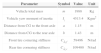
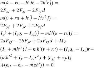
2Vehicle dynamic modelingThe Lagrangian method was used to extract the vehicle lateral motion equations. The proposed model is a 4DOF model including roll angle, longitudinal speed, lateral speed, roll rate. According to Fig. 1, Eq. (1) was obtained as follows [8–10]:

The vehicle's 4DOF model [11].
The longitudinal forces of front and rear tires are ignored due to the negligible variation of them during the maneuvers. The vertical forces on the front and rear axle are assumed to be equal because of the system asymmetry and no longitudinal acceleration and therefore, the effect of their variations on the lateral force is not taken into account. The transverse forces of front and rear axle's tires have important effect on the lateral behavior of the vehicle. The transverse and longitudinal forces on the left and right hand side tires are assumed to be equal. The values of resultant damper and stiffness coefficients of suspension system are considered for the rear and front axles. The applied steering angle will be on the steered tires head. The angle of both tires is assumed to be equal.
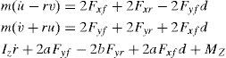
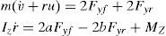
After simplification and elimination of longitudinal speed, a 2DOF model is obtained (Eq. (3)) [9–11].
In Eqs. (1), (2) and (3), the lateral force is obtained through well-known nonlinear Magic formula model, from Pacejka [11].
Fy=Dsin[C arctan{Ba−E(Ba−arctan(Ba))}] where:
where, B, D, C, E are stiffness, peak and shape coefficients, respectively and c1, c2 are the maximum lateral stiffness and load at maximum lateral stiffness, respectively. In Eq. (4), ¿ is the slip angle of tire and is separately calculated for each axle.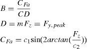
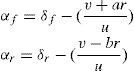
In the case that the rear axle is steering, the steering input term is not equal to zero for the rear axle, otherwise it is equal to zero. Eq. (6) expresses a liner relationship between lateral force and slip angle [11].

Fig. 2 depicts the calculated force from Eqs. (4) and (6) for both axles of the tested vehicle.

By substituting Eqs. (5) and (6) into Eq. (3), the two degrees of freedom model is obtained as following,
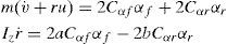
It can be rewritten in state space form as:
3Design of optimal controller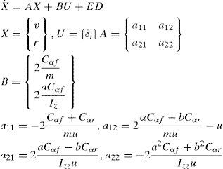
As discussed earlier, improved steering and desired stability are two important aspects of optimal steering of vehicle. The 2DOF model is taken into account and since the objective is to achieve the desired value for variation of roll angle therefore the tracking control method was selected. So, the Performance Index for the optimal steering of vehicle is defines as [12],
where, R and Q are weight matrices. The minimization of Performance Index was performed in order to optimize steering behavior of vehicle. By desired choosing of weight factors (Eq. (6)) and proper design of control law, the favorable value of roll angle variations and optimal steering were obtained and the dynamical constraints of vehicle were met. The Hamilton's function was obtained from Eq. (9).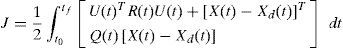
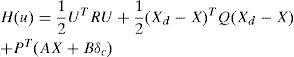
The state equations are written and according to the constraints and boundary conditions, the algebraic nonlinear system of equations is obtained. The time related to the transient part of the system answer is very short, thus this system is studied in stable conditions. Eq. (11) presents the result.
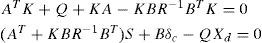
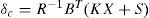
The above system of equations is analytically solved and the optimal control law is attained.
The desired steering during turning and standard maneuvers (like Lane change) is not achieved with zero roll angle, but in order to design of controller for 2DOF model assuming that vehicle is moving with constant longitudinal speed during a turn with constant radius of R, the desired value of ¿¿ is defined as [13],
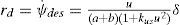
In fact, the desired value of system state is determined through Eq. (14).
3.1Estimator
Since some of the system states cannot be measured and they are effective in determination of controller output, these variables should be extracted. Hence there is a need to an estimator in a control system. In this paper, the lateral and longitudinal speed states which are required for determination of inputs to the optimal controller are extracted by simple estimation method. In order to estimate u and v by using longitudinal acceleration sensors, the acceleration of roll rate is obtained through following estimator [14–15]:
where, axm, aym and rm are measured values of longitudinal acceleration, lateral acceleration and roll rate, respectively. u¿ and v¿ are the estimated values of longitudinal and lateral speed.3.2Modeling by HIL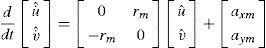
Due to the lack of experimental facilities for testing of a real vehicle equipped with the considered controller, the HIL method is used for the modeling as shown in Fig. 3. In this paper, an ECU is designed and manufactured using Atmega16 microcontroller from AVR family. It is connected to a computer through serial port. The vehicle model is simulated in the computer and the output values of the system are transmitted to the ECU through the serial port as model sensors outputs. The ECU circuit acting as controller, by receiving information from the system creates the modified steering angle by using linear optimal control method and estimation of lateral speed. This modified steering angle is returned to the simulated system as an input and forms a closed control loop. The Simulink MATLAB is used for the simulation and CodeVision is used for the coding of microprocessor.
4Results and discussion4.1Model validation
The Jeep Cherokee vehicle was selected for the modeling. Table 1 shows the related parameters for this vehicle. The results accessed from Ref. [16] were related to a J-Turn test. The test conditions were as following: the steering input was J-Turn type and the maximum steering angle was 310 degree applied to the simulation model. The vehicle's longitudinal speed at the onset of test was equal to 73.86Km/h. Fig. 4 shows the steering angle in both simulation and real test conditions.
Vehicle parameters [1].
| Parameter | Symbol | Value | Unit |
|---|---|---|---|
| Vehicle total mass | m | 1988 | Kg |
| Vehicle yaw moment of inertia | Iz | 4513.4 | Kgm2 |
| Distance from CG to the front axle | a | 1.15 | m |
| Distance from CG to the rear axle | b | 1.43 | m |
| Front tire cornering stiffness | C¿f | 59496 | N/rad |
| Rear tire cornering stiffness | C¿r | 109400 | N/rad |
 J-Turn test, b) simulation.")
Actually, the input of this test was extracted according to the United States National Highway Traffic Safety Administration's (NHTSA) Vehicle Research and Test Center (VRTC). The steering input was applied with 0.5sec delay in the real test, thus the real model outputs have time delay as same as this value. The results obtained show that the nonlinear 4DOFmodel gives the same lateral acceleration as the measured one (Fig. 5).
![a) lateral acceleration of the real test [14]; b) simulated lateral acceleration.](https://static.elsevier.es/multimedia/16656423/0000001200000004/v2_201501220327/S1665642314700938/v2_201501220327/en/main.assets/gr5a.jpeg?xkr=ue/ImdikoIMrsJoerZ+w997EogCnBdOOD93cPFbanNcX6PcOHo8VDqRKrp6xHZ/NlPxKUvo805ICrHlplwxcm7hYIESfjCCTNDlVokL+8rOOaPxhZiq+4NPMXNmvo4s8a5welPBfgnaL6cp6n0zbmgcDhiTFyGKjnUv7vyX3+uQoc8abV2BDOm8g/qqN4NP9EiiOIwXXqCavBUTu9u4Ugq69bwgZ++00QKcUayAyjIlCIsfjiNNPqiMdHLig7wwvwA+L/9nYcHEVU0RKSnQ3Or6qSDwUAPPCTeHBXbth0lHxbox5iLLxkf9joS96bWcd7tUxJWkn2/7163ecnCQH9g== "a) lateral acceleration of the real test [14]; b) simulated lateral acceleration.")
![a) lateral acceleration of the real test [14]; b) simulated lateral acceleration.](https://static.elsevier.es/multimedia/16656423/0000001200000004/v2_201501220327/S1665642314700938/v2_201501220327/en/main.assets/gr5b.jpeg?xkr=ue/ImdikoIMrsJoerZ+w997EogCnBdOOD93cPFbanNcX6PcOHo8VDqRKrp6xHZ/NlPxKUvo805ICrHlplwxcm7hYIESfjCCTNDlVokL+8rOOaPxhZiq+4NPMXNmvo4s8a5welPBfgnaL6cp6n0zbmgcDhiTFyGKjnUv7vyX3+uQoc8abV2BDOm8g/qqN4NP9EiiOIwXXqCavBUTu9u4Ugq69bwgZ++00QKcUayAyjIlCIsfjiNNPqiMdHLig7wwvwA+L/9nYcHEVU0RKSnQ3Or6qSDwUAPPCTeHBXbth0lHxbox5iLLxkf9joS96bWcd7tUxJWkn2/7163ecnCQH9g== "a) lateral acceleration of the real test [14]; b) simulated lateral acceleration.")
a) lateral acceleration of the real test [14]; b) simulated lateral acceleration.
Fig. 6 illustrates that the roll angle has reached to the maximum of 6 degree in the real test which is compatible with simulation results. After validating the nonlinear model, the compatibility of two-degrees of freedom model to the more complete model should be evaluated. The standard sinusoidal test was used for simulation and designing of the controller. The test speed was 80Km/h or 22.2m/s. The steering amplitude of tires was 3 degrees and the variation frequencies were 0.5Hz.
4.2Controller design real test; b) simulation.")
Firstly the weight coefficients for the optimal design of controller should be selected and then the ratios of Q22 to R and Q22 to Q11 were selected and evaluated. The simulation results indicated that the best choice for final controller design was achieved from Eq. (16).
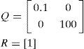
Then, since the longitudinal speed exists within the coefficients matrix, it should be evaluated that how the three control coefficients (K1, K2, S2) vary with the longitudinal speed. Fig. 7 shows the variation of coefficients versus longitudinal speed. As can be seen in Figs. 7, 8 and 9 the variations of control coefficients versus longitudinal speed can be ignored or it can be approximated by a third order equation using curve fitting methods. In this paper, just the variation of K1 is taken into account and the effects of the other two parameters are disregarded.
 The variation of S2 versus longitudinal speed; b) The variation of K1 versus longitudinal speed; c) The variation of K2 versus longitudinal speed.")
 The variation of S2 versus longitudinal speed; b) The variation of K1 versus longitudinal speed; c) The variation of K2 versus longitudinal speed.")
The results show that the optimal controller with estimator can effectively make the vehicle stable in snowy road conditions and prevents it from any accident. Then, the controller was exited from simulation mode and the output values of hardware controller were inputted to the system instead of it. This hardware controller gets the same simulated controller inputs through RS232 cable and after processing, returns it to the simulated dynamical system. The hardware in the loop simulation indicates that the considered hardware can immediately calculate the control method and apply it to the vehicle.
5ConclusionsIn this paper a new nonlinear 4DOF model was proposed to optimal control of SBW system by using hardware in the loop method. A nonlinear 4DOF model was developed; then it was simplified to a 2DOF model with reasonable assumptions to design observer and optimal controllers. The obtained results indicated that the utilization of hardware in the loop method for controlling of a SBW system can favorably stable the vehicle in critical conditions and sudden maneuvers on the roads with low friction. In addition, simulations demonstrated that the proposed controller can considerably improve vehicle handling during a severe maneuver.


 comparison of the applied steering by the driver and HIL controller; b) comparison of the roll rate and HIL controller; c) lateral acceleration in HIL controller; d) lateral speed in HlL controller; e) The vehicle path with and without hardware controller.")
 comparison of the applied steering by the driver and HIL controller; b) comparison of the roll rate and HIL controller; c) lateral acceleration in HIL controller; d) lateral speed in HlL controller; e) The vehicle path with and without hardware controller.")