


The Static VAR Compensator (SVC) and Static Synchronous Compensator (STATCOM) have the ability to provide dynamic compensation to a transmission system. Their speed of response enable increased transient stability margins, voltage support enhancement, and damping of low frequency oscillations. The main operational objective of both FACTS devices is to increase power transmission capability by voltage control at the point of connection of the power network. In this research both controllers are compared by their most important features, such as the following: the performance VI and VQ curves, the response time, the physical size, the cost and behavior in steady-state and transient stability. Results show a small advantage of the STATCOM.
Voltage magnitude throughout the network cannot deviate significantly from its nominal value if an efficient and reliable operation of the power system is to be achieved. Voltage magnitude regulation in the network is achieved by controlling the production, absorption and flow of reactive power throughout the system. Reactive power flow is minimized so as to reduce losses in the network, and voltage regulation is generally carried out locally. Traditionally the following devices are used for this purpose: automatic voltage regulators (AVR) controlling a generator's field excitation so as to maintain a specified voltage magnitude at generator terminals, as well as sources or sinks of reactive power, such as shunt capacitors (SCs), shunt reactors (SRs), rotating synchronous condensers (RSCs) and SVC. SCs and SRs are either permanently connected to the power system or can be switched on and off according to operative conditions. Nevertheless, they provide passive compensation since their production or absorption of reactive power depends on their rating and the bus voltage level at which they are connected. On the other hand, the reactive power absorbed/supplied by RSCs and SVCs is automatically adjusted so as to maintain fixed voltage magnitude at connection points. Load-tap changing transformers (LTCs) whose main function is to regulate voltage magnitude at its terminals by changing their transformation ratio.
Advances in power electronic technologies together with sophisticated electronic control methods made possible the development of fast static compensators namely Flexible AC Transmission Systems (FACTS).
The FACTS technology has become one of the most valuable compensation techniques, because it applies the latest advances in power electronics to achieve additional and more effective control of the parameters of the electrical systems. This represents the most efficient combination of conventional primary equipment, high power semiconductor devices, microelectronics and telecommunications equipment, allowing a most flexible power electric system.
This paper reports on the comparison of two FACTS controllers in parallel or shunt connection, the thyristor-based SVC and the STATCOM. The SVC has made the rotating synchronous compensator redundant, except where an increase in the short-circuit level is required along with fast-acting reactive power support. The STATCOM is the most recent static compensator based on the use of voltage source converters (VSCs) and provides all the functions that the SVC can provide, but at a higher speed (Angeles-Camacho, 2005).
On the other hand, research focuses on the impact of compensation of the SVC and STATCOM controllers, especially on the steady-state analysis (Kamarposhti & Lesani, 2010; Moazzami, Hooshmand, Khodabakhshian, & Yazdanpanah, 2013) and for first-swing stability enhancement (Tan, 1999). The application of the shunt-connected FACTS including placement, sizing, PV curves, voltage profile, power losses and loading margin are also investigated in Sode-Yome, Mithulananthan, and Lee (2007). There has been a significant body of literature, as previously mentioned in the technical analysis of shunt-connected FACTS; in some papers both the SVC and the STATCOM have presented similar benefits, while in others the connection of STATCOM is slightly better. In terms of economic/business feasibility for transmission enhancement, however, the STATCOM has disadvantages (Ramanathan, Elizondo, Enslin, & Zhang, 2006). Similarly, the impact of the SVC and STATCOM on the performance of distance protection is unfavorable (Albasri, Sidhu, & Varma, 2007). According to these, studying and comparing these controllers holistically would be useful. The objective of this paper is to present an integral comparison of the major aspects above. Applications of FACTS devices have continued to increase; accordingly, the results of this paper can be a reference to support engineers who are responsible for implementing these devices.
The remainder of this paper is organized as follows. Section 2 gives a description of the SVC and STATCOM and their schematic representations. Models and the general characteristics from both controllers are also described. Section 3 discusses the comparison between SVC and STATCOM through the voltage–current (VI) and the voltage–reactive power (VQ) performance curves, time of response and installation size. Finally, in Section 4 simulations of the steady state and transient stability are presented and analyzed.
2The shunt-connected FACTS controllers2.1Static VAR CompensatorThe SVC consists of a group of shunt-connected capacitor and reactor banks with fast control action by means of thyristor switching. A SVC can be considered as a variable shunt reactance, which is adjusted in response to power system operative conditions in order to control specific parameters of the network.
Depending on the equivalent SVC's reactance, i.e., capacitive or inductive, the SVC is capable of drawing capacitive or inductive current from the electric power system at the coupling point. Suitable control of this equivalent reactance allows the regulation of the voltage magnitude at the power system node where the SVC is connected. SVCs achieve their main operating point at the expense of generating harmonic currents, and filters are normally employed with these kinds of devices.
A SVC may include a combination of both mechanically and thyristor-controlled shunt capacitors and reactors; however, the most popular configurations for continuously controlled SVCs are the combination of either fixed capacitor-thyristor controlled reactor (FC-TCR) or thyristor switched capacitor-thyristor controlled reactor (TSC-TCR) (Fuerte-Esquivel, 1997). From the point of view of steady-state modeling and simulation, however, both devices can be treated similarly. Additionally, a SVC is connected to the system via a direct connection or by a coupling transformer. The function of a transformer has two main goals: (i) to connect the SVC at high voltage responding to an economic criterion and (ii) to filter the current of third harmonic that occurs as a result of the firing angle of the thyristors and by the presence of resonances in capacitor banks. The FC-TCR structure is shown in Fig. 1a and is used to derive the SVC power flow model in Fig. 1b.
 FC-TCR structure and (b) power flow model.")
This device has become relevant because of the following: (i) it does not require major maintenance, since it has no rotating parts, (ii) fast response times of the order of milliseconds, (iii) voltage control can be independent of phase, (iv) minimal losses associated with its operation, (v) high profitability in comparison with the installation of new transmission lines and (vi) can help with reactive power during failures. The SVC also has some disadvantages, however; the most outstanding is the generation of harmonics.
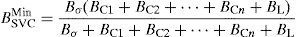
In steady-state model, the SVC current in function of the system voltage Vk and the susceptance BSVC is determined as
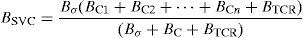
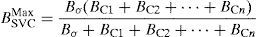
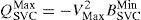
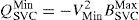
For the configuration with the down transformer, the susceptance is determined bywhere Bσ corresponds to the susceptance of the transformer, BTCR varies from 0 to BL, with firing angles of 180° to 90°, BL represents the susceptance of the reactor and BC is the susceptance of capacitor bank. Thus, expressions for the maximum and minimum susceptance are determined as follows:The thresholds of reactive power that can be exchanged to the system are defined as2.2The Static synchronous compensator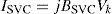
The static synchronous compensator (STATCOM or SSC) consists of one DC/AC high power converter that is based on solid-state elements, high power switches and other auxiliary devices. These elements are capable of generating and/or absorbing a variable reactive power in order to maintain control of specific parameters of the bus. Based on their principle of operation, the converters can be grouped as a VSC (typically a capacitor) or a current-sourced converter (usually an inductor), with a DC signal input. The STATCOM actions are performed without the need to implement large banks for energy storage, such as the SVC systems, and its operation is not impaired by the presence of low voltages (Hingorani & Gyugyi, 1999).
The STATCOM according to IEEE is a synchronously static generator that is operated as a static compensator of VARs in parallel connection, with an output current, either capacitive or inductive, that can be controlled independently of the voltage of the system (Mathur & Varma, 2002; Song & Johns, 1999). Generally, we can consider the STATCOM as a device formed by a transformer associated with a VSC that has as input a DC voltage signal and a three-phase voltage as output. Each voltage is on phase and coupled to the corresponding AC system; moreover, the transformer reactance has a small value because of the reactors and the magnetic coupling. These output parameters can be varied to control specific variables of the power system at the point of connection. The DC voltage necessary for the operation of STATCOM is provided by a capacitor capable of storing the energy required. The schematic representation of the STATCOM and its equivalent circuit are shown in Fig. 2.
 schematic representation and (b) equivalent circuit.")
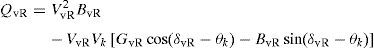
The shunt voltage source of the three-phase STATCOM may be represented by EvR. The reactive power flow is determined mainly by the magnitude of the voltage bus, Vk, and the VSC output fundamental voltage, VvR. The model of STATCOM can be derived from its principle operation, and given by a source coupled in parallel to the node through a impedance in series (YvR=GvR+jBvR), expressing the current supplied to the connected bus as
In addition, the reactive power is expressed aswhere δvR and θk are the voltage phase angles. For VvR>Vk, the controller generates reactive power and consumes reactive power when VvR<Vk.3Comparison between the STATCOM and the SVC
Until now, the SVC and the STATCOM are the FACTS most connected to power systems; however, while sharing the same operating principle, they present a significant technology gap. By the inspection of (1)–(7) and Figs. 1 and 2, clearly the basic characteristic at the connection point of the SVC is equivalent to a voltage-controlled shunt susceptance, whereas the STATCOM behaves more like a voltage source behind a reactance. This accounts for the STATCOM's generally superior functions, better performance and greater applications. These characteristics are summarized and shown below.
3.1VI and VQ curvesConsidering the curves which relate voltage magnitude to current (VI) or reactive power (VQ) for the aim of voltage support capabilities is common. A decrement in system load level results in an increase in voltage magnitude at all system nodes. Both the SVC and the STATCOM holds the voltage magnitude by absorbing inductive current. On the other hand, an increase in the system load level produces a decrease in nodal voltage magnitudes. For this condition, the devices maintain the voltage magnitude by injecting a capacitive current. In Fig. 3, there are the VI and VQ curves for the SVC and the STATCOM.
 VI and (b) VQ curves for SVC and STATCOM.")
With reference to Fig. 3a we see that STATCOM's ability to provide current compensation is more extensive than the SVC's; even at low voltages levels the STATCOM can continue to supply the full rated reactive current to the system, i.e., the output current is independent of the system voltage, whereas the compensating current of the SVC decreases linearly with the system voltage. This can also be observed in Eqs. (1) and (7).
A similar approach is taken for reactive power compensation; in this case, Fig. 3b and Eq. (8) show that the maximum VAR generation or absorption of the STATCOM changes linearly with the system voltage, whereas in Eq. (5) the SVC the VAR output decreases as the square of this system voltage (CIGRE, 2000). Additionally, the SVC cannot transiently increase the generation of VAR since the high capacitive current consumed is determined strictly by the size of the capacitor bank and the system voltage magnitude.
Moreover, in the SVC if the system voltage is lower than the reference voltage, the impedance offered by the reactor is high. Additionally, if the system voltage is increased to exceed the reference voltage, then the mechanism of SVC switches the reactors to decrease the impedance of the inductive branch. The impedance of the capacitive branch varies linearly with applied voltage according to the characteristic of the capacitor admittance. Note that if the SVC has an upper voltage, it behaves as an inductive element (absorbing reactives), and for any lower voltage the SVC is a capacitive element (adding reactives).
3.2Physical size and installationThe function of the STATCOM is also to exchange reactive power capacitive and inductive, and the large capacitor bank including its protection and switching equipment is not required, which has been used in the conventional SVC. STATCOM reduces by 30–40% of the overall size as well as installation costs. The scheme of comparison is illustrated in Fig. 4.

Thus, STATCOM's small physical size is optimal for installations in areas where the floor has a high cost and for applications where the system can require a relocation of the installation.
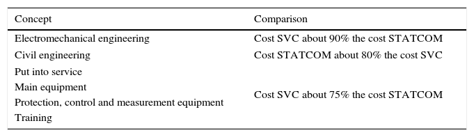
3.3CostFor both FACTS, the costs can vary depending on voltage, land requirements, construction time, operation and maintenance, repair, workers, substation equipment, access, roads, service, permits, licenses and financing. For the STATCOM, the specific costs depend on the transformer, the DC source, the semiconductors and the respective snubber to protect them. While for SVC cost depends on passive elements such as inductors and capacitors composing TCR and TSC. Grouping these concepts, Table 1 shows a comparison between the costs of both.
Cost comparison between SVC and STATCOM.
| Concept | Comparison |
|---|---|
| Electromechanical engineering | Cost SVC about 90% the cost STATCOM |
| Civil engineering | Cost STATCOM about 80% the cost SVC |
| Put into service | Cost SVC about 75% the cost STATCOM |
| Main equipment | |
| Protection, control and measurement equipment | |
| Training | |
In general, the STATCOM is more expensive than the SVC. Nevertheless, the physical size of the installation of an SVC influences civil engineering cost. Thus, the civil engineering cost of a STATCOM is 80% that of a SVC of the same electrical characteristics.
At present, the cost of the STATCOM seems to be competitive with the SVC. The above due to potential applications of STATCOM have demonstrated more robust.
4Simulation resultsA set of simulations are presented in order to analyze and compare the steady-state and transient performance of SVC and STATCOM, highlighting the advantages and benefits provided by each of these compensators in a power system.
The software NEPLAN® has been used to realize the simulations. The behavior of a test network from Stagg and El-Abiad (1984) and Acha, Fuerte-Esquivel, Ambriz-Pérez, and Angeles-Camacho (2004) is taken into account, which consists of five nodes interconnected by seven transmission lines, two generators and four loads connected in four of the nodes, as is shown in Fig. 5. The network operates with a frequency of 60Hz; furthermore, the voltage and power value are 400kV and 100MVA respectively as the system base.
4.1Power flow studies
Power flow is the name given to the steady-state solution of a power electric system under prescribed conditions of generation, load and network configuration in order to find the nodal voltages, power flows, power losses and compensation requirements. In the case of reactive shunt compensation applications, the likely specific objective of the power flow studies are the following: (i) to determine appropriate location; (ii) to provide information about the power flows under normal and compensated conditions; and (iii) to identify required control, settings and limits. In the present work a simple power flow study is performed in order to assess the effectiveness in controlling the voltage magnitude by both controlling the SVC and the STATCOM, i.e., voltage support. The power flow results for the test network are illustrated in Fig. 6. In Fig. 6a the power flow is presented which is taken as the base case without compensation. In Fig. 6b and c the results are shown that have been obtained by placing a SVC and a STATCOM of 200MVAR in Lake, respectively.
 without compensation, (b) with SVC and (c) with STATCOM.")
As expected, both devices can control the voltage magnitude at the specific value. The power flow results indicate that in order to keep the nodal voltage magnitude at 400kV (1p.u.) at the bus where the SVC or the STATCOM is connected, those inject 38.805MVAR and 38.749 of reactive power respectively. In general, an improvement can be seen in the network's voltages profile. Furthermore, the reactive power flow has been increased almost 20 times to the Main node via L6, for the case without compensation. Clearly, the reactive power flow has been incremented between the Lake node and the South node through L3; the large amount of available absorbed reactive power is provided by the synchronous generator GEN2, with a value of 61.043MVAR with a SVC installed and 30.118MVAR for the case of the simple network.
The presence of STATCOM and the SVC improve the voltages in most nodes, compared to the simple network, except in the Elm node, which is far from the compensators.
In steady state, both compensators present similar improvements. In this case, GEN1 significantly reduces the generation of reactive power since it has a value 2.683MVAR compared with 7.551MVAR in the base case. Moreover, reactive power flow between nodes North and Lake, presents an increase of approximately 10MVAR in the line L2, with respect to the case without compensation, which is also absorbed by the machine GEN2. For completeness, it should be mentioned that the power losses decrease from 3.62% to 3.58% when devices are present.
4.2Transient-state analysisTime-domain simulations are generally used to carry out large disturbance studies to determine the response of the power system and to determine the stability and damping of the electromechanical oscillation following any contingency and/or alterations in the operation of the same. For shunt-controlled reactive compensation some applications of large disturbance studies include the following: (i) to determine appropriated locations and ratings; (ii) to provide information on the transient response and damping; (iii) to provide information about the interaction of the reactive source with the power system components; and (iv) to identify enhancement to power transfer limits, transient stability and system damping.
For these studies, power networks are modeled as a set of algebraic and differential equations. Using the results of power flow studies to provide initial conditions, the differential equations are solved by numerical integration. The test network of Section 4.1 is now used for transient stability studies to obtain their operating performance during a disturbance without and with shunt-connected FACTS. A three-phase fault at South node has been applied to the network.
This paper considers SVC and STATCOM models along with their complex control systems. In the case of the SVC, its control indicates the necessary susceptance to provide/absorb reactive power. STATCOM's control determines the current to control the suitable reactive power flow. In both controls, reactive power as voltage at the connection point are important for calculating control variables.
In the following figures, the behavior of the system is presented in the transient-state assuming three different network topologies: without compensation, with SVC and with STATCOM. In these three cases, a failure occurs in the 1.1s with a duration of 0.2s; the simulation time is 10s. In Figs. 7 and 8, the benefits and contributions of the compensators to the system are shown.
 without compensation, (b) with SVC and (c) with STATCOM.")
 without compensation, (b) with SVC and (c) with STATCOM.")
Additionally, in Fig. 7, the magnitude of voltage at the nodes of the network is shown, which remains constant to the value 1.1s before the three-phase fault occurs. The presence of a short circuit involving a voltage drop to zero at the node of the fault, increasing the value of the current that flows in the network. Without compensation, all voltages fall and remain low in the time in which the contingency of 1.1–1.3s lasts. In the figures, we can see that the only bus which reaches zero is the South node, which is where the fault has a major effect. Consequently, the results of the fault are also reflected in the others buses with voltage drops. Once the fault is released, the system attempts to restore its initial conditions, but in this case the fault has been large and the system is disturbed, presenting oscillations and alterations that do not allow its recovery.
In the interval of the fault, 0.2s, the visible drops remains constant in the South node, that is, the voltage falls to a value of zero because of the fault. Despite the presence of the compensator, no change in voltage magnitude is observed, whereas in North, Lake and Main the effect of the installed STATCOM is clear; the compensator injects reactive power to the network, trying to raise the voltage magnitude of the nodes, in comparison with Fig. 7a. In Fig. 7c slopes with large inclination during the presence of the disturbance on the voltage magnitude of the buses can be appreciated. That is, the STATCOM has a high ability to respond, since the voltage is raised to a magnitude of a higher level than the SVC at the same time of operation, including bus Elm, which is far from the compensator. This is an advantage of the operation of STATCOM, which does not occur in the case of the SVC.
As a consequence of the three-phase fault in the network, the machines are also affected in their performance and behavior, which are connected to the North and South nodes. This is expressed in the speeds of the rotor in Fig. 8a. On the other hand, generator connected in the South node shows a sudden increase in its speed because this bus is the place where the failure occurred, whereas generator North drops its speed. After the contingency, the machines did not return to steady state, and the speed of the machine connected to the North node continues to fall, while the speed of the rotor of generator South shows sustained oscillation.
Synchronous machines benefit from the effect of the FACTS controller, which is shown in Fig. 9 when the SVC and STATCOM are installed. The reactive power graphs of the SVC and STATCOM shows that before the fault, the compensator delivers 37,602MVAR and 37,549MVAR respectively to the system. When the disturbance then occurs in the compensator, the injection of reactive power almost immediately stops and the compensators switches to a state, which absorbs MVAR, while machines recover their stability. The STATCOM absorbs reactants of approximately 3s and then starts to inject reactive power once again to recover its initial value, allowing the voltage at the nodes and the generators to return to normal operation. Note that the STATCOM operation is recovered in less time than the SVC.
5Conclusions
This paper focuses on the technical comparison of two of the most currently used FACTS shunt compensators: the SVC and the STATCOM. The advantages and disadvantages between these devices have been presented based on their basic operating characteristics, with the intention of highlighting and comparing the benefits that they can bring to a power system. The basic operation characteristics and the mathematical models have shown that the STATCOM provides better support under faulted conditions, when reactive current is needed. No notable difference is detected in steady state.
The 5-bus system was used in order to illustrate the steady- and dynamic-state performance of both devices in power systems. As expected in the steady state, the magnitude of the voltage remained at the specific value in both cases. In the dynamic analysis when both devices are compared, the system tested is stable for this disturbance only when shunt devices are connected. The STATCOM has a certain advantage over the SVC controller, since the STATCOM acts immediately in the right direction by boosting the voltage during the fault, enabling a lower magnitude in the first-swing and a faster recovery.
The technology of FACTS represents an alternative to control. The design and implementation of a control system more efficient for the governors of the machines and for proper control of SVC and STATCOM controllers to improve their response to contingencies of large magnitude are important topics for further research.
Conflict of interestThe authors have no conflicts of interest to declare.
The authors gratefully acknowledge the support of S. Olvera-Sumano, J. Sosa-Lopez, undergraduate students of the Facultad de Ingeniería, UNAM.
Peer Review under the responsibility of Universidad Nacional Autónoma de México.