


This paper presents an algorithm of simultaneous localization and mapping (SLAM) with a scanning laser range finder and radiofrequency identification technology (RFID) to include landmarks of an object or place within a generated map. For the testing phase was used of simulation software Anykode’s Marilou and was used to build a virtual mobile robot with the features of the Pionner 3-AT, including a Hokuyo URG-04X scanning laser range finder and an Innovations RFID ID-12 reader. Validation of results was carried out with the cycle closure process to obtain the average error of the navigation path, resulting on an error of less than 50mm.
Este artículo presenta un algoritmo de localización y mapeo simultáneos (SLAM) con telémetro láser y un identificador de radiofrecuencia (RFID), con el propósito de incluir la referencia de un objeto o lugar dentro del mapa generado. Para la experimentación se utilizó el software de simulación Anykode Marilou, mediante el cual se construyó un robot móvil virtual con las características del Pionner 3-DX, con un telémetro láser Hokuyo URG-04X y el lector RFID ID-12 de Innovations. La validación de los resultados se realizó con el proceso de cierre de ciclo, con el fin de obtener el error promedio del recorrido de navegación, logrando un error menor a los 50 mm.
For decades, research has focused on attempting to simulate common human actions like walking, running, talking and even thinking. One of the qualities of humans that has gathered the most attention from scientists is their ability to move around in different settings, making researchers focus on navigation techniques that transfer this ability to artificial entities. In 1986, Peter Cheeseman, Jim Crowley and Hugh Durrant-Whyte talked about the topic of simultaneous localization and mapping applying probability (SLAM), during the IEEE Robotics and Automation conference held in San Francisco, United States [1].
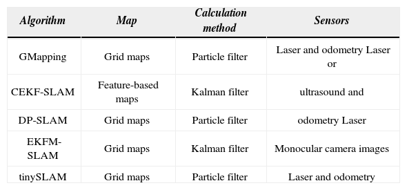
The creation of SLAM resulted in various research that tried to determine which action would be carried out first, localization or mapping [2]-[8]. Multiple algorithms allowing for the simultaneous navigation and localization (SLAM) of mobile robots have been developed since then, both for indoor and outdoor environments. Table 1 includes some of those algorithms.
SLAM Algorithms.
| Algorithm | Map | Calculation method | Sensors |
|---|---|---|---|
| GMapping | Grid maps | Particle filter | Laser and odometry Laser or |
| CEKF-SLAM | Feature-based maps | Kalman filter | ultrasound and |
| DP-SLAM | Grid maps | Particle filter | odometry Laser |
| EKFM-SLAM | Grid maps | Kalman filter | Monocular camera images |
| tinySLAM | Grid maps | Particle filter | Laser and odometry |
The creation of SLAM resulted in various research that tried to determine which action would be carried out first, localization or mapping [2]-[8]. Multiple algorithms allowing for the simultaneous navigation and localization (SLAM) of mobile robots have been developed since then, both for indoor and outdoor environments. Table 1 includes some of those algorithms.
A description of each algorithm included in Table 1 follows. Algorithm GMapping [9] is a particle filter-based online algorithm with Rao-Blackwellization proposing distribution of probabilities that consider the last measure taken by the laser device, and not just odometry. This is done by searching the region closer to the estimated location, defining the probability of each landmark associated to the measure and adding the odometry information; from this, K samples are extracted to estimate a Gaussian distribution matching the mean and variance with the estimated distribution. The particle’s new position is obtained from the resulting distribution. Before resampling, a measure inversely proportional to the variance of particle’s estimations is calculated to assess the need of resampling. This algorithm was tested with data from Intel1, Freiburg2 and MIT3, with good results, generating maps without inconsistencies for each tested data, including analysis from different researchers. One of the setbacks of the algorithm is dynamic objects, as well as objects with complex modeling like grass, wires, etc.
The Kalman filter-based algorithm CEKF-SLAM [10] maps using environment features; it also optimizes algorithm EKF-SLAM by using a compressed filter, which delays updates of covariance, associated to a set of non-local labels. This increases the algorithm’s efficiency without diminishing the accuracy that characterizes full SLAM algorithms. This algorithm was tested outdoors using a car with encoders and a laser telemeter that followed a path during 20 minutes. Results were favorable and demonstrated the optimization of the original algorithm; however, the problem of cycle closure in maps still persists.
The DP-SLAM [11] is a particle filter online algorithm that generates grid maps. Its purpose is to reduce the use of computer resources by avoiding the successive copy of maps per each particle generated at the resampling stage. This algorithm generates a single map, therefore keeping the data structure, and allows knowing at all times the changes made by it and by previous particles. This decreases the computer load by reducing the time it takes to copy data when new particles are created. The algorithm was tested using data sets created with an iRobot ATVR platform and a SICK sensor, in a 60m long, 24m wide environment and a 12m by 40m cycle.
Results were good, but they were not evaluated with existing data sets.
The algorithms previously described use laser sensors and odometry for their explorations, but there is currently algorithm research using stereo and monocular cameras, like algorithm EKFM-SLAM [12], which is totally based on algorithm EKF-SLAM but with a camera added as single sensor. To integrate the camera’s information, the RANSAC (RANdom SAmple Consensus) method was used, which estimates the camera’s motion (Visual Odometry); this method also allows using algorithm EKF with cameras to get estimations of initial parameters, using less landmarks from the camera. Tests were done with a person carrying a camera to simulate the robot and circling the laboratory twice, satisfactorily closing the loop. Research mentions that information processing may be carried out in real time, and testing may be done outdoors, without offering too much information about results.
Lastly, the list on Table 1 also integrates one of the smallest algorithms, tinySLAM [13], implemented with only 200 lines of code in C, and based on a particle filter with a single high resolution occupation grid (1cm). The laser scan updates more than one landmark per line falling on a surface, implementing a function that generates holes in the map to enhance verisimilitude function. With this algorithm, the odometry calculation is used to correlate scans and determine a constant speed for the robot. This algorithm was tested at Paris’s Mines Tech laboratory with a single cycle and the map did not offer favorable results, as it only offered the enhancements obtained only from odometry.
SLAM algorithms may be classified in three: by sensors used, by calculation methods used or by structure. Algorithms classified by sensors include those based on artificial vision [14], range measurement devices (laser or ultrasound) [15] and odometry. Algorithms based on calculation methods may use the Kalman filter or the particle filter; currently, there are hybrid algorithms using both filters, like FastSLAM [16], with its different versions (refer to Table 1). Lastly, algorithms classified by structure are: on the one hand, online SLAM, which stores only the necessary environment landmarks, resulting in fast calculations; however, errors grow exponentially with time. On the other hand, fullSLAM stores each landmark during navigation, causing multiplication of the information with each position prediction.
In the classification based on sensors, different devices are used to implement SLAM, like CCD cameras, which operate in a way similar to the human eye, making them useful to identify objects with artificial vision techniques; however, one of their drawbacks when implementing SLAM is that they obtain extensive features from the environment, turning real time processing and data calculation into slow, complex tasks. This device was, therefore, not used in this research. This work focused on looking for alternatives that would replace a CCD camera, and for environment perception we used a laser telemeter, which collects information through distances within a specified range. This device has the advantage of obtaining only the information that is required to detect the objects in front of the robot; the drawbacks are reflections on clear surfaces and limited angle/range. Therefore, this device is useful for 2D navigations.
CCD cameras are useful to identify objects but, as mentioned before, their use is not viable, so their function was replaced with a RFID (Radio Frequency IDentification) device. This electronic device is used to collect data through radiofrequency waves; it has labels and a transponder (transmitter-receiver) that communicate between them and exchange information to obtain a label’s ID.
This article describes a system based on algorithm tinySLAM, called SLAM-R, integrating the RFID device to the original algorithm. The main idea of this research came from the way humans move in unknown environments, usually taking features from the environment (objects) as landmarks, which later helps to remember locations. In a similar way, the purpose is for robots to not only generate a map and simultaneously locate their position, but also to obtain environment features that allow defining a location within the map, so the robot can move by reminding it the ID (objects) of the RFID label placed on the environment. By using algorithm tinySLAM, a high-resolution map is generated, allowing for faster mapping and less computer resources.
The project scope included the creation of the algorithm only for indoor locations, due to limitations derived from using low-range sensors and the complexity of outdoor environments. In addition, the resulting algorithm is prepared for environments with semi-dynamic objects (occasional movement), as dynamic objects may produce inconsistent maps.
This article is structured as follows: Section 2 describes works related with this research. Section 3 shows the algorithm and diagram used for experimentation. Section 4 shows the design of the robot and navigation circuits to test the algorithm. Section 5 integrates experimentation results and tests. Section 6 details the results. Section 7 exposes conclusions and, finally, section 8 describes the structure of future works.
2Related WorkMatthai Philipose’s research [17] used the RFID technology to improve the position of a mobile robot using a laser telemeter by implementing an algorithm that determines the exact location of the RFID label; however, multiple labels must be placed on the mobile robot’s path for the algorithm to work properly. The research offers no additional information about the environment and only improves the stage of position prediction.
In the article published by Vladimir Kulyukin [18], a landmark-based navigation technique was developed, which is used to help blind people in indoor environments with a robot detecting RFID labels and indication of the person’s location. This research does not use SLAM, but it is one of the few that has implemented RFID.
3AlgorithmUnlike the state-of-the-art algorithms described that have used RFID in navigations systems, SLAM-R generates a 2D map through a particle filter that uses only the laser telemeter information, and adds environment information like position and RFID-object recognition. The navigation system developed consists in 4 stages:
- •
.Stage of prediction and resampling used to determine the robot’s position through the verisimilitude function.
- •
Map update function through Simple DirectMedia Layer (SDL).
- •
The RFID label searching system, which infers over the map creation function and prediction, only in case this exists.
- •
Control system created with commands to determine the robot’s direction.
The navigation system was built using tinySLAM, and a RFID reader was added to the robot, resulting in a diagram as the one depicted in Figure 1.

To estimate the robot’s current position within a semi-dynamic environment, odometry, laser readings and RFID labels are used as additional information to recognize objects within the map through a single identifier (ID). Figure 1 depicts the dynamic Bayesian network model used to represent connections between the environment’s map (M), the laser data (Z), the use of RFID labels as landmarks (R), the robot’s position (S) and odometry (U), all of these arranged in a determined time (t). To estimate the robot’s position, the stage of prediction must be implemented through the following equation (1):

Equation (2) is used at the stage of weights updates and resampling:
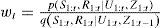
A priori labeling of each object or place passed by is necessary for the navigation algorithm to recognize them; however, the SLAM functioning with not be affected by the lack of labels, as they work independently
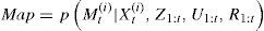
Equation (3) is used at the stage of the map generation.
4Tests and ExperimentationTo test the navigation system, a search for a system that could simulate a virtual mobile robot was carried out. Several simulators were obtained from this search, amongst them Webots [19], Eyesim [20], Mobs [21], Marilou [22]. Based on the devices integrated in simulation and the modeling’s versatility, Anykode’s Marilou simulation software was chosen because, among its advantages, it offers licenses to students, allowing for testing the system for a determined time; it also offers a wide array of virtual devices with the manufacturer’s properties to create a more realistic simulation. This simulator was used for testing by creating both a virtual model of the environment and of the mobile robot to be used. This software allows simulating the behavior of sensors and actuators with a high level of realism; it also allows modeling environments and includes a package of libraries (MODA, Marilou Open Devices Access) to program robots in different languages.
To test the algorithm, a 3D model of the Pioneer 3-AT robot, manufactured by ActivMedia, was created, using the actuators, kinematics and sensors of the real-life model, with limit speeds of 2m/s; a Hokuyo URG-04X laser sensor with a 240 degree radius and up to 4.0m range was added to the model. Figure 2 depicts the Pioneer 3-AT mobile robot virtual model.

Different environments were created to experiment with the virtual mobile robot, randomly placing objects with different textures and adding factors like wind speed and gravity exerted on the robot, controlled by its weight. Figure 3 depicts one of the environments developed to verify the values of sensors and the bearing mechanism by testing, for the first time, the SLAM-R navigation system.

One of the limitations of simulating the navigation algorithm is that the simulation software does not have readers, much less the ability to label objects through RFID; the option was to enable obstacle detection by plugging an ID-12 RFID reader, manufactured by Innovations, to the computer’s serial port, therefore adding a physical device to the simulation through the virtual serial ports of Marilou. Figure 4 depicts the circuit and labels used for the RFID system.

The general process of simulation includes a C++ and MODA programmed system to obtain data from the odometry, laser telemeter and RFID devices; the navigation system also included a class responsible for map construction using SDL libraries. Figure 5 depicts the general process of the simulation system.

Data storage was included in the navigation system using plain text files to save the odometry information, the laser telemeter readings and the labels found on the robot’s path, which would be used later to produce the map from a file. The purpose of this stage is to provide a dataset that can be used as a study tool by the scientific community, reproducing the simulations created in this research.
5ResultsEvaluation of results was carried out by generating a virtual map, which was then compared with the SLAM-R-generated map (both were similar); the robot’s position was monitored to make it match as much as possible with the position offered by the simulation using a cycle closure algorithm, which determines the deviation error accumulated during the circuit’s path. Tests were carried out using 3 different environments and different types of objects, both labeled and unlabeled; the system was also tested without labeling objects to confirm that labels were not indispensable.
Figure 6a shows a simple, obstacle-free scenario to test SLAM, while Figure 6b shows the SLAM results using odometry and laser data only. This environment serves as a basis to analyze behavior in future environments.

Figure 7a shows the simulated environment with objects of different sizes and shapes, keeping the squared structure of the environment from Figure 6a, in order to highlight the difference in behavior of the SLAM when adding RFID labels. For this particular environment, numbers 1 to 8 were used to identify objects. Figure 7b includes the map showing only 7 of the 8 objects labeled; this was, however, done on purpose because the corresponding label was not placed at the reader’s range when the robot approached the object; in this system, it is possible to exclude certain objects and label only those that are of interest to researchers. Labels were placed on the map as the reader detected the labels, and these were placed immediately on the generated map; therefore, labels have different positions.

Figure 8a’s third environment shows a semi-rectangular map with realistic objects, like boxes and plant pots, to assign real names to objects and test for correct labeling. Figure 8b shows each labeled object. As a result, the label’s position was improved; it was placed at the center of the object by calculating the distance provided by the laser and the average range of the RFID reader. Figure 8c only shows a zoom image of the name assigned to a SLAM-R-build map object.

To evaluate results, the cycle closure technique was used, which consists on moving on the path with the SLAM-R system and storing data files collected during navigation (odometry, laser and RFID labels), with the purpose of moving on that same path again but in the opposite direction, that is, readings are collected from the last to the first one, and the same navigation algorithm is used. During the process, the SLAM-R algorithm positions are stored in a plain-text file, so that the degree of error obtained during the circuit’s path can be later analyzed. To analyze results, the robot’s positions during the path are graphed, both for its forward and backward motions, and the degree of error between the initial and final points of the path is calculated in millimeters, in order to define how far they are from each other.
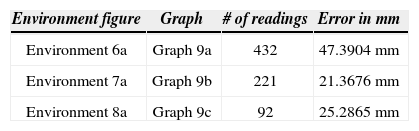
Figure 9 depicts the robot’s paths for each virtual map used for tests; Figure 9a corresponds to Figure 6a’s environment; Figure 9b corresponds to Figure 7a’s environment and, finally, Figure 9c corresponds to Figure 8a’s environment. These graphs represent forward motion with a solid line and the backward motion with a dotted line; the error between both paths can be seen between both lines. Table 2 shows error results in millimeters for each environment.

The results obtained by simulation prove that the developed algorithm is suitable to generate 2D maps in small indoor environments, and that RFID labels help to improve the robot’s final position because they are landmarks with more relevance to calculate the algorithm; this is demonstrated with an error of less than 50 mm. It was also determined that the SLAM-R navigation algorithm identifies labels with 100% accuracy during simulation, because measurement conditions are ideal – there are no factors preventing the reader from reaching the manufacturer’s specified range. Therefore, it is important to test the algorithm on a real robot, confirming that simulation-obtained results are the same as real life results. A simulated system, however, always has constant variables and conditions are ideal for tests, whereas real-life tests may face factors that change results. A relevant example for this would be the RFID measurement distance; this device was simulated in a physical form and, at times, the reader could not detect the label, which may be caused by environmental interferences or noise.
One of the limitations of the proposed algorithm is the dependence on RFID labels, placed on the environment for object identification; however, this does not hinder the algorithm from continuing with the navigation because, if an object is unlabeled, it will be represented as an object without its particular features, indicating the robot that it cannot go through that place.
In future works, an environment resembling the features of the Electronics Laboratory of the Institute will be created to test the SLAM-R algorithm on a physical robot, using the same devices of the simulation herein described. The purpose of these works would be to evaluate results from both cases and establish the causes and factors influencing real-life environments not included in simulations for this type of navigation systems.
Intel (American multinational semiconductor chip maker corporation): http://kaspar.informatik.unifreiburg.de/~slamEvaluation/datasets/intel.clf