


This paper describes the simulation of movement control of a one-degree-of-freedom articulated robot arm SCARA actuated by a pair of McKibben pneumatic artificial muscles. The pneumatic artificial muscle is the actuator and emulates the behavior of biological muscles; due to its nonlinear behavior, there is also a need to develop control systems for robot arms using this type of actuator. Research begins with the transfer function that represents, in mathematical language, the movement of the robot arm’s joints; this allows using a PID controller on the transfer function and generating data to train the Multilayer Perceptron Artificial Neural Network (RNAPM). So far, the PID control system has been able to control the movement of robot arms but, based on experimental tests, the RNAPM has proved to outperform the PID control’s response time by up to 2.95 seconds, minimizing the angular error by 1.3° and avoiding the oscillation problem due to its continuous, constant behavior.
The evolution of robot arms actuated by pneumatic artificial muscles has its origin in the 1950s with physicist Joseph L. McKibben [1], who designed and developed the first prototype of an artificial muscle for the pneumatic control of an orthosis that would expand and contract like an actual human arm; this artificial device is a close emulation of biological muscles [2].
The pneumatic artificial muscle is amongst several types of actuators that have been used in robotic arms; others are the hydraulic, electronic and pneumatic (pneumatic cylinder) actuators. However, the pneumatic artificial muscle has advantages with respect to more classic actuators: great initial force, high acceleration capacity, steady movement; it is both lightweight and sturdy, it may be positioned in different angles without losing properties, which makes it appropriate for hazardous environments [3], and it can be actuated directly or controlled with open loop, as hysteresis in the theoretical-mathematical behavior is close to the behavior observed during experimental physical tests [1].
Strictly, the control of a pneumatic artificial muscle-actuated robot arm, composed by several connected joints, has highly nonlinear dynamics with strong couplings between joints [4]. The robot arm developed by Tondu et al. [5] at the Robotics Laboratory of the National Institute of Applied Sciences (INSA) in Toulouse, France, is one of the McKibben pneumatic artificial muscles that behaves the most like human arms.
Tondu states that one of the drawbacks of this actuator is the nonlinearity of the artificial muscle due to hysteresis, the reason being the effect of friction between fibers inside the woven shell [2].
Caballero et al. [3] consider that the nonlinearity of the pneumatic artificial muscle results from the actuators’ mathematical models not considering that the section of the inner tube is not a cylinder at the muscles’ ends; they agree with Tondu in that the woven shell-inherent distortions result in a nonlinear contraction repetitiveness.
Pneumatic artificial muscle-actuated robot arms have been developed, like the one by Situm et al. [6], who built the arm segment using a Festo Pneumatics antagonist pair of muscles, or that of Choi et al. [7], a robot arm driven by two pairs of pneumatic artificial muscles. The purpose of both designs is to diminish the risks to humans in hazardous industrial environments; both scientific teams agree that the main problem of incorporating pneumatic artificial muscle actuators is the difficulty to develop control systems due to their nonlinearity.
This points to one of the biggest obstacles of control systems: the nonlinear behavior of pneumatic artificial muscles. PID control techniques have been proposed to solve the nonlinearity issue [5] with acceptable results and, therefore, learning-oriented alternatives are also being considered, like Artificial Neural Networks, which have the main advantage of incorporating nonlinear effects during the training stages [8], allowing for the construction of network topologies that resemble this behavior to develop an intelligent control system that improves response times and PID control stabilization.
This paper describes the control simulation of a one-degree-of-freedom, RNAPM-actuated SCARA (Selective Compliance Assembly Robot Arm) robot using PID control-obtained data. This PID controller has been used to control a seven-degree-of-freedom robot arm built at the National institute of Applied Sciences in Toulouse, France [5]. Using the RNAPM, response times were improved by 2.95 seconds and angular errors were optimized by 1.3 degrees.
This paper is structured as follows: Section 2 describes the physical structure of the pneumatic artificial muscle and the transfer function used in control simulation; Section 3 offers a visualization of the simulation methodology constituted by these processes: 1) data collection, 2) RNAPM control, 3) training, 4) nonlinear approximation. Section 4 offers simulation tests and results and Section 5 focuses on conclusions and future projects.
2Pneumatic artificial muscleNowadays, the McKibben pneumatic artificial muscle has become one of the most used actuators amongst researchers to build robot arms due to lower costs, construction easiness and advantages over classic actuators.
Researchers like Tondu [1], Caballero [3], Situm [6], Choi [7] and Selim [9], Lezama [10] and Díaz [11] are amongst those that have used this type of actuator, which consists of an inner rubber tube filled with pressurized air, covered with fibers woven to form a mesh. One of the ends has a rigid, closed connector, where the muscle exerts an outward force, and the other end has a connector that allows the entrance of pressurized air; this way, the inner rubber tube contracts or extends, very much like biological muscles [3].
Díaz [11] and Tondu [2] agree that the artificial muscle’s behavior closely emulates that of human muscles. Figure 1 depicts the structure of a pneumatic artificial muscle actuator.

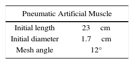
The pneumatic artificial muscle used to simulate the RNAPM control is the one proposed by Lezama [10], who describes the physical features shown on Table 1.
In control theory, transfer functions are used to represent the input-output relation of components or systems that are described through differential equations [12]; that is, transfer functions are mathematical representations of real life behaviors, like the manipulation of a robot arm’s movements.
System control means applying or exerting forces for it to work according to specific instructions, that is, the force determines terms like movement, velocity and acceleration [13]; therefore, the simulation of a robotic arm requires knowing the transfer function and a control system acting on it.
Tondu et al [2] propose the transfer function of a joint composed by an antagonist pair of pneumatic artificial muscles to represent the behavior of elbow movements, as depicted in Figure 2, with angle instructions responding at a range between 0° to up to 55° and the following mathematical representation:
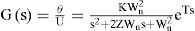

Where U represents pressure (bars), is the position (degrees), K is the static gain, Wn represents the undamped angular frequency, Z is the damping coefficient and variable T represents time.
Based on experimental tests, Lezama [10] also proposes specific values for variables Wn, Z and T mentioned previously in equation (1); the transfer function is then represented as follows:
3Solution methodology3.1Data collection
As mentioned earlier, control simulation necessarily requires knowing the transfer function used by the system control. This paper uses the transfer function described in equation (2), programmed with the Matlab Simulink simulation tool and the PID controller, resulting in a closed loop control system that provides input and output data to train the RNAPM. Figure 3 shows the PID control system diagram.

Lezama [10] also proposes the PID controller values used in the control system diagram of Figure 3, like P=0.06, I=0.12 and D=0.0075; the Required Position variable provides the angular position between 0° and 55° that will define the elbow’s range of movement.
Finally, data is collected by measuring the vector of the Input variable storing all correction values of the angular error and the vector of the Output variable, which is in charge of storing the angular position values proposed by the PID controller to reach the user-specified position at a compilation time of 6 seconds.
Based on the data collected, tests were carried out at a 5° to 55° angular position at five-degree intervals, which allow visualizing only the PID controller behavior evolution. Figure 4 depicts the PID behavior evolution at a 5° angular position, which was used to collect data to train the RNAPM.
3.2RNAPM neural control
Depending on the learning paradigm, artificial neural networks can be divided into supervised and unsupervised learning paradigms. The difference relies on the way in which neural networks are designed to recognized and classify patterns [14].
The RNAPM used in this research paper proposes a Multilayer Perceptron network topology by means of supervised learning, its structure derived from experimental testing, formed by one node at the input layer, two nodes at the hidden layer and one node at the output layer.
Within multilayer neural networks, it is important to identify the activation function most adequate for this problem. There are different types of functions: Step, Sigmoid, Gaussian and Hyperbolic Tangent. The core of the RNAPM is based on the Hyperbolic Tangent as activation function.
Hyperbolic Tangent is one of the most common activation functions used in MLP topology due to its output interval (-1 to 1), allowing a symmetrical function that permits nonlinear trajectories, improving velocity during the RNAPM training stage.
3.3TrainingThis paper uses the Backpropagation by gradient descent training algorithm, which optimizes connections between neurons according to the error of the neural network - error being the difference between the network output and the desired output - and minimizes the function calculating the neural network error, known as cost function.
The cost function used in RNAPM training is based on the method of least squares, which allows obtaining the mean-squared error (MSE), mathematically represented in equation (3):
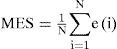
Where N is the total number of training patterns and “e” represents the error.
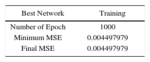
To train the RNAPM, 489 patterns were used. The learning method used was Batch, which defines the number of epochs representing the number of learning iterations; then, based on the training patterns known by the RNAPM, the mean-squared error is obtained, allowing to adjust the network weights until reaching the last epoch previously defined. The graph in Figure 5 shows the RNAPM training and a comparison between the value of learning epochs in the range of up to 1000 epochs and the mean-squared error value. Table 2 shows the resulting training values, like the minimum and final values of the mean-squared error.
3.4Nonlinear approximation
The RNAPM used in the proposed network topology constitutes an ideal approximation element to nonlinear behaviors, like the manipulation of a pneumatic artificial muscle-actuated robot arm, due to its generalization capacities, that is, its learning ability based on input and output data, defined as training evidence, and the nonlinear relation between them.
The RNAPM approximation technique consists of training the network with input and output values obtained from the PID control system described in Figure 3. Based on the same vector of input values used for training, the RNAPM has the capacity to propose the vector of output values representing the nonlinear approximation to the behavior learned at the training stage.
Figure 6 shows the behavior of the nonlinear approximation proposed by the RNAPM based on the training that used the PID control system behavior.

The evolution of the PID behavior defined by the angular error and the value of the angular position is equivalent to the evolution of the behavior of the proposed RNAPM topology, proving that this network is capable of approximating a nonlinear behavior like manipulating a McKibben pneumatic artificial muscle-actuated robot arm.
4Tests and resultsThe results obtained by the RNAPM up to the nonlinear approximation stage provide solid evidence of efficiency for being an equivalent behavior, according to the results depicted in the Figure 6 graph; however, at this stage it is not possible to determine if the RNAPM proposed values outperform the PID control behavior. To determine if the RNAPM is a better controller than the PID in a simulated environment, the network-proposed values were replaced within the control system, as shown in Figure 7.

The tests aimed to compare the efficiency of the PID control system against the RNAPM were carried out in the 5° to 55° range, at five-degree intervals.
Figure 8 below shows the result obtained from the PID and RNAPM controls at a 5° angular position, where the network is more efficient, resulting in a stabilization time of 3.8 seconds and no oscillations when compared with the PID control, which reaches stabilization at 5.8 seconds and oscillations of up to 0.001° at its highest level.

At a 15° angular position, another result was obtained, as seen in Figure 9, with the RNAPM again proving to be more efficient with a stabilization time of 3.25 seconds and no oscillations, compared to the PID control, which reaches stabilization at 4.73 seconds and oscillations of 0.027° at its highest level.

Figure 10 shows the result at a 30° angular position, the RNAPM control system proving to be more efficient, with a stabilization time of 3.1 seconds and no oscillations, compared to the PID control, which reaches stabilization at 4.5 seconds and oscillations of 0.17° at its highest level.

Figure 11 depicts the results at a 45° angular position, where a decrease of the RNAPM stabilization time is observed when compared to the PID control, which conversely requires more time to stabilize at the defined angular position.

In this test, the network achieves a stabilization time of 3.02 seconds and no oscillations, while the PID control reaches stabilization at 5 seconds with oscillations of 0.3° at its highest level.
Finally, Figure 12 shows the results of the test at 55° angular position, where the RNAPM stabilization time further decreases when compared to the PID control. In this test, the network achieves a stabilization time of 2.95 seconds and no oscillations, while the PID control reaches stabilization at 5.5 seconds with oscillations of 1.3° at its highest level.
5Conclusions
Based on the results obtained from the tests carried out in a simulated environment at an angular position range between 5° to 55°, the RNAPM proved to outperform the PID control system. A decrease of 2 seconds in the stabilization time and a 0.001° angular position minimization was observed at a 5° position, these numbers improving with each of the tests carried out at the defined range until reaching the final angular position of 55°, which resulted in a stabilization time of 2.95 seconds and a 1.3° error minimization. Furthermore, with its continuous, constant behavior, the RNAPM control system shows no oscillations.
It is therefore suggest that the neural network topology proposed is capable of learning a nonlinear behavior like that of pneumatic artificial muscle-actuated robot arms.
Future research work will include physical tests of the RNAPM control system on a one-degree-of-freedom SCARA robotic arm, built with an antagonist pair of pneumatic artificial muscles, in order to validate if the RNAPM shows the same efficiency in a real environment.
We would like to thank PROMEP [Program for the Improvement of the Faculty] for its support and sponsorship to carry out this research, which is part of the project “Study and Characterization of a Pneumatic Artificial Mini-Muscle Prototype under Static and Dynamic Conditions”, code ITTOL-PTC-002, from the call for proposals “Support to Admit New Full-Time Professors, Call for Proposals 2009”. We would also like to acknowledge DGEST’s support for the approval of the project “Prototype of a virtual system of a McKibben antagonist pair of pneumatic artificial muscle mini-actuators”, code TOL-DCIET-2010-102, which has been the basis to continue the research for this project.