


The main purpose of active-filter based power-quality improvement problems is to reduce the total harmonic distortion (THD) and improve power factor (PF) as much as possible. However according to standards such as IEEE-519/IEC 61000, selective harmonic distortion (SHD) should be controlled. The conventional power factor correction techniques, assume the voltage source to be purely sinusoidal. But it is rarely true because nonlinear loads draw nonsinusoidal current from the source and that causes a nonsinusoidal voltage supply applied to the load. Under such conditions, any attempt to make the power factor unity by usual methods will result into a nonsinusoidal current, which increases total harmonic distortion (THD). On the other hand, harmonic free current does not necessarily result in unity power factor because of harmonics present in the voltage. Therefore, there is a trade-off between improvement in power factor and reduction of THD. One of the best solutions for this trade-off is to optimize PF while keeping THD and SHD into their prespecified limits. In this paper five methods including shuffled frog-leaping algorithm (SFL), conventional PSO (C-PSO), linearly decreasing inertia PSO (LDI-PSO), type 1 PSO (T1-PSO) and constant inertia PSO (CI-PSO) are employed in order to optimize PF while restricting the THD and SHD within the inertia constant. In this work, the compensating current to be supplied by the shunt active power filter to the power system with these five optimization methods is applied and is observed using these evolution methods, PF has been improved considering all conditions. Also simulation results of a case study illustrate the high quality performance of SFLA among the algorithms used.
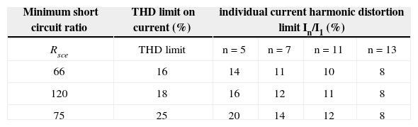
In the last few years, power electronic technologies have been developed extensively for various applications such as lighting, adjustable speed drivers, and uninterruptible power supply systems as consequence of advanced use of semiconductor devices. This power electronics equipment draws nonsinusoidal current and result harmonic distortion. In a power system, the harmonic distortion can be caused by the active and passive nonlinear devices. Nowadays, most harmonic distortion is generated by the input stage of (active) electronic power converters. Due to the nonlinear structure, most power electronics equipment draws nonsinusoidal current, and thus, results in significant harmonic distortion in the power system has severely deteriorated the power quality (PQ) in electrical power networks. Power quality has become a significant factor when differentiating between successful utilities in the power network specially deregulated environment [1]. Harmonic analysis is an important application to power systems as an efficient approach to evaluate the injected total harmonic distortion (THD). A method to manage the responsibility for harmonic distortion that can determine the contributions to harmonic distortion at the point of common coupling between a customer and a utility is presented in [2]. Because of the bad effect of harmonic distortion on power quality and importance of harmonics on the life span and performance of the equipment connected to the power system, regulatory agencies such as IEC and IEEE have specified limits for selective harmonic distortion (SHD) in addition to the THD. An optimal solution for a selective harmonic elimination pulse width modulated (SHE-PWM) technique suitable for a high power inverter used in constant frequency utility applications, is presented in [3]. According to IEEE Standard 519–1992 [4] and IEC 61000 (1998) [5], maximum allowable THD and SHD are limited for both voltage and current. The THD and SHD limits for current specified by IEC 61000 3–4 (1998) for a balanced 3-phase, low voltage component for a selected range is given in Table 1.
Current distribution limit for equipment (>16 A Per Phase)
| Minimum short circuit ratio | THD limit on current (%) | individual current harmonic distortion limit In/I1 (%) | |||
|---|---|---|---|---|---|
| Rsce | THD limit | n=5 | n=7 | n=11 | n=13 |
| 66 | 16 | 14 | 11 | 10 | 8 |
| 120 | 18 | 16 | 12 | 11 | 8 |
| 75 | 25 | 20 | 14 | 12 | 8 |
Note 1-The relative even harmonics shall not exceed 16/n(%)
To improve the power quality, several methods such as the use of higher-pulse converters; the modification of electric circuit configurations; the choice of transformer connections; and the application of harmonic filters have been proposed [6], [7]. Active power filters were developed for harmonic compensation and power factor correction [8]. In active filters, the compensation strategy is quite important and various strategies have been proposed to improve the performance of active filters [9]–[14]. Compensation strategies for control of shunt active filters are compared in [15].
A generalized and optimal control strategy (OFC) for harmonic compensation of utility lines is proposed in [16]. A simpler control scheme to generate the reference current for optimization of reactive volt-ampere or power factor subject to equality and inequality constraints imposed by harmonic conditions is proposed in [17].
In order to compensate harmonic distortion in current, different techniques have been reported using shunt active filters. Most of them assume a sinusoidal supply voltage and the goal is to achieve a sinusoidal source current. A few of these compensation techniques [16], [18], [19] have also considered the harmonics present in the supply voltage.
When the supply voltage is nonsinusoidal, any attempt to make harmonic free current results in reduction of power factor due to the harmonic present in the supply voltage. However, making the load voltage in phase and of the same shape as current may improve the power factor (PF), but the voltage distortion will be greater. Therefore, there is a trade-off between improvement in power factor and reduction in THD. Therefore, to solve this trade-off, it is necessary to optimize the PF and THD simultaneously. One solution is to optimize the PF while keeping THD within the limit. For a given active power, the PF can be improved by minimizing the total apparent input power S [20]. However, during this process some of the individual harmonics may exceed their limit. In [19], Lagrange function was used for the aforesaid optimization problem. Classical optimizations are limited to differentiable convex and continues algebraic objective functions and constraints and may depend on the specific function and/or constraints. On the other hand, due to the nature of these methods, they might converge to local solutions and fail to achieve the global one [21]. Furthermore, as the objective function complexity increases, these methods become more unreliable.
Recently, EAs such as genetic algorithms (GAs), particle swarm optimization (PSO), differential evolutionary (DE) and shuffled frog-leaping algorithm (SFLA), have made more contributions to solve optimization problem than other methods.
Although GA discovers the promising regions of search space quickly, it has two usual drawbacks: exploitation inability and premature convergence. PSO algorithm is a swarm intelligent technique inspired by food searching behavior of bird flocking [22]. This algorithm has been widely used in various fields of power system such as active power control, reactive power, and voltage control [23, 24]; power loss optimization [25] and voltage stability improvement [26]. PSO may be enormously affected by premature convergence and stagnation problem. DE algorithm is a simple population-based-evolutionary algorithm [27]. DE is also used to solve problems in power system [28, 29]. DE extracts the differential information (i.e., distance and direction information) from the current population of solutions to guide its further search. However, DE has no mechanism to extract and use global information about the search space [30].
In this paper, we proposed a new solution for control of selective and total harmonic distortion problem known as shuffled frog-leaping algorithm (SFLA). SFLA is a meta-heuristic optimization method based on observing and modeling the behavior of frogs. SFLA combines the benefits of the genetic-based memetic algorithms (MAs) and the social behavior-based PSO algorithm [31].
The rest of this paper is organized as follows: In Section 2, basic concepts for control of selective and total harmonic distortion are reviewed. Section 3 presents the mathematical formulation for control of selective and total harmonic distortion problem. In Section 4, SFLA optimization is described in detail. Simulation results and comparison with other algorithms are given in Section 5. Finally in Section 6, the conclusions are presented.
2Basic concepts and the proposed strategyThe proposed strategy calculates a reference current, which is used to produce the compensating current by the inverter.
Let us assume the supply voltage vs(t) contains a set of harmonic components, n1 that produce load current is(t) of the same frequencies and a further set of components, n2 that do not result in corresponding load current components. Also let the load contains a set of current components n3 due to its nonlinearity, having no corresponding frequency components in the supply voltage.
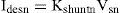
where Vsnand Isn are the rms value of the nth components of voltage and current, respectively, αn is the arbitrary angle of supply voltage and ψn is the phase angle of nth harmonic component of voltage. In this paper, a shunt active filter is used for limiting the SHD and THD in current. In order to achieve unity power factor, currents drawn should be of the same shape as source voltage and in phase with it (ψn should be zero). Also the harmonics in voltage and current should be of the same order and their ratios should be equal. Hence, the desired source current ides*(t) may be written as where Idesn is the rms value of the nth harmonic component of the desired source current and could be written as where Kshuntn is the control variable defined as the admittance of the compensated load with shunt active filter.


Similarly, a series active filter can be used for the compensation of voltage harmonics. Let us assume that the current (2) is in phase with the supply voltage (1). The desired load voltage vdes * is computed in a similar way as (3) and can be written as:
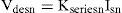
where Vdesn is the rms value of the nth harmonic component of the desired load voltage and can be written as: where Kseriesn is the control variable defined as the impedance of the compensated load with series active filter.
By controlling Kshuntn and kseriesn current THD and SHD and also power factor are controlled. kshuntn, is calculated in Section 3 by using PSO and SFL optimization techniques.
3Problem formulation3.1Objective function (f)As mentioned before, for a given active power, the PF can be improved by minimizing the total apparent input power (S) [20]. In this study S is taken as the objective function. The power circuit of the scheme consists of a three-phase nonsinusoidal supply voltage connected to an unbalanced non-linear load that is shown in Figure 1. The apparent input power (Sa) for phase a is constructed using (1) and (3) as follows:
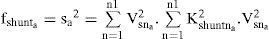
where Vsna and Idesna are the rms value of the nth components of voltage and desire current of the phase a, respectively. On substitution for Idesna=Kshuntna.Vsna, the objective function (fshunta) for a shunt active filter is given by: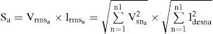

On similar substitution for Vdesna=Kseriesnaa.Isna, the objective function (fseries) for the series active filter can be formed as
where Isna and Vdesna are the rms value of the nth components of load current and desire load voltage after compensation of the phase a, respectively. The purpose of optimization is to minimize the apparent power. However, this optimization comes along with the satisfaction of two constraints. To meet the constraints in this problem equality and inequality constraints are applied using penalty factors as discussed in the following Subsection.3.2Equality constraints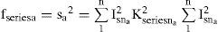
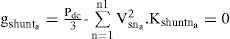
The equality constraint is formed by applying the condition that the mean value of instantaneous power, before and after compensation, should be the same. When the displacement angle between the voltage and current is zero after compensation, the mean value of the instantaneous real power of “phase a” is given by:
hence, for a shunt active filter, the equality constraint (gshunta) is given by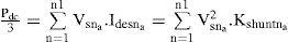
Similarly, for a series active filter, the equality constrain (gseriesa) is written as :
3.3Inequality constraints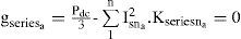
Two inequality constraints should be considered. SHD and THD in current and voltage in the case of series active filter should be within the specified limits.
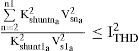
3.3.1Inequality constraintsLet the total current harmonic distortion be limited to ITHD. The inequality constraint for the shunt active filter (ushunta) is given by:

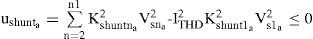
Similar expression can be obtained for a series of active filter by assuming that the total voltage harmonic distortion be limited to VTHD as follows:
3.3.2Selective harmonic distortion (SHD)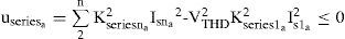
Let the hth order current harmonic component be limited to ISHDh. Then the inequality constraint for the shunt active filter (wshunta) can be determined as below

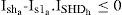

Similar expressions can be obtained for a series of active filter by assuming that the hth-order voltage harmonic component is limited to VSHDh as follows:

Now that the constraints are described, the objective function for shunt active filter can be defined as follows:
where λgshunta, λushunta and λwshunta are the penalty factors.4Shuffled frog-leaping algorithm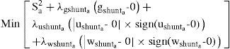
The SFL algorithm originally developed as a population-based metaheuristic to perform an informed heuristic search using mathematical functions to find a solution of a combinatorial optimization problem [24]. It combines the benefits of both the genetic-based memetic algorithm (MA) and the social behavior-based particle swarm optimization algorithm [24].
In SFL algorithm, there is a population of possible solutions defined by a set of frogs that is divided into subgroups called memeplexes, each performing a local search. After a defined number of memetic evolution steps, ideas are passed among memeplexes in a shuffling process. The local search and the shuffling process continue until the defined convergence criteria are satisfied [32].
At first, an initial population of P frogs is created randomly within the feasible space. For an S variable problem, ith frog is represented as Xi=(xi1, xi2… xiS). Then, the frogs are sorted in a descending order according to their fitness. Then, the whole of population (P) is separated into m memeplexes, each containing n frogs. In this procedure, the first frog moves to the first memeplex, the second frog moves to the second memeplex, frog m moves to the mth memeplex, and frog m+1 goes back to the first memeplex, etc.
Within each memeplex, position of frogs with the best and worst finesses is determined as Xb and Xw, respectively. Also, the position of a frog with the global best fitness is determined as Xg. Then, in each memeplex, a process is applied to improve only the frog with the worst fitness (not all frogs) in each cycle as follows:
where Rand() is a random number between 0 and 1. If this process generates a better solution, the worst frog will be replaced. Otherwise, the calculations in (22) and (23) are repeated with replacement of Xb by Xg. If no improvement becomes possible in this case, then a new solution is randomly generated within the feasible space to replace the worst frog. Then, the calculations continue for a specific number of iterations [32].
After a pre-specified number of memetic evolutionary steps within each memeplex, to ensure global exploration, ideas passed within memeplexes are combined in the shuffling process [24]. The local search and the shuffling continue until convergence criteria are satisfied. Figure 2 shows the main idea of this algorithm.
5Case study
In order to verify the algorithm for total and selective harmonic control using shunt active filters, the same balanced, 3-ϕ, 4-wire, 415-V, 50-Hz, trapezoidal voltage supply, having 21.02% THD and 20.5% third harmonic distortion is considered as [19]. To verify the performance of the algorithm, simulation studies have been carried out for the following cases:
Case 1. Verification of the algorithm to limit THD and SHD in current per IEC-61000 3–4 by using a shunt active filter.
Case 2. Capability of the algorithm to limit even harmonic distortion in current, using a shunt active filter.
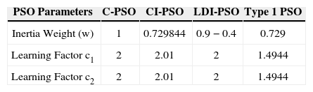
5.1Simulation setupThe evolutionary algorithms applied for comparison are conventional PSO (C-PSO), inertia constant PSO (CI-PSO), linearly decreasing inertia PSO (LDI-PSO), type 1 PSO [33–36] and SFLA. Table 2 shows the parameters of these algorithms. Maximum number of iterations for all of algorithms is set to 100. In SFLA and NM-SFLA, the number of iteration for each memeplex is set to 10. Regard to the randomness of the heuristic algorithms, many trials with different initializations should be made to prove if the algorithm is robust. For each algorithm, 50 independent trials are made. The population size (number of particles of different types of PSO), the number of memeplexes in SFLA and the number of frogs in each memeplex are respectively set as: 70, 5 and 14.
5.2Case 1In this case, according to IEC 61000 3–4 (1998) shown in Table 1, the fifth harmonic distortion (ISHD5) and THD (ITHD) in the source current must be limited to 14% and 16% respectively using a shunt active filter. A combination of 3-φ resistive networks and 3-φ diode rectifiers act as the load which consumes around 55-kw power.
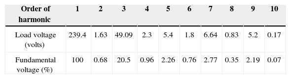
Waveforms of the nonsinusoidal load current and supply voltage for “phase-a” of the sample power system considered are shown in Figure 3[19]. Table 3 shows the computed values of the individual harmonic distortion and magnitude of harmonic components of the supply voltage before compensation. The current THD is 25.67%, which is greater than ITHD (limit)=16%, and the PF of the circuit before compensation is 0.95. Figure 4 (a and b), shows the harmonic spectra of the supply voltage and source current (the same as load current) before compensation. The current spectrum in Figure 4 (b) shows that the fifth harmonic component is predominant and the THD is 25.67%.
 and load current (ila) before compensation (current THD=25.67%, fifth harmonic component of current=16.83%, and PF=0.953")
 Harmonic spectra of supply voltage and source current before compensation for Case 1")
Therefore, according to the standard in Table 1, the THD as well as the SHD in current exceed their limits.
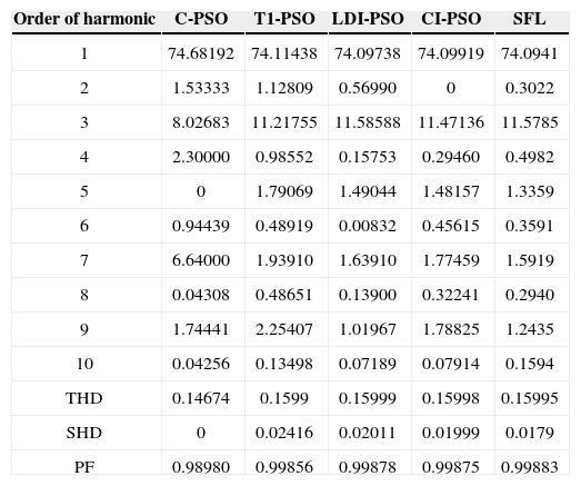
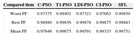
The results of five optimization methods that are used in this paper are shown in Table 4. As this table illustrates, in all cases THD and SHD are within their limits and PF was improved after compensation. SFLA finds the minimum value for objective function and hence, maximum value for PF compared with other methods and improved PF from 0.953 before compensation to 0.99883. The convergence characteristics of different algorithms are shown in Figure 5. As mentioned before, many trials with different initial values should be done regard to clarify the reliability of an EA. The performance comparison for the algorithms used after 50 independent runs, is shown in Table 5. This table depicts the ability of SFLA in providing high quality solutions in many trials. Harmonic spectrum of the resulting source current after compensation using SFL method is shown in Figure 6.
Computed values of harmonic component of load current after compensation for Case 1
| Order of harmonic | C-PSO | T1-PSO | LDI-PSO | CI-PSO | SFL |
|---|---|---|---|---|---|
| 1 | 74.68192 | 74.11438 | 74.09738 | 74.09919 | 74.0941 |
| 2 | 1.53333 | 1.12809 | 0.56990 | 0 | 0.3022 |
| 3 | 8.02683 | 11.21755 | 11.58588 | 11.47136 | 11.5785 |
| 4 | 2.30000 | 0.98552 | 0.15753 | 0.29460 | 0.4982 |
| 5 | 0 | 1.79069 | 1.49044 | 1.48157 | 1.3359 |
| 6 | 0.94439 | 0.48919 | 0.00832 | 0.45615 | 0.3591 |
| 7 | 6.64000 | 1.93910 | 1.63910 | 1.77459 | 1.5919 |
| 8 | 0.04308 | 0.48651 | 0.13900 | 0.32241 | 0.2940 |
| 9 | 1.74441 | 2.25407 | 1.01967 | 1.78825 | 1.2435 |
| 10 | 0.04256 | 0.13498 | 0.07189 | 0.07914 | 0.1594 |
| THD | 0.14674 | 0.1599 | 0.15999 | 0.15998 | 0.15995 |
| SHD | 0 | 0.02416 | 0.02011 | 0.01999 | 0.0179 |
| PF | 0.98980 | 0.99856 | 0.99878 | 0.99875 | 0.99883 |


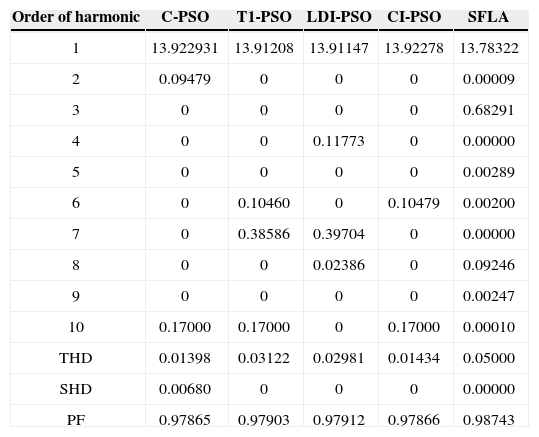
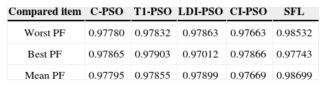
The proposed algorithm is also verified for limiting current THD (ITHD) to 5% and the second harmonic distortion (ISHD2) in the source current to 3% using the shunt active filter. Considering the severe impact of even harmonics on the system, IEEE 519 requires that even harmonics be limited to 25% of the odd harmonic limit. The harmonic spectra of load current (for case 2 before compensation), is shown in Figure 7. In this case, a half-wave rectifier load of 10kw is connected to the same supply as considered in Case 1. As shown in Table 6, it is observed that all methods increase PF better than [19] that improved PF from 0.808 to 0.986. As the previous case, best results are achieved from SFL that improved PF from 0.808 to 0.9874 due to the use of an efficient penalty parameters method for constraint handling. Harmonic spectrum of the resulting source current after compensation using SFL method is shown in Figure 8. The performance comparison for the algorithms used after 50 independent runs are shown in Table 7. The convergence characteristics of different algorithms are shown in Figure 9.

Computed values of harmonic component of load current after compensation for Case 2
| Order of harmonic | C-PSO | T1-PSO | LDI-PSO | CI-PSO | SFLA |
|---|---|---|---|---|---|
| 1 | 13.922931 | 13.91208 | 13.91147 | 13.92278 | 13.78322 |
| 2 | 0.09479 | 0 | 0 | 0 | 0.00009 |
| 3 | 0 | 0 | 0 | 0 | 0.68291 |
| 4 | 0 | 0 | 0.11773 | 0 | 0.00000 |
| 5 | 0 | 0 | 0 | 0 | 0.00289 |
| 6 | 0 | 0.10460 | 0 | 0.10479 | 0.00200 |
| 7 | 0 | 0.38586 | 0.39704 | 0 | 0.00000 |
| 8 | 0 | 0 | 0.02386 | 0 | 0.09246 |
| 9 | 0 | 0 | 0 | 0 | 0.00247 |
| 10 | 0.17000 | 0.17000 | 0 | 0.17000 | 0.00010 |
| THD | 0.01398 | 0.03122 | 0.02981 | 0.01434 | 0.05000 |
| SHD | 0.00680 | 0 | 0 | 0 | 0.00000 |
| PF | 0.97865 | 0.97903 | 0.97912 | 0.97866 | 0.98743 |


In this paper, SFLA, conventional particle swarm optimization and three of its versions were used in order to improve PF while limiting the total and individual harmonic distortion in current or voltage under nonsinusoidal supply voltage and current conditions, using a shunt active filter. An important feature of these algorithms, is that it is also possible to change the objective function or equality constraints as per the requirements with good accuracy, especially by using SFLA for the optimization problem, best results were achieved. To demonstrate the applicability of the proposed algorithm, simulation is carried out on the same supply and cases with [19] and observed that both PF and THD became better.