


A cost-effective direct liquid injection system is developed for a chemical vapor deposition process using a microcontroller. The precursor gas phase is controlled by the precise sequential injection of a liquid precursor solution to a vaporizing chamber prior deposition. The electronic control system allows the human–machine interface through a LCD display and a keypad matrix. The core of the electronic system is based on an electro mechanical injector operated in time and frequency as a sequential control system by a popular PIC16F877A chip. The software has been developed in the BASIC language and it can be easily modified through an ICSP programmer for different sequential automatized routines. The injection calibration test has proven the linearity of the injection control system for different operation parameters. The results reported the sequential injection MOCVD deposition of alumina thin film.
Metal organic chemical vapor deposition (MOCVD) is an important technique for the synthesis of materials in the form of coatings and thin films for the electronics and semiconductor industry. This process, allows depositing solid materials in the form of thin films and powder from a metal-organic precursor by mean of a chemical reaction on a thermally activated surface.
Usually, metal organic precursors do not have enough vapor pressure for being effectively transported to a thermally activated surface; when the precursor reaches the sample, it decomposes to produce a desired material in the form of thin film. In order to increase the vapor pressure, precursors must be heated to increase their volatility and transported by means of a carrier gas. The heating and cooling process of the precursor in sublimation and bubbler technologies have some drawbacks. Precursors can partially decompose after thermal cycles, reducing the reproducibility of the thin film deposition process (Sovar Samélor, Gleizes, & Vahlas, 2007). The gas phase concentration is variable in time due to its difficult control, and this is because temperature and mass flow variables are coupled in a same device. Moreover, the evaporation rate also fluctuates in time; it has a strong dependence on the remaining amount of precursor in the container.
Direct liquid injection arises as an important technique which can reduce intrinsic drawbacks of conventional precursor delivery methods. In this sense, if a constant vapor precursor concentration can be reached, conformal smooth thin films can be produced with this method; the process can be transferred to academic and research environments to satisfy industrial applications. As the precise control of the main variables for the MOCVD process is a key factor in order to obtain high experimental reproducibility, precise control of the precursor flow becomes one of the more relevant issues which must be treated efficiently; in this way, direct liquid injection MOCVD has proved to solve this problem showing good results to deposit some oxides (Mungkalasiri et al., 2009; Na, Kim, Yong, & Rhee, 2002).
The direct liquid injection technique allows reducing the drawbacks related with the bubbler and sublimation-based technologies. With this technology, a micro amount of the precursor solution is atomized and heated in a vaporizing chamber in order to be immediately released to the reactive zone where the deposition takes place. The precursor solution is pressurized under an inert atmosphere in order to avoid contact with the air and moisture which could lead to a premature reaction and aging, moreover the precursor solution is maintained all the time at room temperature just an instant before being atomized and released. In this manner, there is not enough time for the precursor to present chemical changes. The micro amount is controlled electronically by the opening time and frequency of the injector, by this way is possible to maintain a more stable and constant precursor vapor flow into the reactor chamber, with these characteristics, is possible to increase the reproducibility of the experiments and operate the system in a safer and convenient way.
The atomic layer deposition processes has also already taken an advantage of this delivery precursor method producing high quality thin films (Leskelä & Ritala, 2002). A precise amount of precursor is injected sequentially for each cycle; the growth is constant and complex structures can be obtained (George, 2010). In this context, the microcontrollers are useful electronic devices which can be adapted for chemical laboratory facilities for monitoring and control of dedicated processes. The low cost and high availability of such devices allows the development of electro mechanical systems for analytical instrumentation in academic and research environments (Kubínová & Šlégr, 2015; Rajendran & Neelamegam, 2004; Ramana & Malakondaiah, 2007; Urban, 2014, 2015).
The present work is dedicated to the development of a low cost sequential microcontroller-based direct liquid injection control system based on a PIC16F877a microcontroller. This system can be used in a direct liquid injection MOCVD reactor to produce coatings, thin films and nanostructures. The microcontroller and the electro mechanical injector are coupled through a power electronic stage. The microcontroller control contributes to the improvement in the repeatability accuracy of the thin film deposition process; moreover, the microcontroller interface via a matrix keyboard and LCD allows changing the injection parameters in real time through automated sequential routines.
2Design schemeThe core of the injection control system is a Pic16F877a microcontroller. The design scheme is shown in Figure 1. This microcontroller has been selected because of its low cost, high availability and friendly user programming tools. This CMOS FLASH-based 8-bit microcontroller has 5 ports with embedded peripherals such as ADC, timers, USART and longtime data retention around 40 years. These functionalities make of this microcontroller an attractive device for this application.

Block B contains the user interface to the data input to the controller by means of a keypad which allows selecting the time and frequency desired to the operational parameters of the injector. The selection of an operation routine can be modified at any time during the processing if desired. If it is desired to obtain a constant gas phase feeding to the reactor, the routine must be kept constant, which makes it possible to obtain conformal smooth thin films. If it is desired to modify the reaction ration rate through a gas phase modification, the routine can be modified, in fact automated routines can be programmed to obtain different growing rates in a reproducible way. Several injectors can be combined with a wide spectrum of injection parameters to obtain new complex materials with unique electrical, chemical, and mechanical functionalities. For this reason, the time-on and frequency of operation parameters are crucial for this process. In this sense, with this control system the gas phase can be precisely controlled and each combination can modify the gas phase through the reaction chamber and modify velocity and concentration profiles to finally modify the reaction rate to deposit from single to complex coatings and thin films. The block D contains a power electronic stage which transfers the control signal processed from the microcontroller to the injector. The core of this stage is an electro mechanical injector. For the correct atomization of solutions, the injector must be kept at 40psi. The control signal is transferred to the injector through a power MOSFET IRL510 which is a low cost, fast switching device for inductive loads. The system has been successfully tested from shorts injection parameters, such as time-on of 5ms and 0.5s of frequency. The block C is composed of a LCD 12X2 alphanumeric low cost display, which allows to see the injection parameters operating on real time. Because of the ICSP (in-circuit serial programming) option in this microcontroller, injections routines can be easily modified.
2.1Circuit descriptionThe circuit diagram of the injection control system is shown in Figure 2. The keypad consists of a matrix of logic buttons embedded in the same device. Usually one port is needed to read an input, but with this configuration, a reduced number of ports and components are needed to input data for the microcontroller.

As it is shown, 8 pins of Port D are needed to read up to 16 combinations from the 4x4 keypad, in this case 7 pins are used for reading 12 buttons (RD0-RD6). The LCD transference has been assigned through the port A for convenience (RA0-RA4). In Port B just two pins have been assigned, RB3 which allows enabling the communication between the LCD and the microcontroller, pin RB0 is assigned to the control signal to the gate of the power MOSFET stage of the injection system. The IRL510 MOSFET allows controlling the inductive load of the electromagnetic injector. This device is capable of handling up to 5A peak output current, large enough for the injection power supply. This configuration enables a safe operation and over temperature protection, making of this control system a long-term safe operation, although fast switching during injection operation during long term time with short time-on (2ms), high current peaks (1.2A) for the inductive load of the injector are well supported with this configuration. A 4MHz micro crystal is connected to pins 13 and 14, respectively. The circuit is built with just a few microelectronics and discrete components for a very low price (<100 USD) in comparison with the expensive specialized equipment sold by large companies. This is a cost-effective approach which can operate this process in an easy and efficient way.
2.2SoftwareThe program has been developed using BASIC. Ports A and B have been selected as output to the LCD and the injection control pin. Bits D3–D6 have been selected as inputs in order to be read by the microcontroller and read keypad state. A variable has been initialized in order to store de data obtained by the keypad reading. A set of conditional control sentences “if” have been nested in order to define the injection parameters, time on and frequency that the injection must to operate for each button. The compiled .HEX program has been transferred to a section of the Pic16F877a using the ISCP programming protocol and a low cost programmer (K150). This program allows having the whole set of operations for the injector. The diagram flow chart is shown in Figure 3.
3Materials, methods and injector calibration
The mechanical components of the injector head have been machined in aluminum 6061 and nylamid™. The base which supports the injector is connected to the vaporizing chamber and it has been built also in aluminum 6061 because of its mechanical and thermal properties. Aluminum has enough strength to support the injector and the thermal dissipation; also, it reduces the need for an electric fan which must cool the injector. Two rods have been machined for this purpose. The plate has a fast connector for polyurethane flexible transparent pipe which transports the solution from the pressurized container to the injector feeding head, as it can be seen in Figure 4.

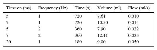
In order to calibrate the injector, 5 routine parameters have been selected. Water has been selected as the calibration solution. The line pressure has been set to 40psi for all the runs. The calibration set-up is shown in Table 1.
4Thin film characterizationThe results obtained using the system is focused on the MOCVD thin film deposition. The thin film precursor used for this experimental set-up was aluminum tri-sec-butoxide (Sigma Aldrich) diluted in cyclohexane (Sigma Aldrich). This precursor results convenient for the pulsed injection chemical vapor deposition, it is liquid at room temperature. Before deposition, silicon samples were cleaned using an isopropyl alcohol ultrasonic bath for 5minutes and dried in argon flow. The thin film precursor had been sequentially injected to a vaporizing chamber with a digital temperature controller set to 140°C. The thin film deposition took place in a hot-wall reactor which was composed of a thermo regulated quartz tube. Temperature had been regulated using a resistive load coupled to a digital controller. Thin film deposition took place around 350°C. Figure 5 presents an optical micrograph of the surface, as can be observed; although thin films were deposited on silicon substrates, deposition on stainless steel 304L sample holder results interesting, any kind of special preparation had been done for this material, the sample holder had been just cleaned using isopropyl alcohol prior to deposition and further characterization for this material will be prepared for a forthcoming manuscript. There exists an increasing interest of alumina protective properties for stainless steel in corrosion applications. The thickness of the silicon sample is 1mm; as shown in Figure 5, this dimension is large enough to modify the flow precursor patterns and, consequently, the deposition path.

The chemical vapor deposition technique takes advantage of this situation; using computational fluid dynamics software is possible to predict the precursor flow behavior in the reactor under controlled environments; deposition thickness and precursor mass fraction can be computed to predict the deposition rate for complex shapes obtaining close results between computational and experimental results (Vergnes, Samélor, Gleizes, Vahlas & Caussat, 2011). The surface morphology of thin films has been investigated using the scanning electron microscope technique as shown in Figure 6.
 and energy dispersive X-ray spectroscopy (b) analysis of the thin film deposition on silicon sample.")
The same image/position has been used for the energy dispersive X-ray spectroscopy mapping analysis in order to investigate the elemental composition/distribution of the sample, as shown in Figure 6. It can be seen that the film does not have trenches or blotches, as can be observed, a crack free surface without pores and pinholes has been obtained. On the other hand, at the sample surface is possible to observe nodules which could be formed because of homogeneous gas phase reactions under the conditions of this process.
The elemental analysis energy dispersive X-ray spectroscopy at the sample surface shown in Figure 6 revealed a distribution of carbon, oxygen and aluminum elements in the sample. The silicon signal corresponds to the substrate. With these results, it is possible to suppose as a first assumption an alumina thin film formation in agreement with reports in the literature presenting aluminum tri-sec-butoxide as an alumina thin film precursor (Haanappel, Van Corbach, Fransen, & Gellings, 1994). The local distribution of the elements is homogenous at the surface, as shown in Figure 6, but higher aluminum concentrations are present at the surface nodules; this could be attributed to gas phase reactions or, ultimately, to an incomplete precursor decomposition path during thin film formation
5Results and discussionThe performance of a microcontroller-based injection control system was investigated using distilled water in a pressurized container at 40psi pressure. The solution consumption was read before and after for each run. As it can be noted, the injection performance is quite linear in relation to the different injection parameters adopted for the flow as shown in Figure 7.

The time parameter determines how long the valve remains open and the frequency determines how many times the valve is opened during one second. In Figure 7 it is possible to see that the three flows obtained from calibration have a quasi linear relationship. As can be noted, the sequential injection control system operates in an efficient way, as it can achieve constant flow during time for the injection of each parameter set. In order to increase the flow to a reactor chamber there exist two possibilities:
- (a)
Increasing the opening time for the injector with a constant frequency
- (b)
Increasing the frequency of pulses per seconds with a constant opening time.
The increase of the opening time of the valve seems to be a more reliable choice, as an increase of the frequency reduces the time-life of the injector.
6ConclusionThe injector calibration test has shown that it is possible to determine the flow for each injection parameters for any particular liquid/solution. During a direct liquid injection chemical vapor deposition test, the solution, which is usually formed from a solid/liquid precursors dissolved in an organic solvent, the calibration method must be done for each particular solution because of the changes in viscosity, density and physical properties of the liquid which can modify the flow rate for each injection parameters. The sequential injection control system has an acceptable precision; it aims to obtain a constant vapor gas phase to feed the chamber of a chemical vapor deposition process for conformal thin film deposition. The precursor solution used with this system has led to alumina thin films formation on silicon and 304L stainless steel samples. This work has revealed an excellent cost-effective alternative for direct liquid injection chemical vapor deposition processes.
Conflict of interestThe authors have no conflicts of interest to declare.
The authors are grateful for the support to conduct this work granted by CONACYT and SIP-IPN.
Peer Review under the responsibility of Universidad Nacional Autónoma de México.