


In this paper we proposed a method for geometric calibration of a projector. This method makes use of a calibrated camera to calibrate the projector. Since the projector works inversely with a camera i.e., it projects the image instead of capturing it, so it can be considered as a reverse camera. The projector is calibrated with the help of a calibrated camera using two types of chessboard, a printed chessboard and a projected chessboard by the projector. The object points of the projected chessboard pattern are measured with the help of calibrated camera and the image points are directly acquired from the chessboard pattern to be projected. Then using these object points and image points the projector is calibrated. Once the projector calibration is done, the transformation matrices (from projector to screen, from camera to screen and from camera to projector) are determined which are used for the reconstruction of the 3D geometry.
The 3D shape measurement and reconstruction has become one of the hottest fields in computer vision and robotics during the past few years. Researchers from various fields like computer vision, robotics, mechatronics, intelligent manufacturing systems and applied optics have worked enormously to find more robust, less complex and faster techniques [1, 2]. These techniques are being adapted for medical, rapid prototyping, defense and other numerous industries. Based on their characteristics, these techniques are divided into two subgroups. The first one includes the use of stereovision system. This system makes use of two cameras to measure and recover the 3D geometry. The images of the objects are taken by both cameras from different positions and orientations simultaneously. Triangulation is then used to measure the 3D geometry. The bottle neck in the stereovision system is the correspondence. That is, to find the corresponding points in the projection of the scene in one camera to the points in the other camera. To cop with the correspondence problem, various image processing techniques are used. The correspondence problem is not involved in the second method. In this method the projector projects a structured light on a 3D geometry which is captured by a single camera. During the past few years a lot of work has been done on this technique and many people have come up with some very diverse ideas. This technique of reconstructing and measuring the 3D geometry is faster, robust and inexpensive; especially these days the decreasing prices of projectors and CCD camera has made it easy to have a 3D measurement system. But before doing any re-construction and measurement process the projector and the camera system must be calibrated. Researchers have investigated camera calibration deeply thus, there are different algorithms for this purpose.
For projectors there are two kinds of calibrations: The photometric calibration and the geometric calibration. The photometric calibration deals with the intensity values correspondence of the projected images and the images captured by the camera. This research focuses on the geometric calibration of the projector which deals with the calculation of the intrinsic and extrinsic parameters of the projector. Many researchers have worked on the geometric calibration of the projector.
Zhang and Huang [3] came up with the idea of capturing images with a projector. The projector is used to capture images like a camera, in this way the projector can be calibrated like a camera. The main difficulty lies in making the special setup of white and red light illumination. Apart from this detailed calculations, to find the absolute phase map make it a math heavy and time consuming method. Li and Shi [4] also proposed the calculation of the DMD image i.e., the image taken by the projector and make use of vertical and horizontal fringe patterns to recover the points seen by the projector, thus making it a time consuming method too. Gao and Wang [5] have done the projector calibration using homographies. That is a nice idea too but the problem is with the red and blue pattern they used like Zhang and Huang. They also use a very big chessboard pattern for which a camera with wide FOV is needed. A wide FOV results in the image distortion.
Because much work has been done, by researchers on camera calibration, in this work the projector calibration for the 3D measurement system is done based on the principles of the camera calibration.
The rest of the paper is arranged as follows; Section 2 describes the basic concept of camera calibration and how is it done in OpenCV. Section 3 sheds some light on projector calibration. Section 4 gives the 3D shape measurement system setup. Section 5 gives the results of experiments and their verification in OpenCV and finally the conclusion and future work are given.
2System model2.1Problem statementLet us consider a point (mpro, npro)T in the projector's plane. This point is projected on an unknown 3D point (Xw, Yw, Zw)T in the world plane. The camera then takes the image of this point and as a result the point (mcam, ncam)T is obtained in the camera's image plane. It can be observed that the projector acts as a reverse camera. The camera takes an image of the unknown point on the screen while the projector projects the known point onto an unknown point. Here the divided and conquer rule can be applied to solve the problem. The whole process can be divided into two parts.
- 1)
The projector to the screen
- 2)
The screen to the camera
A lot of work has been done on camera calibration during the past decades. The latest method that is used by most of the researchers is Zhang's. This method uses pinhole camera model, which has focal length, pixel size, and skews factor as intrinsic parameters and the translation and rotation of the camera reference frame with respect to the world reference frame as extrinsic parameters. The calibration is simply a process that finds the intrinsic and extrinsic parameters of the camera. A brief description of Zhang's method follows.
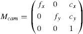
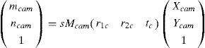
This method uses a regular shaped object e.g., a chessboard pattern. Let qcam = (mcam, ncam, 1)T be the 2D point in the image plane and Qcam(Xcam,Ycam,Zcam,1)T be the corresponding 3D point in the screen frame of reference. According to the pinhole camera model
In Equation 1. Mcam is the set of intrinsic parameters and (Rcam/tcam) is the set of extrinsic parameters. ‘s’ is an arbitrary scaling factor. The set of intrinsic parameters is given as:where fx and fy are the components of focal length in x and y co-ordinates. (cx,cy) are the co-ordinates of pricipal focus. It is assumed that the model plane is at Z=0, hence, Equation 1 becomes:where [r1c r2c tc] is the extrinsic parameters matrix. More details of the method can be found in [4].
The summary of the method is as follows:
- 1.
A regular-shaped object like a chessboard is attached to a flat and smooth sheet of plastic.
- 2.
Images of the object are taken at different positions and orientations.
- 3.
The feature points in the image are detected by a special function in OpenCV and stored in a matrix called the ‘image points’.
- 4.
The object points are also stored in another matrix called the ‘object points’.
- 5.
Both matrices are provided to the main calibration function in OpenCV to find the intrinsic and distortion parameters of the camera.
- 6.
The set of extrinsic parameters of the camera is then determined with the help of the intrinsic parameters.
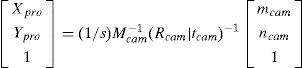
Given that the projector can be considered as the inverse of a camera, the pinhole model also applies to the projector. The difference is that the camera captures the image of the screen while the projector projects the image to the screen. The projector can also be calibrated as the camera with the help of Zhang's method. If the object points of the pattern that is projected by the projector on the screen and the image points of the same pattern are known, then the calibration function in OpenCV can calculate the intrinsic parameters of the projector. The main problem here is that the object points are unknown. To find the object points the calibrated camera can be used. The camera can calculate the 2D object points (as we considered Z=0) on the screen and the image points can be directly read from the image that the projector is projecting. According to pinhole camera model,
In Equation 4qpro can be directly read from the image that the projector is projecting. For the measurement of the object points Qpro the calibrated camera can be used in the following manner.
A special set up of chessboard is used. The printed chessboard is attached to a flat sheet of plastic and then covered with a thin sheet of paper as shown in Figure 1. The printed sheet is attached to the plastic sheet from the upper side so that it can be moved freely.

For each position two images are taken. The first image is that of the printed chessboard. For the second image the printed chessboard is covered with the sheet and the chessboard image from computer, is projected by the projector. The image of the projected chessboard is then taken with a camera. The whole process is summarized in the following steps:
- 1.
Take the image of the printed chessboard.
- 2.
Cover the printed chessboard with the sheet and project the chessboard from the PC to take the second image.
- 3.
Calculate the extrinsic parameters using the printed chessboard with the help of the calibrated camera.
- 4.
Calculate the corners of the projected chessboard with the help of the extrinsic and intrinsic parameters of the camera and store in the ‘object points’ matrix.
- 5.
Detect the corners in the image of the chessboard that is projected by the projector and store in the ‘image points’ matrix.
- 6.
Move to the next position and repeat steps 1 to 5.
- 7.
Having enough image and object points, feed both matrices to the calibration function of OpenCV to calculate the intrinsic parameters and distortion parameters.


At this stage the intrinsic and distortion parameters of both the camera and the projector are known, this is the exact stage of setting up the 3D shape measurement system. To do this, the relative position of camera and projector need to be set with respect to a world coordinate system. This is done with the help of the same chessboard pattern. The projector is placed perpendicular to the screen and the chessboard is projected on the screen. The upper left corner of the projected chessboard is set as the origin of the screen reference plane. The x-y axes are on the plane and z-axis is perpendicular to the plane. The origin is selected due to the fact that OpenCV start detecting the corners from that corner. The set up of the system is shown in Figure 2 along with the x,y and z axes of the camera, projector and screen reference planes and transformations between these planes. Figure 4 shows the setup used in this research.
5Experiments, results and verifications
In this work the IDS uEye ® CCD camera was used. The resolution of this camera is 1024×768. The LCD projector used is EPSON EB-1735W with a resolution of 1024×768. The set of intrinsic and extrinsic parameters of the camera and projector are given.
Camera intrinsic and extrinsic parameters
Intrinsic parameters:
Extrinsic parameters: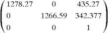
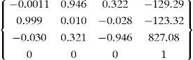
Projector intrinsic and extrinsic parameters
Intrinsic parameters:
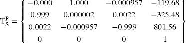
Extrinsic parameters:Transformation matrix from camera to screen: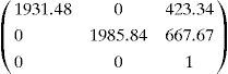
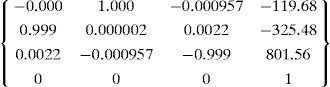
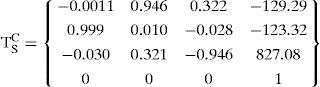
Transformation matrix from projector to screen:
A 3D to 2D point projection method is used for the error analysis of the proposed method. This method of error analysis is also known as the re-projection error analysis. In this method known-object points such as the corners of a chessboard are projected onto the image plane by applying the known intrinsic and extrinsic parameters of the projector. These are called the “calculated image points”. Also the image points are read directly from the image to be projected by the projector. These points are called the “measured image points”. The corners of the projected chessboard are measured in two different ways. They are measured with calibrated camera and with a graph paper. These measured corners are the “measured object points”. The measured object points and the calibrated projector are then used to calculate the image points according to the following equation:
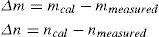
The whole scenario is shown in Figure 3. Let qcal(mcal,ncal) be the calculated image point according to Equation 8 and qmeasured(mmeasured,nmeasured) be the point measured i.e., directly read from the chessboard image to be projected by the projector.
![Known chessboard projected by calibrated projector [7]](https://static.elsevier.es/multimedia/16656423/0000001200000001/v2_201505081640/S1665642314716086/v2_201505081640/en/main.assets/gr3.jpeg?xkr=ue/ImdikoIMrsJoerZ+w997EogCnBdOOD93cPFbanNcX6PcOHo8VDqRKrp6xHZ/NlPxKUvo805ICrHlplwxcm7hYIESfjCCTNDlVokL+8rO+IjstvoljemVr146+MpGmO0RXOBQm7AhpL6ziGtIim2qDKscDjR7zR6bL+jfnFwXTxeS+sf9fGexUq6N36TYoLQlGGogNERQup1MVXeVqCS2buBDxzel+mniAckSoxqHBXL4p/qijHDcnmgLruQrN/M7Ko4SULewfmZsjl9tO+tSeHB/qCtNEgMQZ6DHZ8jOIABZ4T8T1jtC+KRiKGQMUBXfZJDdzaXr3mT8chE1XOA== "Known chessboard projected by calibrated projector [7]")
Known chessboard projected by calibrated projector [7]

Then:
The steps for error analysis are shown below.
- 1.
Project an image of a regular chessboard pattern.
- 2.
Read the corners of the image to be projected. These are the measured image points.
- 3.
Take the image of the projected chessboard with a calibrated camera.
- 4.
Detect and measure the corners of the projected chessboard. These are the object points measured with camera.
- 5.
Now detect and measure the corners of the same projected chessboard with a graph paper.
- 6.
Use Equation 8 to calculate the image points using object points from Step 4 and then use Equation 9 to calculate Δm and Δn.
- 7.
Use Equation 8 to calculate the image points using object points from Step 5 and then use Equation 9 to calculate Δm and Δn.
The error analysis graphs are shown below. Figure 5 shows the error analysis graph from Step 6. In Figure 6 the error analysis graph shows the result from step 7.
")
")
For comparison, the re-projection error of a typical CCD camera calibration is shown in Figure 7 which shows that re-projection error of the projector calibration is at an acceptable level The object points used for projector calibration are measured with a calibrated camera. This measurement, most likely contains the calibration errors of the camera. The re-projection error of a typical CCD camera calibration is shown in Figure 7. If an object point is measure with this calibrated camera then the errors, which occurred during the calibration of the camera, will be propagated to this measurement resulting in less accuracy. Therefore, to avoid this situation an un-calibrated camera must assist the projector calibration process.
6Conclusion")
In this work a 3D shape measurement system was developed with the help of a calibrated camera and a projector. The projector is considered as an inverse camera and is calibrated in a similar way as the camera. This calibration of the projector is done with the help of a specially designed setup of chessboard and a calibrated camera. The intrinsic and extrinsic parameters of the projector are calculated and then error analysis is done with OpenCV. For comparison, the re-projection error of a typical CCD camera was shown too. At this stage the 3D shape measurement system has been setup and the verified parameters of the camera and the projector are known.
A possible future contribution will be to use an un-calibrated camera for projector calibration so that the errors from the camera calibration are prevented from being induced in the projector calibration process.